2000 DODGE NEON dimensions
[x] Cancel search: dimensionsPage 236 of 1285
IGNITION SYSTEM
TABLE OF CONTENTS
page page
DESCRIPTION AND OPERATION
IGNITION SYSTEM........................1
SPARK PLUGS...........................1
SPARK PLUG CABLES.....................1
ELECTRONIC IGNITION COILS...............2
AUTOMATIC SHUTDOWN RELAY.............2
CRANKSHAFT POSITION SENSORÐPCM
INPUT................................3
CAMSHAFT POSITION SENSORÐPCM
INPUT................................4
KNOCK SENSOR..........................5
IGNITION SWITCH........................5
LOCK KEY CYLINDER......................5
IGNITION INTERLOCK.....................6
REMOVAL AND INSTALLATION
SPARK PLUG SERVICE....................6SPARK PLUG CABLE SERVICE..............6
IGNITION COIL...........................6
AUTOMATIC SHUTDOWN RELAY.............6
CAMSHAFT POSITION SENSOR..............6
CRANKSHAFT POSITION SENSOR............8
KNOCK SENSOR..........................8
IGNITION SWITCH........................8
LOCK KEY CYLINDER......................9
IGNITION INTERLOCK....................10
SPECIFICATIONS
VECI LABEL............................10
FIRING ORDERÐ2.0L....................10
TORQUE SPECIFICATION..................11
SPARK PLUG CABLE RESISTANCEÐSOHC....11
SPARK PLUG...........................11
IGNITION COIL..........................11
DESCRIPTION AND OPERATION
IGNITION SYSTEM
DESCRIPTION
The system's three main components are the coil
pack, crankshaft position sensor, and camshaft posi-
tion sensor.
OPERATION
Basic ignition timing is not adjustable.The
Powertrain Control Module (PCM) determines spark
advance. The 2.0L engines use a fixed ignition timing
system. The distributorless electronic ignition system
is referred to as the Direct Ignition System (DIS).
SPARK PLUGS
The 2.0L engines uses resistor spark plugs. For
spark plug identification and specifications, Refer to
the Specifications section at the end of this group.
Remove the spark plugs and examine them for
burned electrodes and fouled, cracked or broken por-
celain insulators. Keep plugs arranged in the order
in which they were removed from the engine. An iso-
lated plug displaying an abnormal condition indicates
that a problem exists in the corresponding cylinder.
Spark plugs that have low mileage may be cleaned
and reused if not otherwise defective. Refer to the
Spark Plug Condition section of this group. Aftercleaning, file the center electrode flat with a small
point file or jewelers file. Adjust the gap between the
electrodes (Fig. 1) to the dimensions specified in the
chart at the end of this section by bending the
ground electrode (just above the attachment weld)
with the appropriate tool.
Never apply any force between the electrode or
damage to the center electrode assembly will result.
Always tighten spark plugs to the specified torque.
Over tightening can cause distortion and damage.
Tighten spark plugs to 28 N´m (20 ft. lbs.) torque.
SPARK PLUG CABLES
Spark plug cables are sometimes referred to as sec-
ondary ignition wires. The wires transfer electrical
current from the coil pack to individual spark plugs
at each cylinder. The resistor type, nonmetallic spark
plug cables provide suppression of radio frequency
emissions from the ignition system.
Check the spark plug cable connections for good
contact at the coil and spark plugs. Terminals should
be fully seated. The nipples and spark plug covers
should be in good condition. Nipples should fit tightly
on the coil. Spark plug boot should completely cover
the spark plug hole in the cylinder head cover. Install
the boot until the terminal snaps over the spark
plug. A snap must be felt to ensure the spark plug
cable terminal engaged the spark plug.
PLIGNITION SYSTEM 8D - 1
Page 785 of 1285
then set valve in place. Rotate the valve with light
pressure. If the blue is transferred to the center of
valve face, contact is satisfactory. If the blue is trans-
ferred to top edge of the valve face, lower valve seat
with a 15 degrees stone. If the blue is transferred to
the bottom edge of valve face raise valve seat with a
65 degrees stone.
(6) Valve seats which are worn or burned can be
reworked, provided that correct angle and seat width
are maintained. The intake valve seat must be ser-
viced when the valve seat width is 2.0 mm (0.079 in.)
or greater. The exhaust valve seat must be serviced
when the valve seat width is 2.5 mm (0.098 in.) or
greater. Otherwise the cylinder head must be
replaced.
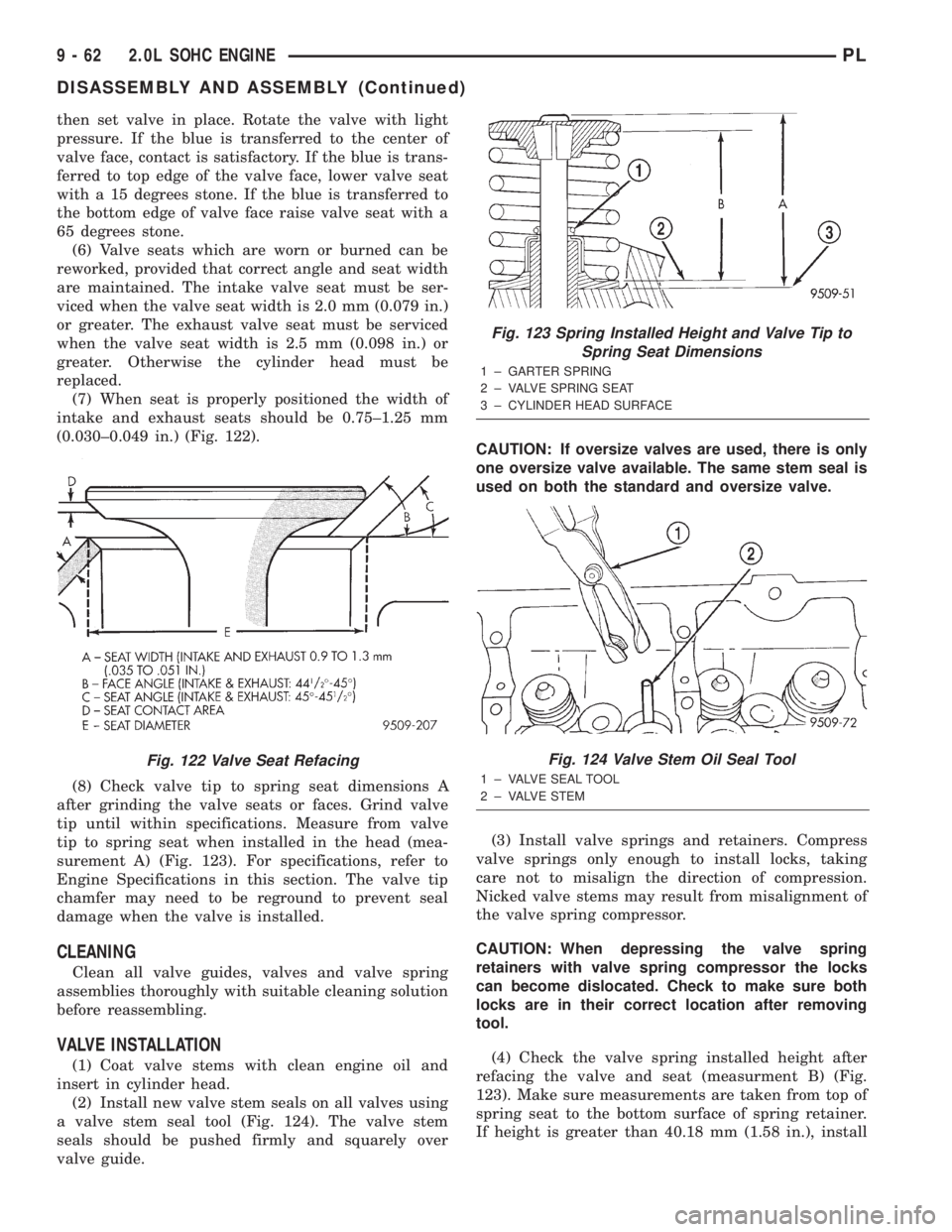
(7) When seat is properly positioned the width of
intake and exhaust seats should be 0.75±1.25 mm
(0.030±0.049 in.) (Fig. 122).
(8) Check valve tip to spring seat dimensions A
after grinding the valve seats or faces. Grind valve
tip until within specifications. Measure from valve
tip to spring seat when installed in the head (mea-
surement A) (Fig. 123). For specifications, refer to
Engine Specifications in this section. The valve tip
chamfer may need to be reground to prevent seal
damage when the valve is installed.
CLEANING
Clean all valve guides, valves and valve spring
assemblies thoroughly with suitable cleaning solution
before reassembling.
VALVE INSTALLATION
(1) Coat valve stems with clean engine oil and
insert in cylinder head.
(2) Install new valve stem seals on all valves using
a valve stem seal tool (Fig. 124). The valve stem
seals should be pushed firmly and squarely over
valve guide.CAUTION: If oversize valves are used, there is only
one oversize valve available. The same stem seal is
used on both the standard and oversize valve.
(3) Install valve springs and retainers. Compress
valve springs only enough to install locks, taking
care not to misalign the direction of compression.
Nicked valve stems may result from misalignment of
the valve spring compressor.
CAUTION: When depressing the valve spring
retainers with valve spring compressor the locks
can become dislocated. Check to make sure both
locks are in their correct location after removing
tool.
(4) Check the valve spring installed height after
refacing the valve and seat (measurment B) (Fig.
123). Make sure measurements are taken from top of
spring seat to the bottom surface of spring retainer.
If height is greater than 40.18 mm (1.58 in.), install
Fig. 122 Valve Seat Refacing
Fig. 123 Spring Installed Height and Valve Tip to
Spring Seat Dimensions
1 ± GARTER SPRING
2 ± VALVE SPRING SEAT
3 ± CYLINDER HEAD SURFACE
Fig. 124 Valve Stem Oil Seal Tool
1 ± VALVE SEAL TOOL
2 ± VALVE STEM
9 - 62 2.0L SOHC ENGINEPL
DISASSEMBLY AND ASSEMBLY (Continued)
Page 810 of 1285
FRAMES
TABLE OF CONTENTS
page page
DESCRIPTION AND OPERATION
FRONT SUSPENSION......................5
REMOVAL AND INSTALLATION
FRONT SUSPENSION CROSSMEMBER........5SPECIFICATIONS
FRAME DIMENSIONS......................9
STRUCTURAL DIMENSIONS................13
TORQUE SPECIFICATIONS.................15
DESCRIPTION AND OPERATION
FRONT SUSPENSION
The front suspension crossmember must be prop-
erly installed to achieve design camber, caster set-
tings and wheel stagger. The crossmember can be
installed out of position on the frame rails due to its
design. Bolts and cage nuts hold the rear of the
crossmember to the frame torque boxes. Bolts and
J-nuts hold the front of the crossmember to the
frame rails. No designed in locating device is used to
position the crossmember in the vehicle. Before
removing the crossmember mark the frame torque
box around the rear mounting location to aid instal-
lation. A crossmember that is removed during service
must be installed in the same position from which it
was removed. To verify that crossmember is in the
proper position, refer to the dimensions provided.
Front end dimensions are gauged from the principal
locating point (PLP) holes located under the frame
torque boxes rearward of the front wheels. After
removal and installation of the crossmember is per-
formed, verify that front suspension alignment is
within specifications. If camber, caster settings and
wheel stagger is not within specifications, loosen and
reposition crossmember to bring suspension within
specifications. Refer to Group 2, Front Suspension for
additional information.
REMOVAL AND INSTALLATION
FRONT SUSPENSION CROSSMEMBER
CAUTION: If the front suspension crossmember is
being replaced due to collision damage, inspect the
steering column lower coupling for damage. Refer
to STEERING COLUMN in the STEERING service
manual group for the procedure.
REMOVAL
(1) Raise the vehicle. Refer to HOISTING in the
LUBRICATION AND MAINTENANCE group in this
service manual for the correct lifting procedure.
(2) Remove both front tire and wheel assemblies
from the vehicle.
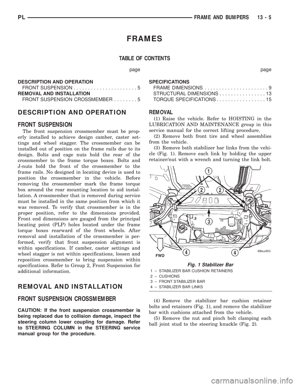
(3) Remove both stabilizer bar links from the vehi-
cle (Fig. 1). Remove each link by holding the upper
retainer/nut with a wrench and turning the link bolt.
(4) Remove the stabilizer bar cushion retainer
bolts and retainers (Fig. 1), and remove the stabilizer
bar with cushions attached from the vehicle.
(5) Remove the nut and pinch bolt clamping each
ball joint stud to the steering knuckle (Fig. 2).
Fig. 1 Stabilizer Bar
1 ± STABILIZER BAR CUSHION RETAINERS
2 ± CUSHIONS
3 ± FRONT STABILIZER BAR
4 ± STABILIZER BAR LINKS
PLFRAME AND BUMPERS 13 - 5
Page 814 of 1285
SPECIFICATIONS
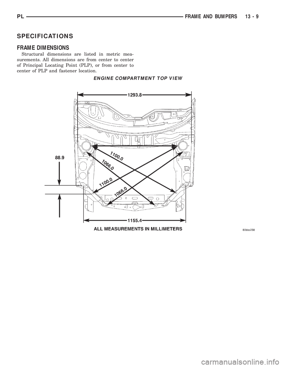
FRAME DIMENSIONS
Structural dimensions are listed in metric mea-
surements. All dimensions are from center to center
of Principal Locating Point (PLP), or from center to
center of PLP and fastener location.
ENGINE COMPARTMENT TOP VIEW
PLFRAME AND BUMPERS 13 - 9
Page 818 of 1285
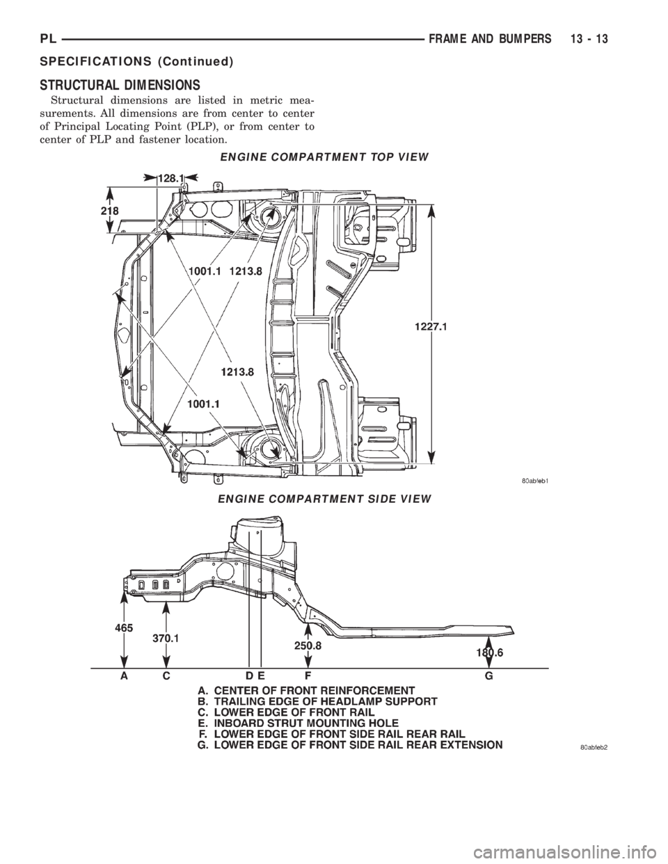
STRUCTURAL DIMENSIONS
Structural dimensions are listed in metric mea-
surements. All dimensions are from center to center
of Principal Locating Point (PLP), or from center to
center of PLP and fastener location.
ENGINE COMPARTMENT TOP VIEW
ENGINE COMPARTMENT SIDE VIEW
PLFRAME AND BUMPERS 13 - 13
SPECIFICATIONS (Continued)
Page 1048 of 1285
CLEANING AND INSPECTION
VALVE BODY
Allow all parts to soak a few minutes in a suitable
clean solvent. Wash thoroughly and blow dry with
compressed air. Be sure all passages are clean and
free from obstructions.
Inspect manual and throttle valve operating levers
and shafts for being bent, worn or loose. If a lever is
loose on its shaft, it should be replaced. Do not
attempt to straighten bent levers.
Inspect all mating surfaces for burrs, nicks and
scratches. Minor blemishes may be removed with cro-
cus cloth, using only a very light pressure. Using a
straightedge, inspect all mating surfaces for warpage
or distortion. Slight distortion may be corrected,
using a surface plate. Be sure all metering holes in
steel plate are open. Using a penlight, inspect bores
in valve body for scores, scratches, pits, and irregu-
larities.
Inspect all valve springs for distortion and col-
lapsed coils. Inspect all valves and plugs for burrs,
nicks, and scores. Small nicks and scores may be
removed with crocus cloth, providing extreme care is
taken not to round off sharp edges. The sharpness of
these edges is vitally important. It prevents foreign
matter from lodging between valve and valve body.
This reduces the possibility of sticking. Inspect all
valves and plugs for freedom of operation in valve
body bores.
When bores, valves, and plugs are clean and dry,
the valves and plugs should fall freely in the bores.
The valve body bores do not change their dimensions
with use. Therefore, a valve body that was function-
ing properly when vehicle was new, will operate cor-
rectly if it is properly and thoroughly cleaned. There
is no need to replace a valve body unless it is dam-
aged in handling.
ADJUSTMENTS
GEARSHIFT CABLE
Normal operation of the Park/Neutral Position
Switch provides a quick check to confirm proper link-
age adjustment. The engine starter should only oper-
ate when the transaxle shift lever is in the PARK (P)
or NEUTRAL (N) positions.
If the engine starts in any other gear position, or
the vehicle rolls when the shifter is in gated PARK
(P), a gearshift cable adjustment is necessary.
ADJUSTMENT
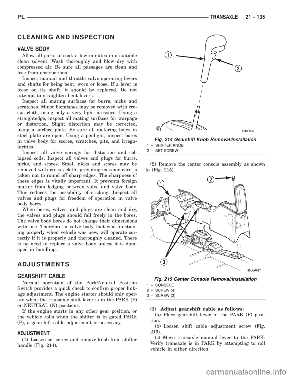
(1) Loosen set screw and remove knob from shifter
handle (Fig. 214).(2) Remove the center console assembly as shown
in (Fig. 215).
(3)Adjust gearshift cable as follows:
(a) Place gearshift lever in the PARK (P) posi-
tion.
(b) Loosen shift cable adjustment screw (Fig.
216).
(c) Move transaxle manual lever to the PARK.
Verify transaxle is in PARK by attempting to roll
vehicle in either direction.
Fig. 214 Gearshift Knob Removal/Installation
1 ± SHIFTER KNOB
2 ± SET SCREW
Fig. 215 Center Console Removal/Installation
1 ± CONSOLE
2 ± SCREW (4)
3 ± SCREW (2)
PLTRANSAXLE 21 - 135