2000 DODGE NEON radio
[x] Cancel search: radioPage 153 of 1285
DIAGNOSIS AND TESTING
SERVICE WARNINGS AND CAUTIONS
The ABS uses an electronic control module, the
CAB. This module is designed to withstand normal
current draws associated with vehicle operation.
Care must be taken to avoid overloading the CAB
circuits.
CAUTION: In testing for open or short circuits, do
not ground or apply voltage to any of the circuits
unless instructed to do so for a diagnostic proce-
dure.
CAUTION: These circuits should only be tested
using a high impedance multi-meter or the DRB
scan tool as described in this section. Power
should never be removed or applied to any control
module with the ignition in the ON position. Before
removing or connecting battery cables, fuses, or
connectors, always turn the ignition to the OFF
position.
CAUTION: Use only factory wiring harnesses. Do
not cut or splice wiring to the brake circuits. The
addition of after-market electrical equipment (car
phone, radar detector, citizen band radio, trailer
lighting, trailer brakes, etc.) on a vehicle equipped
with antilock brakes may affect the function of the
antilock brake system.
ABS GENERAL DIAGNOSTICS INFORMATION
This section contains information necessary to
diagnose the antilock brake system. Specifically, this
section should be used to help diagnose conditions
which result in any of the following:
(1) amber ABS warning lamp turned on.
(2) brakes lock-up on hard application.
Diagnosis of base brake conditions that are obvi-
ously mechanical in nature should be directed to
BASE BRAKE SYSTEM at the beginning of this
group.
Many ABS conditions judged to be a problem by
the driver may be normal operating conditions. See
ABS OPERATION in the DESCRIPTION AND
OPERATION section of this group to become famil-
iarized with the normal characteristics of this
antilock brake system.
ABS WIRING DIAGRAM INFORMATION
During the diagnosis and testing of the antilock
brake system it may become necessary to reference
the wiring diagrams covering the antilock brake sys-
tem and its components. For wiring diagrams refer to
GROUP 8W of this service manual. It will provide
you with the wiring diagrams and the circuit descrip-
tion and operation information covering the antilock
brake system.
ABS VEHICLE TEST DRIVE
Most ABS complaints will require a test drive to
properly duplicate and diagnose the condition.
WARNING: CONDITIONS THAT RESULT IN TURN-
ING ON THE RED BRAKE WARNING LAMP MAY
INDICATE REDUCED BRAKING ABILITY.
Before test driving a brake complaint vehicle, note
whether the red BRAKE warning lamp, amber ABS
warning lamp, or both are turned on. If it is the red
BRAKE warning lamp, there is a brake hydraulic
problem that must be corrected before driving the
vehicle. Refer to the BASE BRAKE SYSTEM for
diagnosis of the red BRAKE warning lamp. If the red
brake warning lamp is illuminated, there is also a
possibility that there is an ABS problem and the
amber ABS warning lamp is not able to illuminate,
so the MIC turns on the red Brake warning lamp by
default.
If the amber ABS warning lamp is on, test drive
the vehicle as described below. While the amber ABS
warning lamp is on, the ABS is not functional. The
ability to stop the car using the base brake system
should not be affected.
If a functional problem of the ABS is determined
while test driving the vehicle, refer to the Chassis
Diagnostic Procedures manual.
(1) Turn the key to the OFF position and then
back to the ON position. Note whether the amber
ABS warning lamp continues to stay on. If it does,
refer to the diagnostic manual.
(2) If the amber ABS warning lamp goes out, shift
into gear and drive the car to a speed of 20 kph (12
mph) to complete the ABS start-up and drive-off
cycles (see ABS ELECTRONIC DIAGNOSIS). If at
this time the amber ABS warning lamp comes on,
refer to the diagnostic manual.
(3) If the amber ABS warning lamp remains out,
drive the vehicle a short distance. Accelerate the
vehicle to a speed of at least 40 mph. Bring the vehi-
cle to a complete stop, braking hard enough to cause
the ABS to cycle. Again accelerate the vehicle past 25
mph. Refer to the diagnostic manual for further test-
ing of the antilock brake system.
5 - 74 BRAKESPL
Page 215 of 1285
Refer to Group 8W, Wiring Diagrams. If OK go to
Step 7.
(7) Install interior lamp fuse. After installing fuse,
the current can reach 250 milliamperes. After time-
out the reading should not exceed 8 milliamperes. If
NOT OK go to Step 8. If OK go to Step 9.
²Ignition key lamp system
²Radio
²Remote keyless entry module, if equipped
(8) Disconnect radio and ignition switch key lamp
one component at time, to see if any component is at
fault. If the high reading is not eliminated there is a
short circuit in the wiring. Refer to Group 8W, Wir-
ing Diagrams.
CAUTION: Always disconnect the meter before
opening a door.
(9) Remove interior lamps fuse and install the fuel
pump fuse. The reading should be between 1-3 milli-
amperes. If reading is higher than 3 milliamperes:
(a) Disconnect Powertrain Control Module.
(b) If reading drops to zero, replace Powertrain
Control Module.
(c) If reading remains the same there is a cur-
rent draw or short circuit in the A14 circuit. Refer
to Group 8W, Wiring Diagrams.
BATTERY LOAD TEST
A fully charged battery must have cranking capac-
ity, to provide the starter motor and ignition system
enough power to start the engine over a broad range
of ambient temperatures. A battery load test will ver-
ify the actual cranking capability of the battery.WARNING: IF BATTERY SHOWS SIGNS OF FREEZ-
ING, LEAKING, LOOSE POSTS, OR EXCESSIVELY
LOW ELECTROLYTE LEVEL, DO NOT TEST. ACID
BURNS OR AN EXPLOSIVE CONDITION MAY
RESULT.
(1) Remove both battery cables, negative cable
first. The battery top, cables and posts should be
clean. If green dot is not visible in indicator, charge
the battery. Refer to Battery Charging Procedures in
this group.
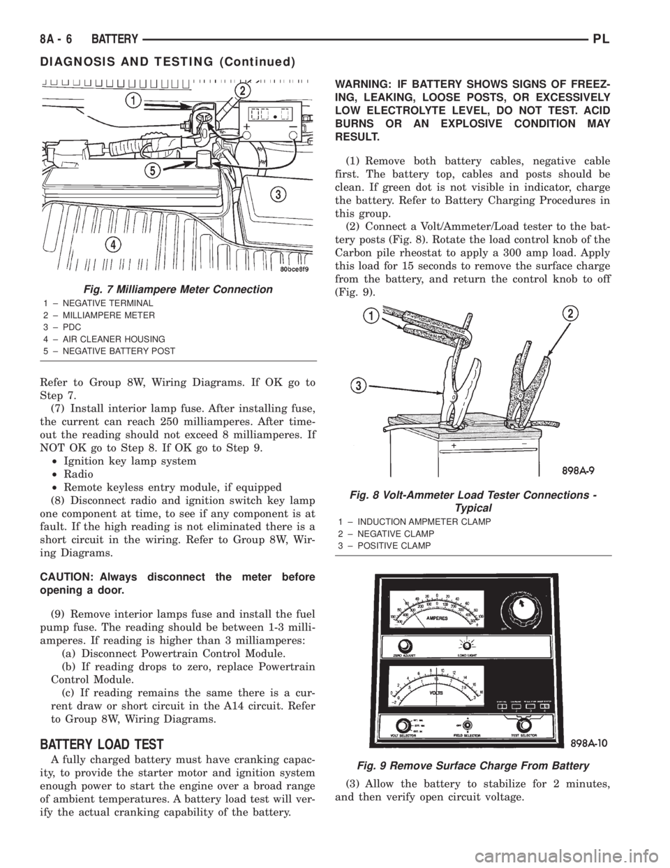
(2) Connect a Volt/Ammeter/Load tester to the bat-
tery posts (Fig. 8). Rotate the load control knob of the
Carbon pile rheostat to apply a 300 amp load. Apply
this load for 15 seconds to remove the surface charge
from the battery, and return the control knob to off
(Fig. 9).
(3) Allow the battery to stabilize for 2 minutes,
and then verify open circuit voltage.
Fig. 7 Milliampere Meter Connection
1 ± NEGATIVE TERMINAL
2 ± MILLIAMPERE METER
3 ± PDC
4 ± AIR CLEANER HOUSING
5 ± NEGATIVE BATTERY POST
Fig. 8 Volt-Ammeter Load Tester Connections -
Typical
1 ± INDUCTION AMPMETER CLAMP
2 ± NEGATIVE CLAMP
3 ± POSITIVE CLAMP
Fig. 9 Remove Surface Charge From Battery
8A - 6 BATTERYPL
DIAGNOSIS AND TESTING (Continued)
Page 236 of 1285
IGNITION SYSTEM
TABLE OF CONTENTS
page page
DESCRIPTION AND OPERATION
IGNITION SYSTEM........................1
SPARK PLUGS...........................1
SPARK PLUG CABLES.....................1
ELECTRONIC IGNITION COILS...............2
AUTOMATIC SHUTDOWN RELAY.............2
CRANKSHAFT POSITION SENSORÐPCM
INPUT................................3
CAMSHAFT POSITION SENSORÐPCM
INPUT................................4
KNOCK SENSOR..........................5
IGNITION SWITCH........................5
LOCK KEY CYLINDER......................5
IGNITION INTERLOCK.....................6
REMOVAL AND INSTALLATION
SPARK PLUG SERVICE....................6SPARK PLUG CABLE SERVICE..............6
IGNITION COIL...........................6
AUTOMATIC SHUTDOWN RELAY.............6
CAMSHAFT POSITION SENSOR..............6
CRANKSHAFT POSITION SENSOR............8
KNOCK SENSOR..........................8
IGNITION SWITCH........................8
LOCK KEY CYLINDER......................9
IGNITION INTERLOCK....................10
SPECIFICATIONS
VECI LABEL............................10
FIRING ORDERÐ2.0L....................10
TORQUE SPECIFICATION..................11
SPARK PLUG CABLE RESISTANCEÐSOHC....11
SPARK PLUG...........................11
IGNITION COIL..........................11
DESCRIPTION AND OPERATION
IGNITION SYSTEM
DESCRIPTION
The system's three main components are the coil
pack, crankshaft position sensor, and camshaft posi-
tion sensor.
OPERATION
Basic ignition timing is not adjustable.The
Powertrain Control Module (PCM) determines spark
advance. The 2.0L engines use a fixed ignition timing
system. The distributorless electronic ignition system
is referred to as the Direct Ignition System (DIS).
SPARK PLUGS
The 2.0L engines uses resistor spark plugs. For
spark plug identification and specifications, Refer to
the Specifications section at the end of this group.
Remove the spark plugs and examine them for
burned electrodes and fouled, cracked or broken por-
celain insulators. Keep plugs arranged in the order
in which they were removed from the engine. An iso-
lated plug displaying an abnormal condition indicates
that a problem exists in the corresponding cylinder.
Spark plugs that have low mileage may be cleaned
and reused if not otherwise defective. Refer to the
Spark Plug Condition section of this group. Aftercleaning, file the center electrode flat with a small
point file or jewelers file. Adjust the gap between the
electrodes (Fig. 1) to the dimensions specified in the
chart at the end of this section by bending the
ground electrode (just above the attachment weld)
with the appropriate tool.
Never apply any force between the electrode or
damage to the center electrode assembly will result.
Always tighten spark plugs to the specified torque.
Over tightening can cause distortion and damage.
Tighten spark plugs to 28 N´m (20 ft. lbs.) torque.
SPARK PLUG CABLES
Spark plug cables are sometimes referred to as sec-
ondary ignition wires. The wires transfer electrical
current from the coil pack to individual spark plugs
at each cylinder. The resistor type, nonmetallic spark
plug cables provide suppression of radio frequency
emissions from the ignition system.
Check the spark plug cable connections for good
contact at the coil and spark plugs. Terminals should
be fully seated. The nipples and spark plug covers
should be in good condition. Nipples should fit tightly
on the coil. Spark plug boot should completely cover
the spark plug hole in the cylinder head cover. Install
the boot until the terminal snaps over the spark
plug. A snap must be felt to ensure the spark plug
cable terminal engaged the spark plug.
PLIGNITION SYSTEM 8D - 1
Page 241 of 1285
IGNITION INTERLOCK
OPERATION
All vehicles equipped with automatic transaxles
have an interlock system. The system prevents shift-
ing the vehicle out of Park unless the ignition lock
cylinder is in the Off, Run or Start position. In addi-
tion, the operator cannot rotate the key to the lock
position unless the shifter is in the park position. On
vehicles equipped with floor shift refer to the - Tran-
saxle for Automatic Transmission Shifter/Ignition
Interlock.
REMOVAL AND INSTALLATION
SPARK PLUG SERVICE
Failure to route the cables properly could cause the
radio to reproduce ignition noise, cross ignition of the
spark plugs or short circuit the cables to ground.
REMOVAL
REMOVE CABLES FROM COIL FIRST.
Always remove the spark plug cable by grasping
the top of the spark plug insulator, turning the boot
1/2 turn and pulling straight up in a steady motion.
(1) Remove the spark plug using a quality socket
with a rubber or foam insert.
(2) Inspect the spark plug condition.
INSTALLATION
(1) To avoid cross threading, start the spark plug
into the cylinder head by hand.
(2) Tighten spark plugs to 28 N´m (20 ft. lbs.)
torque.
(3) Install spark plug insulators over spark plugs.
Ensure the top of the spark plug insulator covers the
upper end of the spark plug tube.
Reconnect to coil.
SPARK PLUG CABLE SERVICE
Failure to route the cables properly could cause the
radio to reproduce ignition noise, cross ignition of the
spark plugs or short circuit the cables to ground.
REMOVAL
Remove spark plug cable from coil first.
Always remove the spark plug cable by grasping
the top of the spark plug insulator, turning the boot
1/2 turn and pulling straight up in a steady motion.
INSTALLATION
Install spark plug insulators over spark plugs.
Ensure the top of the spark plug insulator covers the
upper end of the spark plug tube. The connect theother end to coil pack. Be sure that dual plastic clip
holds the cables off of the valve cover.
IGNITION COIL
The electronic ignition coil pack attaches directly
to the valve cover (Fig. 11).
REMOVAL
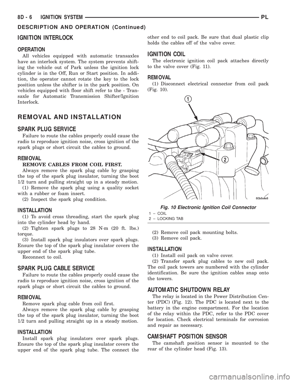
(1) Disconnect electrical connector from coil pack
(Fig. 10).
(2) Remove coil pack mounting bolts.
(3) Remove coil pack.
INSTALLATION
(1) Install coil pack on valve cover.
(2) Transfer spark plug cables to new coil pack.
The coil pack towers are numbered with the cylinder
identification. Be sure the ignition cables snap onto
the towers.
AUTOMATIC SHUTDOWN RELAY
The relay is located in the Power Distribution Cen-
ter (PDC) (Fig. 12). The PDC is located next to the
battery in the engine compartment. For the location
of the relay within the PDC, refer to the PDC cover
for location. Check electrical terminals for corrosion
and repair as necessary.
CAMSHAFT POSITION SENSOR
The camshaft position sensor is mounted to the
rear of the cylinder head (Fig. 13).
Fig. 10 Electronic Ignition Coil Connector
1 ± COIL
2 ± LOCKING TAB
8D - 6 IGNITION SYSTEMPL
DESCRIPTION AND OPERATION (Continued)
Page 248 of 1285
INSTRUMENT PANEL SYSTEMS
TABLE OF CONTENTS
page page
GENERAL INFORMATION
INTRODUCTION..........................1
DESCRIPTION AND OPERATION
HEADLAMP SWITCH......................2
INSTRUMENT CLUSTER....................2
WARNING AND INDICATOR LAMPS..........2
DIAGNOSIS AND TESTING
AIRBAG WARNING SYSTEM................2
BRAKE SYSTEM WARNING LAMP TEST.......2
INSTRUMENT CLUSTER LAMPS.............2
LOW OIL PRESSURE WARNING LAMP TEST...3
MULTIPLE/INDIVIDUAL GAUGES
INOPERATIVE..........................4
SERVICE PROCEDURES
INSTRUMENT CLUSTER SELF-DIAGNOSTICS...4
REMOVAL AND INSTALLATION
ACCESSORY SWITCH/POWER OUTLET
BEZEL................................4CENTER CONSOLE FLOOD LAMP............5
CIGAR LIGHTER / POWER OUTLET
ASSEMBLY.............................5
GLOVE BOX DOOR/BIN....................6
GLOVE BOX DOOR/BIN....................6
GLOVE BOX SWITCH/LAMP.................6
INSTRUMENT CLUSTER....................6
INSTRUMENT CLUSTER BEZEL..............6
INSTRUMENT CLUSTER LAMPS.............7
INSTRUMENT PANEL ASSEMBLY............7
INSTRUMENT PANEL CENTER BEZEL........10
INSTRUMENT PANEL END CAPS............10
INSTRUMENT PANEL TOP COVER...........10
LOWER INSTRUMENT PANEL COVER........10
LOWER STORAGE BIN....................10
STEERING COLUMN SHROUDS.............11
GENERAL INFORMATION
INTRODUCTION
The purpose of the dash gauges and indicator
lamps is to keep the driver informed about the oper-
ating condition of the vehicle. If an abnormal condi-
tion occurs, the driver is informed by indicator lamp.
The driver can seek service before damage occurs.
Indicator lamps use ON/OFF switch functions for
operation, while gauges use a sending unit or sensor.
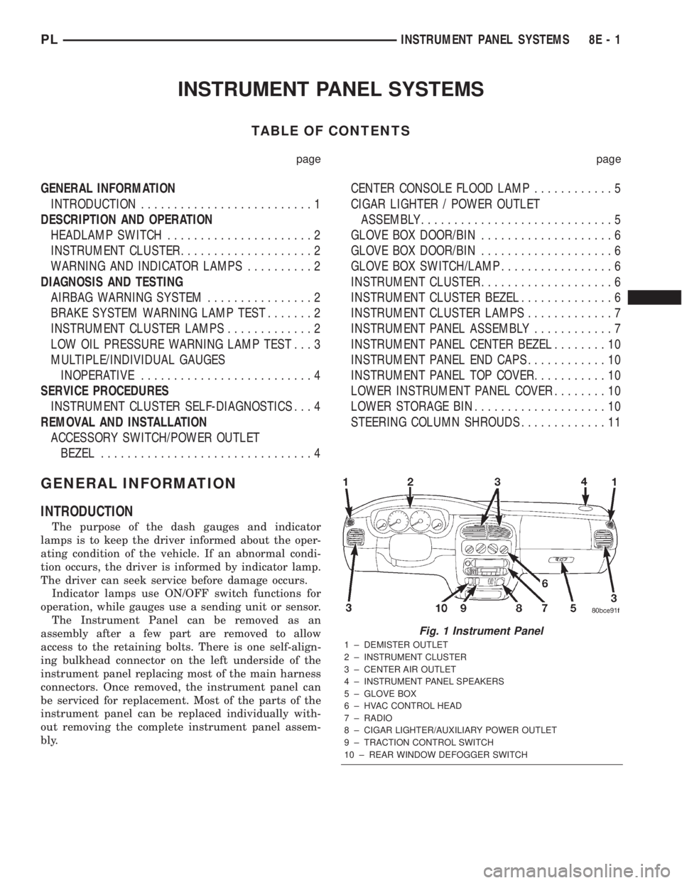
The Instrument Panel can be removed as an
assembly after a few part are removed to allow
access to the retaining bolts. There is one self-align-
ing bulkhead connector on the left underside of the
instrument panel replacing most of the main harness
connectors. Once removed, the instrument panel can
be serviced for replacement. Most of the parts of the
instrument panel can be replaced individually with-
out removing the complete instrument panel assem-
bly.
Fig. 1 Instrument Panel
1 ± DEMISTER OUTLET
2 ± INSTRUMENT CLUSTER
3 ± CENTER AIR OUTLET
4 ± INSTRUMENT PANEL SPEAKERS
5 ± GLOVE BOX
6 ± HVAC CONTROL HEAD
7 ± RADIO
8 ± CIGAR LIGHTER/AUXILIARY POWER OUTLET
9 ± TRACTION CONTROL SWITCH
10 ± REAR WINDOW DEFOGGER SWITCH
PLINSTRUMENT PANEL SYSTEMS 8E - 1
Page 255 of 1285
(19) Disconnect one left side harness connector at
top left of instrument panel for vanity and rear view
mirrors.
(20) Pull off the hvac control head knobs.
(21) Remove two screws retaining the top front of
the center bezel.
(22) Using a trim stick, gently pry out on the
instrument panel center bezel and remove.
(23) Remove the two retaining screws to the hvac
control head.
(24) Disconnect the one instrument panel wire
harness connector.
(25) Disconnect the one vacuum harness connector.
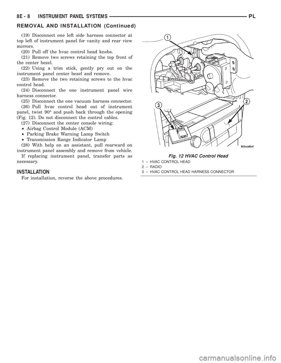
(26) Pull hvac control head out of instrument
panel, twist 90É and push back through the opening
(Fig. 12). Do not disconnect the control cables.
(27) Disconnect the center console wiring:
²Airbag Control Module (ACM)
²Parking Brake Warning Lamp Switch
²Transmission Range Indicator Lamp
(28) With help on an assistant, pull rearward on
instrument panel assembly and remove from vehicle.
If replacing instrument panel, transfer parts as
necessary.
INSTALLATION
For installation, reverse the above procedures.
Fig. 12 HVAC Control Head
1 ± HVAC CONTROL HEAD
2 ± RADIO
3 ± HVAC CONTROL HEAD HARNESS CONNECTOR
8E - 8 INSTRUMENT PANEL SYSTEMSPL
REMOVAL AND INSTALLATION (Continued)
Page 264 of 1285
(15) Rotate the A/C outlet registers to the full
down position. Grip each outlet at its outboard end
and gently over-rotate to release from its pivot point.
Swing outlet straight out and remove by hand
(16) Remove the (4) HVAC control knobs by pull-
ing them straight off the switch shaft by hand.
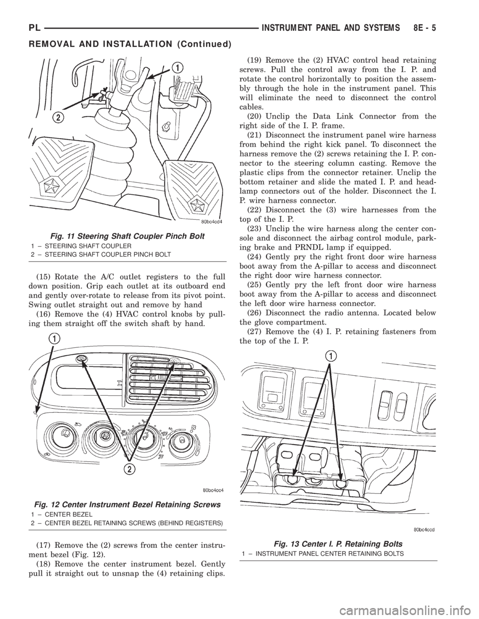
(17) Remove the (2) screws from the center instru-
ment bezel (Fig. 12).
(18) Remove the center instrument bezel. Gently
pull it straight out to unsnap the (4) retaining clips.(19) Remove the (2) HVAC control head retaining
screws. Pull the control away from the I. P. and
rotate the control horizontally to position the assem-
bly through the hole in the instrument panel. This
will eliminate the need to disconnect the control
cables.
(20) Unclip the Data Link Connector from the
right side of the I. P. frame.
(21) Disconnect the instrument panel wire harness
from behind the right kick panel. To disconnect the
harness remove the (2) screws retaining the I. P. con-
nector to the steering column casting. Remove the
plastic clips from the connector retainer. Unclip the
bottom retainer and slide the mated I. P. and head-
lamp connectors out of the holder. Disconnect the I.
P. wire harness connector.
(22) Disconnect the (3) wire harnesses from the
top of the I. P.
(23) Unclip the wire harness along the center con-
sole and disconnect the airbag control module, park-
ing brake and PRNDL lamp if equipped.
(24) Gently pry the right front door wire harness
boot away from the A-pillar to access and disconnect
the right door wire harness connector.
(25) Gently pry the left front door wire harness
boot away from the A-pillar to access and disconnect
the left door wire harness connector.
(26) Disconnect the radio antenna. Located below
the glove compartment.
(27) Remove the (4) I. P. retaining fasteners from
the top of the I. P.
Fig. 11 Steering Shaft Coupler Pinch Bolt
1 ± STEERING SHAFT COUPLER
2 ± STEERING SHAFT COUPLER PINCH BOLT
Fig. 12 Center Instrument Bezel Retaining Screws
1 ± CENTER BEZEL
2±
CENTER BEZEL RETAINING SCREWS (BEHIND REGISTERS)
Fig. 13 Center I. P. Retaining Bolts
1 ± INSTRUMENT PANEL CENTER RETAINING BOLTS
PLINSTRUMENT PANEL AND SYSTEMS 8E - 5
REMOVAL AND INSTALLATION (Continued)
Page 265 of 1285
(28) Remove the (2) I. P. retaining bolts which
attach the I. P. to the body at the tunnel bracket
(Fig. 13).
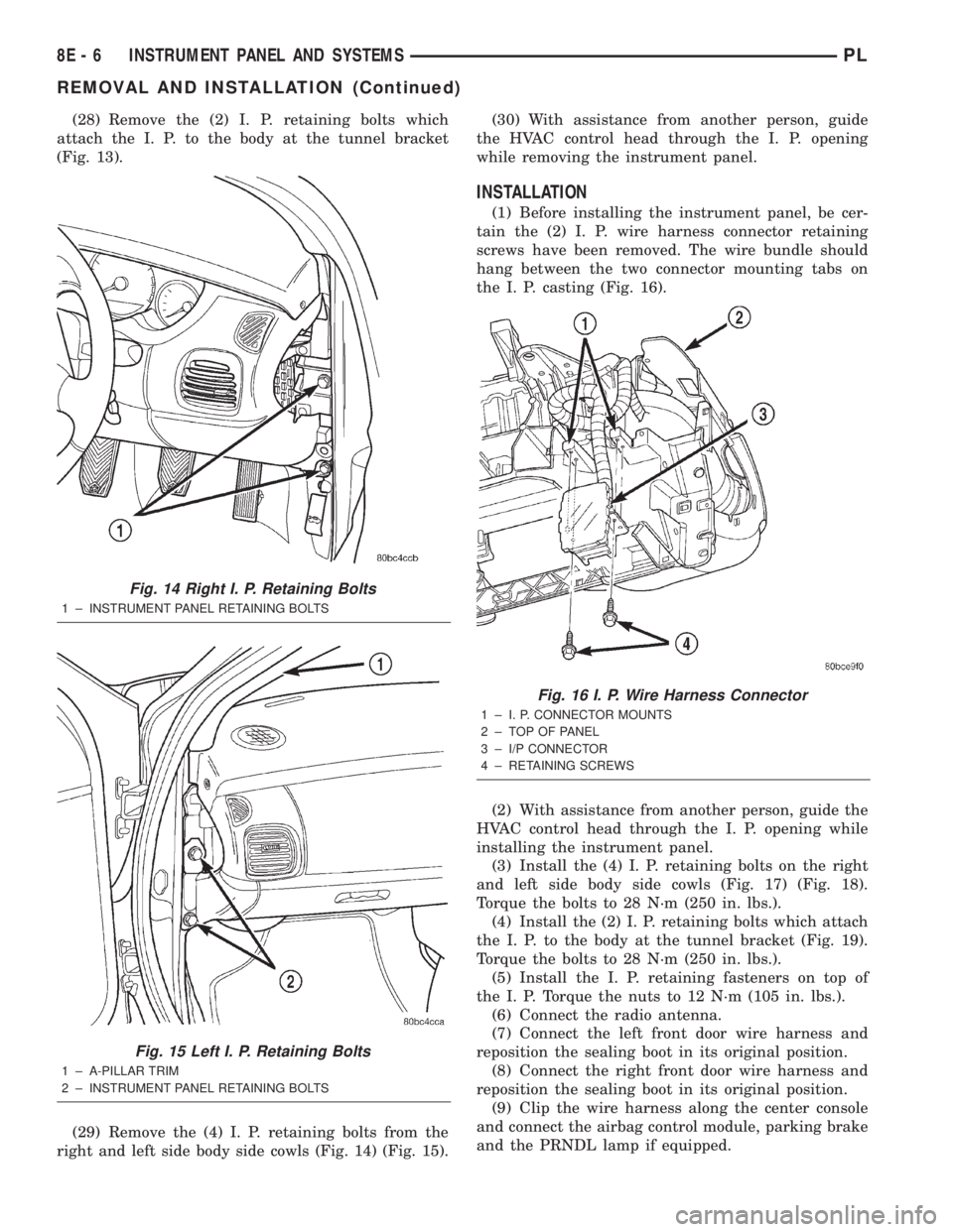
(29) Remove the (4) I. P. retaining bolts from the
right and left side body side cowls (Fig. 14) (Fig. 15).(30) With assistance from another person, guide
the HVAC control head through the I. P. opening
while removing the instrument panel.
INSTALLATION
(1) Before installing the instrument panel, be cer-
tain the (2) I. P. wire harness connector retaining
screws have been removed. The wire bundle should
hang between the two connector mounting tabs on
the I. P. casting (Fig. 16).
(2) With assistance from another person, guide the
HVAC control head through the I. P. opening while
installing the instrument panel.
(3) Install the (4) I. P. retaining bolts on the right
and left side body side cowls (Fig. 17) (Fig. 18).
Torque the bolts to 28 N´m (250 in. lbs.).
(4) Install the (2) I. P. retaining bolts which attach
the I. P. to the body at the tunnel bracket (Fig. 19).
Torque the bolts to 28 N´m (250 in. lbs.).
(5) Install the I. P. retaining fasteners on top of
the I. P. Torque the nuts to 12 N´m (105 in. lbs.).
(6) Connect the radio antenna.
(7) Connect the left front door wire harness and
reposition the sealing boot in its original position.
(8) Connect the right front door wire harness and
reposition the sealing boot in its original position.
(9) Clip the wire harness along the center console
and connect the airbag control module, parking brake
and the PRNDL lamp if equipped.
Fig. 14 Right I. P. Retaining Bolts
1 ± INSTRUMENT PANEL RETAINING BOLTS
Fig. 15 Left I. P. Retaining Bolts
1 ± A-PILLAR TRIM
2 ± INSTRUMENT PANEL RETAINING BOLTS
Fig. 16 I. P. Wire Harness Connector
1 ± I. P. CONNECTOR MOUNTS
2 ± TOP OF PANEL
3 ± I/P CONNECTOR
4 ± RETAINING SCREWS
8E - 6 INSTRUMENT PANEL AND SYSTEMSPL
REMOVAL AND INSTALLATION (Continued)