2000 DODGE NEON radio
[x] Cancel search: radioPage 270 of 1285
AUDIO SYSTEM
TABLE OF CONTENTS
page page
GENERAL INFORMATION
INTRODUCTION..........................1
DESCRIPTION AND OPERATION
INTERFERENCE ELIMINATION...............1
DIAGNOSIS AND TESTING
AUDIO DIAGNOSTIC TEST PROCEDURES......1
TESTING................................1
BENCH TEST FOR ANTENNA MALFUNCTION...7REMOVAL AND INSTALLATION
CD CHANGER............................7
FRONT DOOR SPEAKER....................8
INSTRUMENT PANEL SPEAKER(S)...........8
MAST and ANTENNA ASSEMBLY.............8
RADIO..................................9
REAR SHELF SPEAKER(S).................10
GENERAL INFORMATION
INTRODUCTION
Operating instructions for the factory installed
audio systems can be found in the Owner's Manual
provided with the vehicle.
The vehicles are equipped with an Interior (Igni-
tion Off Draw) fuse in the Power Distribution Center
located in the engine compartment. After the Interior
(IOD) fuse or battery has been disconnected the clock
will require resetting. The radio station presets have
a nonvolatile memory and will retain the preset sta-
tions after a battery disconnect.
The available radio options are:
²AM/FM Stereo Cassette w/Clock
²AM/FM/CD
²AM/FM Cassette w/CD Changer Controls and
Display
²CD/4 Disc Changer - In-Dash (used w/Radio CD
Changer Controls)
DESCRIPTION AND OPERATION
INTERFERENCE ELIMINATION
The radio utilizes a ground wire plugged on to a
blade terminal and is bolted to the radio chassis.
Both connector and terminal should be securely
attached. The engine has two separate ground straps
to suppress ignition noise which may interfere with
radio reception.
²Left engine mount clip on strap
²Engine to shock tower reinforcement
Inductive type spark plug cables in the high ten-
sion circuit of the ignition system complete the inter-
ference suppression. Faulty or deteriorated spark
plug wires should be replaced.
DIAGNOSIS AND TESTING
AUDIO DIAGNOSTIC TEST PROCEDURES
CAUTION: The CD player will only operate between
approximate temperatures of -23ÉC and +65ÉC (-10ÉF
and +145ÉF).
Whenever a radio malfunction occurs;
(1) First check FUSES:
(a) Power Distribution Center (PDC), Interior
lamp fuse, M1 - Radio Memory Feed
(b) Fuse Block:
(I) Fuse 12, Illumination in the fuse block
(II) Fuse 16, Ignition feed in the fuse block
NOTE: The vehicles are shipped with the INTERIOR
LAMP fuse disconnected.
(2) Verify, the radio wire harness are properly con-
nected before starting normal diagnosis and repair
procedures. Refer to Audio Diagnostic Charts and/or
Group 8W, Wiring Diagrams, Radio Section.
TESTING
The antenna has a short cable which connects into
the instrument panel harness. The connection is
made on the right side of the instrument panel.
Antenna performance may be tested by substitut-
ing a known good antenna. It is also possible to
check short or open circuits with an ohmmeter or
continuity light once the antenna cable is discon-
nected from the radio as follows:
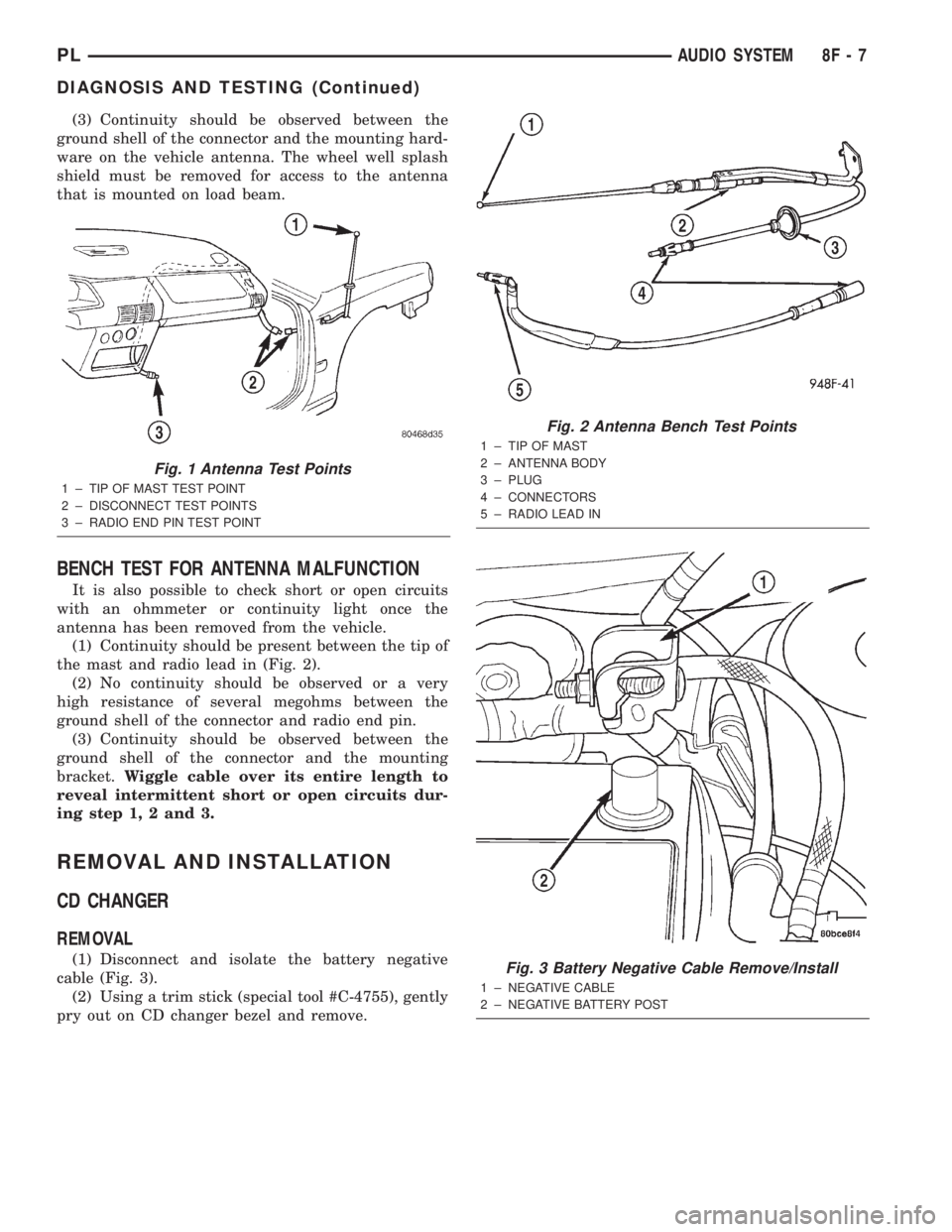
(1) Continuity should be present between the
antenna mast and radio end pin of antenna cable
plug (Fig. 1).
(2) No continuity should be observed or a very
high resistance of several megohms between the
ground shell of the connector and radio end pin.
PLAUDIO SYSTEM 8F - 1
Page 276 of 1285
(3) Continuity should be observed between the
ground shell of the connector and the mounting hard-
ware on the vehicle antenna. The wheel well splash
shield must be removed for access to the antenna
that is mounted on load beam.
BENCH TEST FOR ANTENNA MALFUNCTION
It is also possible to check short or open circuits
with an ohmmeter or continuity light once the
antenna has been removed from the vehicle.
(1) Continuity should be present between the tip of
the mast and radio lead in (Fig. 2).
(2) No continuity should be observed or a very
high resistance of several megohms between the
ground shell of the connector and radio end pin.
(3) Continuity should be observed between the
ground shell of the connector and the mounting
bracket.Wiggle cable over its entire length to
reveal intermittent short or open circuits dur-
ing step 1, 2 and 3.
REMOVAL AND INSTALLATION
CD CHANGER
REMOVAL
(1) Disconnect and isolate the battery negative
cable (Fig. 3).
(2) Using a trim stick (special tool #C-4755), gently
pry out on CD changer bezel and remove.
Fig. 1 Antenna Test Points
1 ± TIP OF MAST TEST POINT
2 ± DISCONNECT TEST POINTS
3 ± RADIO END PIN TEST POINT
Fig. 2 Antenna Bench Test Points
1 ± TIP OF MAST
2 ± ANTENNA BODY
3 ± PLUG
4 ± CONNECTORS
5 ± RADIO LEAD IN
Fig. 3 Battery Negative Cable Remove/Install
1 ± NEGATIVE CABLE
2 ± NEGATIVE BATTERY POST
PLAUDIO SYSTEM 8F - 7
DIAGNOSIS AND TESTING (Continued)
Page 278 of 1285
INSTALLATION
(1) Align antenna adapter tongue with grove in
the fender hole and push adapter into fender.
(2) From under the fender, push the antenna base
and cable assembly through the adapter in the
fender. Tighten mounting screws to 7 N´m (75 in.
lbs.).
(3) Seat the grommet in the side panel and con-
nect the cable to the instrument panel harness con-
nector.
(4) Install the plastic inner fender shield.
(5) Connect the antenna cable to the instrument
panel cable lead.
(6) Install right cowl side trim panel.
RADIO
REMOVAL
(1) Disconnect and isolate the battery negative
cable (Fig. 3).
(2) Remove instrument panel center bezel. Refer to
Group 8E Instrument Panel Systems, Instrument
Panel Top Cover Removal and Installation.
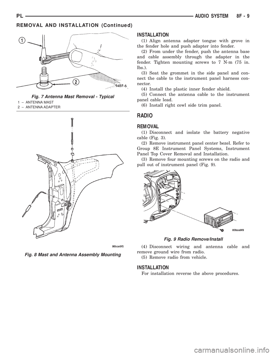
(3) Remove four mounting screws on the radio and
pull out of instrument panel (Fig. 9).
(4) Disconnect wiring and antenna cable and
remove ground wire from radio.
(5) Remove radio from vehicle.
INSTALLATION
For installation reverse the above procedures.
Fig. 7 Antenna Mast Removal - Typical
1 ± ANTENNA MAST
2 ± ANTENNA ADAPTER
Fig. 8 Mast and Antenna Assembly Mounting
Fig. 9 Radio Remove/Install
PLAUDIO SYSTEM 8F - 9
REMOVAL AND INSTALLATION (Continued)
Page 367 of 1285

REMOTE KEYLESS ENTRY (RKE)
TABLE OF CONTENTS
page page
DESCRIPTION AND OPERATION
INTRODUCTION..........................4
REMOTE KEYLESS ENTRY SYSTEM..........5
REMOTE KEYLESS ENTRY TRANSMITTER.....5
HORN CHIRP TOGGLE.....................5
DIAGNOSIS AND TESTING
REMOTE KEYLESS ENTRY MODULE..........5
DECKLID RELEASE SOLENOID...............5
SERVICE PROCEDURES
HORN CHIRP TOGGLE.....................5SWITCHING OPERATING MODES/
CONFIGURING A NEW MODULE............6
TRANSMITTER PROGRAMMING..............6
REMOVAL AND INSTALLATION
DECK LID RELEASE SOLENOID..............6
REMOTE KEYLESS ENTRY MODULE..........6
SPECIFICATIONS
TRANSMITTER BATTERY...................7
TRANSMITTER RANGE.....................7
DESCRIPTION AND OPERATION
INTRODUCTION
The system allows locking and unlocking of vehicle
door(s), deck lid release, and panic by remote control
using a hand held radio frequency transmitter (Fig.
1). The module must be in the customer usage mode
of operation for the remote keyless entry system to
function.
The receiver may receive signals from up to four
transmitters. Each transmitter has its own code, and
the code is programmed and stored into RKE module
memory. If a transmitter is replaced or additional
transmitters are added, the codes for all units have
to be reprogrammed into the RKE module memory. If
a receiver module is replaced, the transmitter codes
must be stored in the new receiver memory (by per-
forming the steps for programming transmitters).The RKE module is capable of retaining all transmit-
ter codes when power is removed from the module.
Operation of the Remote Keyless Entry system
works in a similar manner to the central locking/un-
locking feature. With the double activation unlock
feature enabled, the first press of the transmitter
UNLOCK button will electrically unlock the driver
door, and a second press of the UNLOCK button
(within five seconds of the first) will unlock all vehi-
cle doors. With the double activation feature dis-
abled, all vehicle doors will unlock upon the first
press of the transmitter UNLOCK button. The vehi-
cle is locked electrically by pressing the transmitter
LOCK button once, regardless of the state of the dou-
ble activation unlock feature. The vehicle is shipped
with the double activation unlock feature enabled.
The deck lid can be unlatched manually via the
key cylinder from outside the vehicle, or by depress-
ing the deck lid release button on the RKE transmit-
ter twice (within five seconds).
The RKE module has three modes of operation
including customer usage mode, dealer lot storage
mode, and shipping mode. The customer usage mode
provides full functionality of the module and is the
mode in which the RKE module should be operating
when used by the customer. Dealer lot storage mode
and shipping modes are reduced power modes meant
to extend vehicle battery life during shipping and
storage in the dealer lot. Dealer lot storage mode pro-
vides limited VTSS and power door lock functions,
but disables the Remote Keyless Entry (RKE) func-
tions. This mode is intended to be used when the
vehicle is on the dealer lot to provide VTSS coverage
of the vehicle while minimizing battery drain. Ship-
ping mode disables all normal functions (i.e. power
door locks, RKE, and VTSS) of the module, and is
intended to be used when the vehicle is shipped from
the assembly plant.
Fig. 1 Remote Keyless Entry (Key Fob) Transmitter
1 ± BATTERIES
8P - 4 POWER LOCK SYSTEMSPL
Page 368 of 1285
NOTE: The dealer must remove the module from
ªShip Modeº and place the RKE Module into either
the ªDealer Lotº storage or ªCustomer Usageº
modes of operation after receiving the vehicle from
the assembly plant. Refer to Group 8Q-Vehicle
Theft/Security Systems, Switching Operating
Modes/Configuring a New Module under Service
Procedures.
REMOTE KEYLESS ENTRY SYSTEM
The system allows locking and unlock of vehicle
door(s) and deck lid by remote control using a hand
held radio frequency (RF) transmitter. The vehicle
speed must be less than five miles per hour before
the deck lid can be unlatched with the transmitter.
The receiver may receive signals from four transmit-
ters. Each transmitter has its own code and the code
has been stored in memory. If the transmitter is
replaced or other transmitters are added, the code for
each unit must be learned.
REMOTE KEYLESS ENTRY TRANSMITTER
The transmitter has four buttons for operation
(Fig. 1). They are LOCK, UNLOCK, DECK LID
RELEASE, and PANIC.
²The UNLOCK button will unlock the driver door
and enable illuminated entry. Pushing and releasing
the button once will unlock the driver door. Pushing
and releasing the button two times within a five sec-
ond period will unlock all doors (double unlock acti-
vation enabled).
²Upon pressing the LOCK button, the horn will
sound a short chirp (if enabled) and flash the park
lamps to notify that the all door lock signal was
received and acted upon. Illuminated entry is can-
celled and the interior lamps are faded to off.
²Pushing and releasing the DECK LID
RELEASE button twice within a five second period
will actuate the decklid release solenoid, causing the
deck lid to be slightly ajar. If so desired, the decklid
may be set to release after one button push by the
dealer. For procedures on programming with the
DRB IIItscan tool, refer to the proper Body Diagnos-
tic Procedures Manual.
²Pushing the PANIC button will cause the panic
alarm to sound for three minutes, until the panic
button is pressed a second time, or until the vehicle
reaches a speed of 15 mph.
HORN CHIRP TOGGLE
Once the transmitters have been programmed, the
horn chirp can be enabled/disabled by sending the
horn chirp toggle operation code to the RKE Module.
This can be done using a DRB IIItscan tool or by
the customer. The horn chirp will enter the oppositestate of its current programmed state by receiving
this operation code. The RKE module is responsible
for keeping track of the horn chirp status.
DIAGNOSIS AND TESTING
REMOTE KEYLESS ENTRY MODULE
For procedures on diagnosing and testing the RKE
Module's RKE functions, refer to the proper Body
Diagnostic Procedures Manual.
DECKLID RELEASE SOLENOID
(1) Confirm operation of RKE transmitter(s) by
actuating Lock and Unlock functions.
(2) Confirm lead is connected to deck lid release
solenoid.
(3) Unplug lead, and use an ohmmeter to verify
continuity of connection between pin 2 of the harness
connector and ground. Refer to Group 8W-Wiring
Diagrams for Connector Pin-Outs.
(4) Connect test light to pin 1 of the harness con-
nector and actuate decklid release button on trans-
mitter. Refer to Group 8W-Wiring Diagrams for
Connector Pin-Outs.
(5) If test light comes on, the wiring circuit
between the RKE module and the solenoid is func-
tional, and the decklid solenoid should be replaced.
(6) If test light does not come on, refer to the
proper Body Diagnostic Procedures Manual for fur-
ther troubleshooting information.
SERVICE PROCEDURES
HORN CHIRP TOGGLE
The toggling of the horn chirp (between enabled
and disabled) can be performed with the use of the
DRB IIItscan tool or by the customer.
DRB lllTPROGRAMMING
When using the DRB IIItscan tool, select:
(1) ªTheft Alarmº
(2) ªVTSSº
(3) ªMiscellaneousº
and then the desired function.
CUSTOMER PROGRAMMING
Using a transmitter programmed to the RKE Mod-
ule, the status of the horn chirp may be toggled by
the customer.
NOTE: The RKE Module is responsible for keeping
track of the horn chirp status; thus this procedure
does not need to be repeated for each transmitter
programmed to the system.
PLPOWER LOCK SYSTEMS 8P - 5
DESCRIPTION AND OPERATION (Continued)
Page 373 of 1285
VTSS disarming occurs upon normal vehicle entry
by unlocking either door via the key cylinders or
RKE transmitter, or by starting the vehicle with a
valid Sentry Key. This disarming will also halt the
alarm once it has been activated.
A tamper alert exists to notify the driver that the
system had been activated. This alert consists of 3
horn pulses when the vehicle is disarmed.
The VTSS will not arm by mechanically locking the
vehicle doors. This will manually override the sys-
tem.
In the dealer lot storage mode of operation, all of
the above descriptions of the VTSS are true with the
following exceptions:
²Remote Keyless Entry functions are disabled,
and cannot be used for arming/disarming the VTSS.
²The VTSS indicator is non-operational.
SENTRY KEY IMMOBILIZER SYSTEM (SKIS)
The Sentry Key Immobilizer System (SKIS) is
designed to provide passive protection against unau-
thorized vehicle use by preventing the engine from
operating while the system is armed. The primary
components of this system are the Sentry Key Immo-
bilizer Module (SKIM), the Sentry Key transponder,
the Vehicle Theft/Security System (VTSS) indicator
LED, and the Powertrain Control Module (PCM).
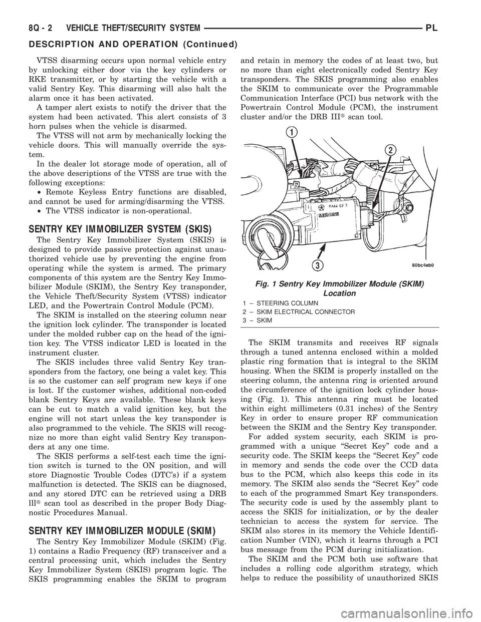
The SKIM is installed on the steering column near
the ignition lock cylinder. The transponder is located
under the molded rubber cap on the head of the igni-
tion key. The VTSS indicator LED is located in the
instrument cluster.
The SKIS includes three valid Sentry Key tran-
sponders from the factory, one being a valet key. This
is so the customer can self program new keys if one
is lost. If the customer wishes, additional non-coded
blank Sentry Keys are available. These blank keys
can be cut to match a valid ignition key, but the
engine will not start unless the key transponder is
also programmed to the vehicle. The SKIS will recog-
nize no more than eight valid Sentry Key transpon-
ders at any one time.
The SKIS performs a self-test each time the igni-
tion switch is turned to the ON position, and will
store Diagnostic Trouble Codes (DTC's) if a system
malfunction is detected. The SKIS can be diagnosed,
and any stored DTC can be retrieved using a DRB
llltscan tool as described in the proper Body Diag-
nostic Procedures Manual.
SENTRY KEY IMMOBILIZER MODULE (SKIM)
The Sentry Key Immobilizer Module (SKIM) (Fig.
1) contains a Radio Frequency (RF) transceiver and a
central processing unit, which includes the Sentry
Key Immobilizer System (SKIS) program logic. The
SKIS programming enables the SKIM to programand retain in memory the codes of at least two, but
no more than eight electronically coded Sentry Key
transponders. The SKIS programming also enables
the SKIM to communicate over the Programmable
Communication Interface (PCI) bus network with the
Powertrain Control Module (PCM), the instrument
cluster and/or the DRB IIItscan tool.
The SKIM transmits and receives RF signals
through a tuned antenna enclosed within a molded
plastic ring formation that is integral to the SKIM
housing. When the SKIM is properly installed on the
steering column, the antenna ring is oriented around
the circumference of the ignition lock cylinder hous-
ing (Fig. 1). This antenna ring must be located
within eight millimeters (0.31 inches) of the Sentry
Key in order to ensure proper RF communication
between the SKIM and the Sentry Key transponder.
For added system security, each SKIM is pro-
grammed with a unique ªSecret Keyº code and a
security code. The SKIM keeps the ªSecret Keyº code
in memory and sends the code over the CCD data
bus to the PCM, which also keeps this code in its
memory. The SKIM also sends the ªSecret Keyº code
to each of the programmed Smart Key transponders.
The security code is used by the assembly plant to
access the SKIS for initialization, or by the dealer
technician to access the system for service. The
SKIM also stores in its memory the Vehicle Identifi-
cation Number (VIN), which it learns through a PCI
bus message from the PCM during initialization.
The SKIM and the PCM both use software that
includes a rolling code algorithm strategy, which
helps to reduce the possibility of unauthorized SKIS
Fig. 1 Sentry Key Immobilizer Module (SKIM)
Location
1 ± STEERING COLUMN
2 ± SKIM ELECTRICAL CONNECTOR
3 ± SKIM
8Q - 2 VEHICLE THEFT/SECURITY SYSTEMPL
DESCRIPTION AND OPERATION (Continued)
Page 374 of 1285
disarming. The rolling code algorithm ensures secu-
rity by preventing an override of the SKIS through
the unauthorized substitution of the SKIM or the
PCM. However, the use of this strategy also means
that replacement of either the SKIM or the PCM
units will require a system initialization procedure to
restore system operation.
When the ignition switch is turned to the ON or
START positions, the SKIM transmits an RF signal
to excite the Sentry Key transponder. The SKIM then
listens for a return RF signal from the transponder
of the Sentry Key that is inserted in the ignition lock
cylinder. If the SKIM receives an RF signal with
valid ªSecret Keyº and transponder identification
codes, the SKIM then sends a ªvalid keyº message to
the PCM over the PCI bus. If the SKIM receives an
invalid RF signal or no response, it sends ªinvalid
keyº messages to the PCM. The PCM will enable or
disable engine operation based upon the status of the
SKIM messages.
The SKIM also sends messages to the instrument
cluster over the PCI bus network to control the VTSS
indicator LED. The SKIM sends messages to the
instrument cluster to turn the LED on for about
three seconds when the ignition switch is turned to
the ON position as a bulb test. After completion of
the bulb test, the SKIM sends bus messages to keep
the LED off for a duration of about one second. Then
the SKIM sends messages to turn the LED on or off
based upon the results of the SKIS self-tests. If the
VTSS indicator LED comes on and stays on after the
bulb test, it indicates that the SKIM has detected a
system malfunction and/or that the SKIS has become
inoperative.
If the SKIM detects an invalid key when the igni-
tion switch is turned to the ON position, it sends
messages to the instrument cluster to flash the VTSS
indicator LED. The SKIM can also send messages to
the instrument cluster to flash the LED and to gen-
erate a single audible chime tone. These functions
serve as an indication to the customer that the SKIS
has been placed in its ªCustomer Learnº program-
ming mode. See Sentry Key Immobilizer System
Transponder Programming in this group for more
information on the ªCustomer Learnº programming
mode.
For diagnosis or initialization of the SKIM and the
PCM, a DRB IIItscan tool and the proper Body
Diagnostic Procedures Manual are required. The
SKIM cannot be repaired, and if faulty or damaged,
the unit must be replaced.
SENTRY KEY IMMOBILIZER SYSTEM
TRANSPONDER
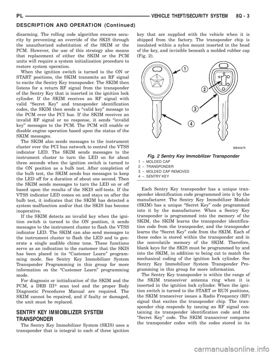
The Sentry Key Immobilizer System (SKIS) uses a
transponder that is integral to each of three ignitionkey that are supplied with the vehicle when it is
shipped from the factory. The transponder chip is
insulated within a nylon mount inserted in the head
of the key, and invisible beneath a molded rubber cap
(Fig. 2).
Each Sentry Key transponder has a unique tran-
sponder identification code programmed into it by the
manufacturer. The Sentry Key Immobilizer Module
(SKIM) has a unique ªSecret Keyº code programmed
into it by the manufacturer. When a Sentry Key
transponder is programmed into the memory of the
SKIM, the SKIM learns the transponder identifica-
tion code from the transponder, and the transponder
learns the ªSecret Keyº code from the SKIM. Each of
these codes is stored within the transponder and in
the nonvolatile memory of the SKIM. Therefore,
blank keys for the SKIS must be programmed by and
into the SKIM, in addition to being cut to match the
mechanical coding of the ignition lock cylinder. See
Sentry Key Immobilizer System Transponder Pro-
gramming in this group for more information.
The Sentry Key transponder is within the range of
the SKIM transceiver antenna ring when it is
inserted in the ignition lock cylinder. When the igni-
tion switch is turned to the START or RUN positions,
the SKIM transceiver issues a Radio Frequency (RF)
signal that excites the transponder chip. The tran-
sponder chip responds by issuing an RF signal con-
taining its transponder identification code and the
ªSecret Keyº code. The SKIM transceiver compares
the transponder codes with the codes stored in its
Fig. 2 Sentry Key Immobilizer Transponder
1 ± MOLDED CAP
2 ± TRANSPONDER
3 ± MOLDED CAP REMOVED
4 ± SENTRY KEY
PLVEHICLE THEFT/SECURITY SYSTEM 8Q - 3
DESCRIPTION AND OPERATION (Continued)
Page 381 of 1285
(6) If window does not move, check to make sure
that it is free to move.
(7) It is necessary that the window be free to slide
up and down in the glass channels. If the window is
not free to move up and down, the window lift motor
will not be able to move the glass.
(8) To determine if the glass is free, disconnect the
regulator from the glass lift plate and slide the win-
dow up and down by hand.
REMOVAL AND INSTALLATION
WINDOW SWITCH
REMOVAL
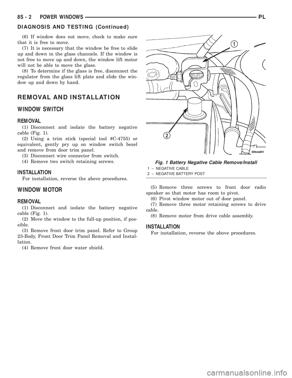
(1) Disconnect and isolate the battery negative
cable (Fig. 1).
(2) Using a trim stick (special tool #C-4755) or
equivalent, gently pry up on window switch bezel
and remove from door trim panel.
(3) Disconnect wire connector from switch.
(4) Remove two switch retaining screws.
INSTALLATION
For installation, reverse the above procedures.
WINDOW MOTOR
REMOVAL
(1) Disconnect and isolate the battery negative
cable (Fig. 1).
(2) Move the window to the full-up position, if pos-
sible.
(3) Remove front door trim panel. Refer to Group
23-Body, Front Door Trim Panel Removal and Instal-
lation.
(4) Remove front door water shield.(5) Remove three screws to front door radio
speaker so that motor has room to pivot.
(6) Pivot window motor out of door panel.
(7) Remove three motor retaining screws to drive
cable.
(8) Remove motor from drive cable assembly.
INSTALLATION
For installation, reverse the above procedures.
Fig. 1 Battery Negative Cable Remove/Install
1 ± NEGATIVE CABLE
2 ± NEGATIVE BATTERY POST
8S - 2 POWER WINDOWSPL
DIAGNOSIS AND TESTING (Continued)