2000 DODGE NEON fuel tank removal
[x] Cancel search: fuel tank removalPage 162 of 1285
WHEEL SPEED SENSOR (REAR)
NOTE: Before proceeding with this procedure,
review SERVICE WARNINGS AND CAUTIONS at the
beginning of REMOVAL AND INSTALLATION in this
section.
REMOVAL
(1) Raise the vehicle. Refer to HOISTING in the
LUBRICATION AND MAINTENANCE group for the
proper lifting procedure.
(2) Remove the tire and wheel assembly from the
vehicle.
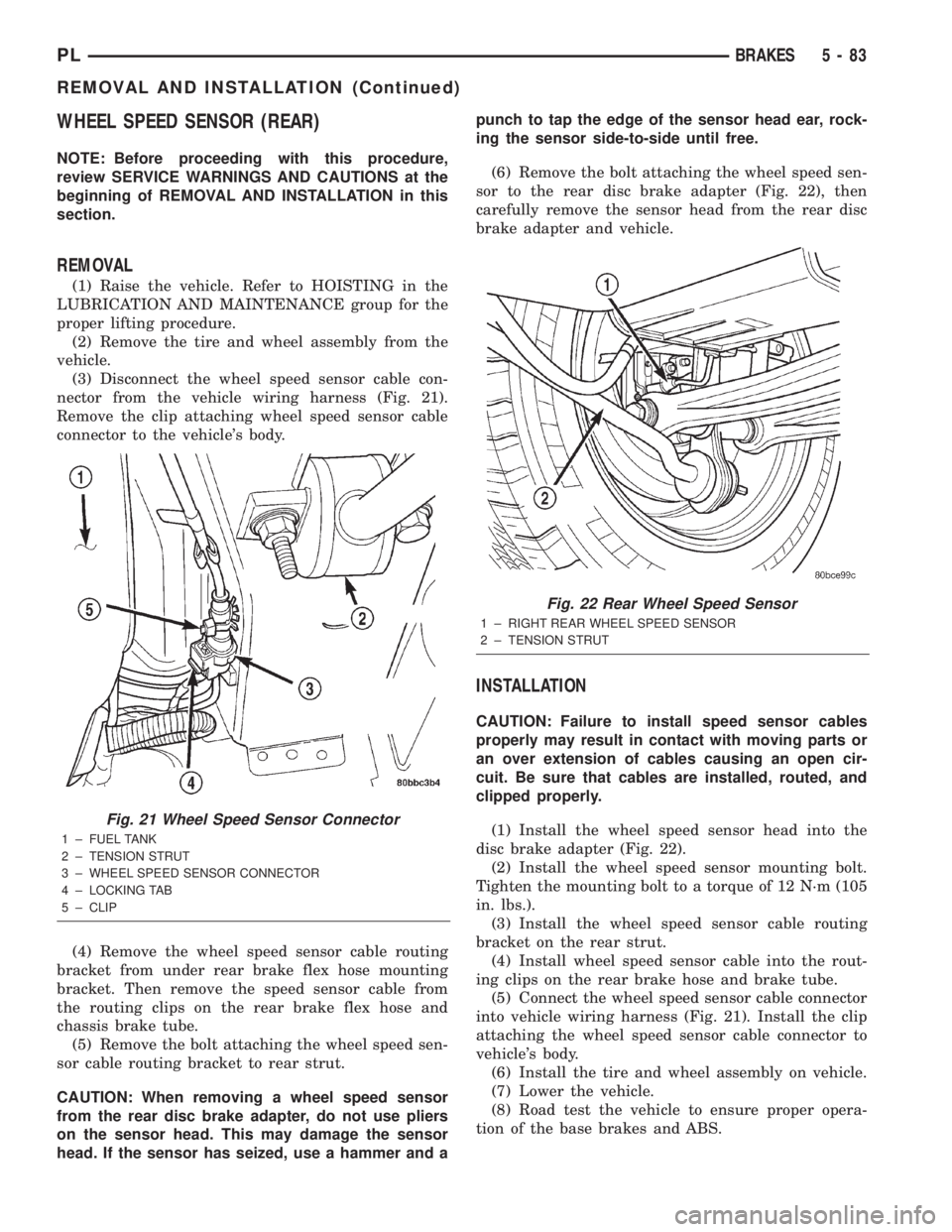
(3) Disconnect the wheel speed sensor cable con-
nector from the vehicle wiring harness (Fig. 21).
Remove the clip attaching wheel speed sensor cable
connector to the vehicle's body.
(4) Remove the wheel speed sensor cable routing
bracket from under rear brake flex hose mounting
bracket. Then remove the speed sensor cable from
the routing clips on the rear brake flex hose and
chassis brake tube.
(5) Remove the bolt attaching the wheel speed sen-
sor cable routing bracket to rear strut.
CAUTION: When removing a wheel speed sensor
from the rear disc brake adapter, do not use pliers
on the sensor head. This may damage the sensor
head. If the sensor has seized, use a hammer and apunch to tap the edge of the sensor head ear, rock-
ing the sensor side-to-side until free.
(6) Remove the bolt attaching the wheel speed sen-
sor to the rear disc brake adapter (Fig. 22), then
carefully remove the sensor head from the rear disc
brake adapter and vehicle.
INSTALLATION
CAUTION: Failure to install speed sensor cables
properly may result in contact with moving parts or
an over extension of cables causing an open cir-
cuit. Be sure that cables are installed, routed, and
clipped properly.
(1) Install the wheel speed sensor head into the
disc brake adapter (Fig. 22).
(2) Install the wheel speed sensor mounting bolt.
Tighten the mounting bolt to a torque of 12 N´m (105
in. lbs.).
(3) Install the wheel speed sensor cable routing
bracket on the rear strut.
(4) Install wheel speed sensor cable into the rout-
ing clips on the rear brake hose and brake tube.
(5) Connect the wheel speed sensor cable connector
into vehicle wiring harness (Fig. 21). Install the clip
attaching the wheel speed sensor cable connector to
vehicle's body.
(6) Install the tire and wheel assembly on vehicle.
(7) Lower the vehicle.
(8) Road test the vehicle to ensure proper opera-
tion of the base brakes and ABS.
Fig. 21 Wheel Speed Sensor Connector
1 ± FUEL TANK
2 ± TENSION STRUT
3 ± WHEEL SPEED SENSOR CONNECTOR
4 ± LOCKING TAB
5 ± CLIP
Fig. 22 Rear Wheel Speed Sensor
1 ± RIGHT REAR WHEEL SPEED SENSOR
2 ± TENSION STRUT
PLBRAKES 5 - 83
REMOVAL AND INSTALLATION (Continued)
Page 804 of 1285
CATALYTIC CONVERTER
REMOVAL
WARNING: THE NORMAL OPERATING TEMPERA-
TURE OF THE EXHAUST SYSTEM IS VERY HIGH.
THEREFORE, NEVER ATTEMPT TO SERVICE ANY
PART OF THE EXHAUST SYSTEM UNTIL IT IS
COOLED. SPECIAL CARE SHOULD BE TAKEN
WHEN WORKING NEAR THE CATALYTIC CON-
VERTER. THE TEMPERATURE OF THE CONVERTER
RISES TO A HIGH LEVEL AFTER A SHORT PERIOD
OF ENGINE OPERATION TIME.
NOTE: Vehicles equipped with the ULEV emission
package are equipped with an additional catalytic
converter that is integral to the exhaust manifold.
Refer to Exhaust Manifold in Group 9, Engine for
procedure.
(1) Remove muffler and exhaust pipe. Refer to pro-
cedure in this section.
(2) Disconnect downstream oxygen sensor electri-
cal connector.
(3) Remove exhaust manifold support bracket
(Federal and LEV only) (Fig. 10).
(4) Remove catalytic converter to exhaust manifold
attaching fasteners and remove converter from vehi-
cle (Fig. 11) or (Fig. 12).
(5) Remove and discard flange gasket.
NOTE: When replacement is required on any com-
ponent of the exhaust system, original equipment
parts (or equivalent) must be used.
INSTALLATION
NOTE: When assembling exhaust system do not
tighten clamps until all components are aligned and
clearances are checked.(1) Assemble catalytic converter to exhaust mani-
fold connection. Use a new flange gasket.
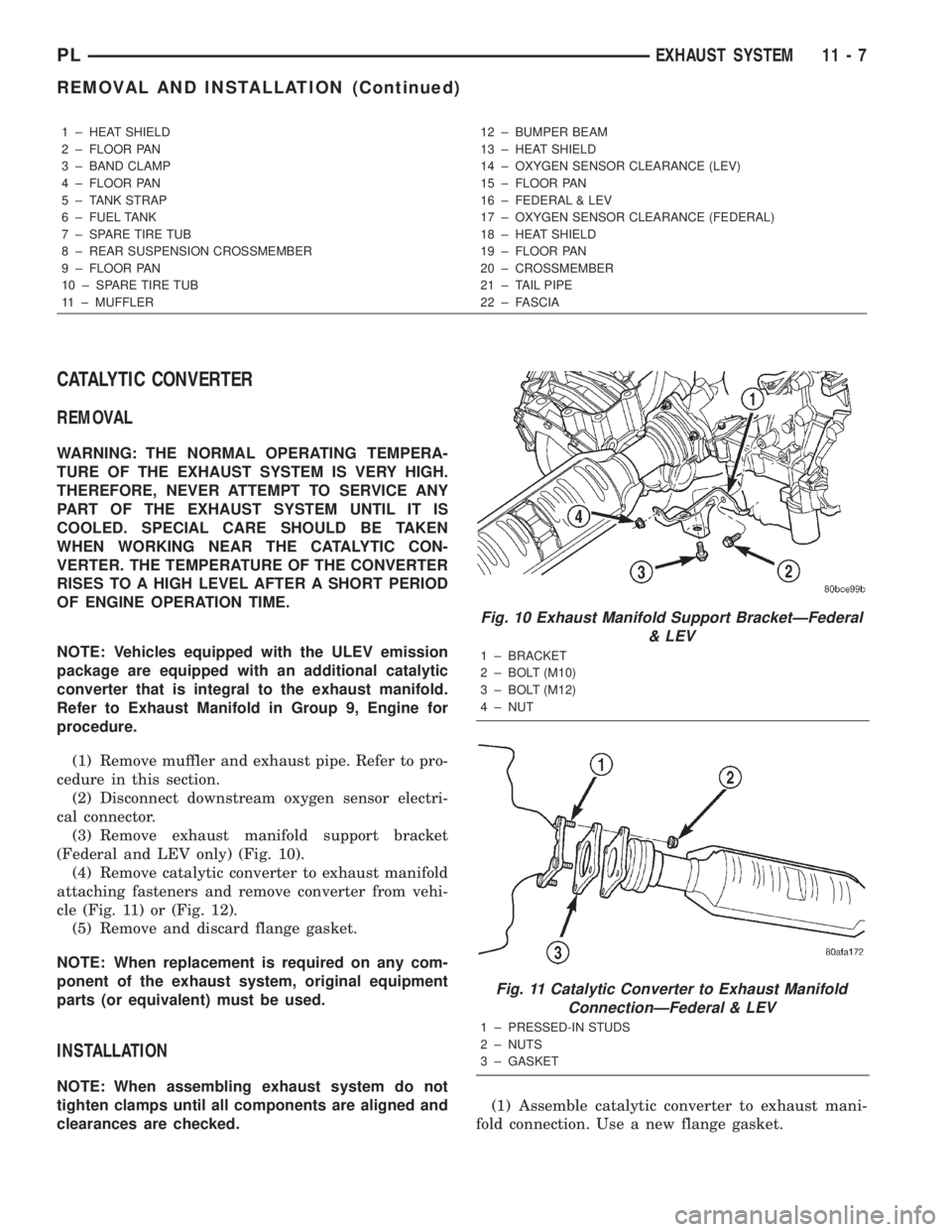
1 ± HEAT SHIELD
2 ± FLOOR PAN
3 ± BAND CLAMP
4 ± FLOOR PAN
5 ± TANK STRAP
6 ± FUEL TANK
7 ± SPARE TIRE TUB
8 ± REAR SUSPENSION CROSSMEMBER
9 ± FLOOR PAN
10 ± SPARE TIRE TUB
11 ± MUFFLER12 ± BUMPER BEAM
13 ± HEAT SHIELD
14 ± OXYGEN SENSOR CLEARANCE (LEV)
15 ± FLOOR PAN
16 ± FEDERAL & LEV
17 ± OXYGEN SENSOR CLEARANCE (FEDERAL)
18 ± HEAT SHIELD
19 ± FLOOR PAN
20 ± CROSSMEMBER
21 ± TAIL PIPE
22 ± FASCIA
Fig. 10 Exhaust Manifold Support BracketÐFederal
& LEV
1 ± BRACKET
2 ± BOLT (M10)
3 ± BOLT (M12)
4 ± NUT
Fig. 11 Catalytic Converter to Exhaust Manifold
ConnectionÐFederal & LEV
1 ± PRESSED-IN STUDS
2 ± NUTS
3 ± GASKET
PLEXHAUST SYSTEM 11 - 7
REMOVAL AND INSTALLATION (Continued)
Page 822 of 1285
FUEL SYSTEM
TABLE OF CONTENTS
page page
FUEL DELIVERY SYSTEM.................... 1FUEL INJECTION SYSTEM.................. 21
FUEL DELIVERY SYSTEM
TABLE OF CONTENTS
page page
DESCRIPTION AND OPERATION
FUEL REQUIREMENTS.....................1
GASOLINE/OXYGENATE BLENDS.............2
FUEL DELIVERY SYSTEM...................3
FUEL PUMP MODULE......................3
ELECTRIC FUEL PUMP.....................4
FUEL GAUGE SENDING UNIT................4
FUEL FILTER/FUEL PRESSURE REGULATOR....4
FUEL TANK..............................4
FUEL RAIL...............................4
FUEL INJECTORS.........................5
PRESSURE-VACUUM FILLER CAP............5
ONBOARD REFUELING VAPOR RECOVERY....6
CONTROL VALVE/PRESSURE RELIEF.........6
QUICK-CONNECT FITTINGS.................6
ROLLOVER VALVES.......................7
FUEL TUBES/LINES/HOSES AND CLAMPS......8
SERVICE PROCEDURES
FUEL SYSTEM PRESSURE RELEASE
PROCEDURE...........................8INJECTOR CONNECTOR....................8
DRAINING FUEL TANK.....................9
HOSES AND CLAMPS......................9
QUICK-CONNECT FITTINGS.................9
REMOVAL AND INSTALLATION
AUTOMATIC SHUTDOWN RELAY............12
FUEL PUMP RELAY.......................12
FUEL PUMP MODULE.....................12
FUEL FILTER / PRESSURE REGULATOR......13
FUEL PUMP INLET STRAINER..............14
FUEL LEVEL SENSOR.....................14
FUEL INJECTORS........................15
FUEL TANK.............................16
FUEL FILLER NECK.......................17
ACCELERATOR PEDAL....................18
THROTTLE CABLE.......................19
SPECIFICATIONS
TORQUE...............................20
DESCRIPTION AND OPERATION
FUEL REQUIREMENTS
OPERATION
Your engine is designed to meet all emissions reg-
ulations and provide excellent fuel economy and per-
formance when using high quality unleaded gasoline
having an octane rating of 87. The use of premium
gasoline is not recommended. The use of premium
gasoline will provide no benefit over high quality reg-
ular gasoline, and in some circumstances may result
in poorer performance.
Light spark knock at low engine speeds is not
harmful to your engine. However, continued heavyspark knock at high speeds can cause damage and
immediate service is required. Engine damage result-
ing from operation with a heavy spark knock may
not be covered by the new vehicle warranty.
Poor quality gasoline can cause problems such as
hard starting, stalling and hesitations. If you experi-
ence these symptoms, try another brand of gasoline
before considering service for the vehicle.
The American Automobile Manufacturers Associa-
tion, AAMA, has issued gasoline specifications to
define the minimum fuel properties necessary to
deliver enhanced performance and durability for your
vehicle. DaimlerChrysler Corporation recommends
the use of gasoline that meet the AAMA specifica-
tions if they are available.
PLFUEL SYSTEM 14 - 1
Page 824 of 1285
carbon monoxide emissions. The type and amount of
oxygenate used in the blend is important.
The following are generally used in gasoline
blends:
Ethanol- (Ethyl or Grain Alcohol) properly
blended, is used as a mixture of 10 percent ethanol
and 90 percent gasoline. Gasoline blended with etha-
nol may be used in your vehicle.
MTBE/ETBE- Gasoline and MTBE (Methyl Ter-
tiary Butyl Ether) blends are a mixture of unleaded
gasoline and up to 15 percent MTBE. Gasoline and
ETBE (Ethyl Tertiary Butyl Ether) are blends of gas-
oline and up to 17 percent ETBE. Gasoline blended
with MTBE or ETBE may be used in your vehicle.
Methanol- Methanol (Methyl or Wood Alcohol) is
used in a variety of concentrations blended with
unleaded gasoline. You may encounter fuels contain-
ing 3 percent or more methanol along with other
alcohols called cosolvents.
DO NOT USE GASOLINE CONTAINING
METHANOL.
Use of methanol/gasoline blends may result in
starting and driveability problems and damage criti-
cal fuel system components.
Problems that are the result of using methanol/
gasoline blends are not the responsibility of
DaimlerChrysler Corporation and may not be covered
by the vehicle warranty.
Reformulated Gasoline
Many areas of the country are requiring the use of
cleaner-burning fuel referred to asReformulated
Gasoline. Reformulated gasoline are specially
blended to reduce vehicle emissions and improve air
quality.
DaimlerChrysler Corporation strongly supports the
use of reformulated gasoline whenever available.
Although your vehicle was designed to provide opti-
mum performance and lowest emissions operating on
high quality unleaded gasoline, it will perform
equally well and produce even lower emissions when
operating on reformulated gasoline.
Materials Added to Fuel
Indiscriminate use of fuel system cleaning agents
should be avoided. Many of these materials intended
for gum and varnish removal may contain active sol-
vents of similar ingredients that can be harmful to
fuel system gasket and diaphragm materials.
FUEL DELIVERY SYSTEM
OPERATION
The fuel delivery system consists of: the electric
fuel pump, fuel filter/fuel pressure regulator, fuel
tubes/lines/hoses, fuel rail, fuel injectors, fuel tank,
accelerator pedal and throttle cable.A fuel return system is used on all models (all
engines). Fuel is returned through the fuel pump
module and back into the fuel tank through the fuel
filter/fuel pressure regulator. A separate fuel return
line from the engine to the tank is no longer used
with any engine.
The fuel tank assembly consists of: the fuel tank,
filler tube, fuel gauge sending unit/electric fuel pump
module, a rollover valve(s) and a pressure-vacuum
filler cap.
Also to be considered part of the fuel system is the
evaporation control system or Onboard Refueling
Vapor recovery (ORVR). This is designed to reduce
the emission of fuel vapors into the atmosphere. The
description and function of the Evaporative Control
System is found in the Emission Control Systems
section.
FUEL PUMP MODULE
DESCRIPTION
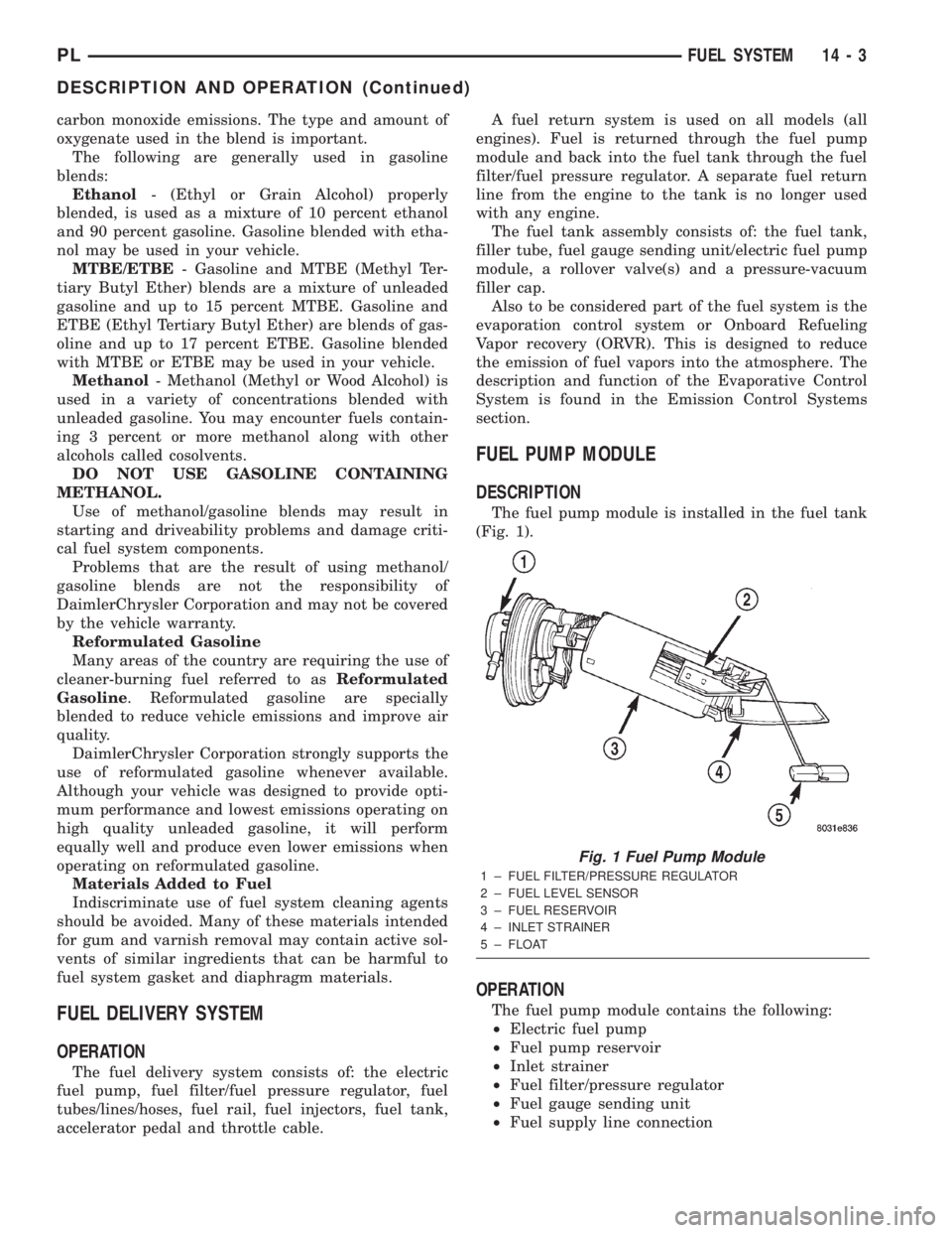
The fuel pump module is installed in the fuel tank
(Fig. 1).
OPERATION
The fuel pump module contains the following:
²Electric fuel pump
²Fuel pump reservoir
²Inlet strainer
²Fuel filter/pressure regulator
²Fuel gauge sending unit
²Fuel supply line connection
Fig. 1 Fuel Pump Module
1 ± FUEL FILTER/PRESSURE REGULATOR
2 ± FUEL LEVEL SENSOR
3 ± FUEL RESERVOIR
4 ± INLET STRAINER
5 ± FLOAT
PLFUEL SYSTEM 14 - 3
DESCRIPTION AND OPERATION (Continued)
Page 827 of 1285
WARNING: REMOVE FILLER CAP TO RELIEVE
TANK PRESSURE BEFORE REMOVING OR REPAIR-
ING FUEL SYSTEM COMPONENTS.
ONBOARD REFUELING VAPOR RECOVERY
OPERATION
The emission control principle used in the ORVR
system is that the fuel flowing into the filler tube
(appx. 1º I. D.) creates an aspiration effect which
draws air into the fill tube. During refueling, the fuel
tank is vented to the vapor canister to capture escap-
ing vapors. With air flowing into the filler tube, there
are no fuel vapors escaping to the atmosphere. Once
the refueling vapors are captured by the canister, the
vehicle's computer controlled purge system draws
vapor out of the canister for the engine to burn. The
vapors flow is metered by the purge solenoid so that
there is no or minimal impact on driveability or
tailpipe emissions.
As fuel starts to flow through the fill tube, it opens
the normally closed check valve and enters the fuel
tank. Vapor or air is expelled from the tank through
the control valve to the vapor canister. Vapor is
absorbed in the canister until vapor flow in the lines
stops, either following shut-off or by having the fuel
level in the tank rise high enough to close the control
valve. The control valve contains a float that rises to
seal the large diameter vent path to the canister. At
this point in the fueling of the vehicle, the tank pres-
sure increase, the check valve closes (preventing tank
fuel from spiting back at the operator), and fuel then
rises up the filler tube to shut-off the dispensing noz-
zle.If the engine is shut-off while the On-Board diag-
nostics test is running, low level tank pressure can
be trapped in the fuel tank and fuel can not be added
to the tank until the pressure is relieved. This is due
to the leak detection pump closing the vapor outlet
from the top of the tank and the one-way check valve
not allowing the tank to vent through the fill tube to
atmosphere. Therefore, when fuel is added, it will
back-up in the fill tube and shut off the dispensing
nozzle. The pressure can be eliminated in two ways:
1. Vehicle purge must be activated and for a long
enough period to eliminate the pressure. 2. Removing
the fuel cap and allowing enough time for the system
to vent thru the recirulation tube.
CONTROL VALVE/PRESSURE RELIEF
OPERATION
If the fuel tank should over-pressurize, the control
valve incorporates a pressure relief port that allows
pressure relief capability under extreme conditions.
Example, if the canister vent line was to get pinched
or obstructed, the relief valve would vent the pres-
sure.
QUICK-CONNECT FITTINGS
DESCRIPTION
Different types of quick-connect fittings are used to
attach various fuel system components. These are: a
single-tab type, a two-tab type or a plastic retainer
ring type. Some are equipped with safety latch clips.
Refer to the Removal/Installation section for more
information.
CAUTION: The interior components (o-rings, spac-
ers) of quick-connect fitting are not serviced sepa-
rately. Do not attempt to repair damaged fittings or
fuel lines/tubes. If repair is necessary, replace the
complete fuel tube assembly.
Fuel tubes connect fuel system components with
plastic quick-connect fuel fittings. The fitting con-
tains non-serviceable O-ring seals (Fig. 6).
CAUTION: Quick-connect fittings are not serviced
separately. Do not attempt to repair damaged quick-
connect fittings or fuel tubes. Replace the complete
fuel tube/quick-connect fitting assembly.
The quick-connect fitting consists of the O-rings,
retainer and casing (Fig. 6). When the fuel tube
enters the fitting, the retainer locks the shoulder of
the nipple in place and the O-rings seal the tube.
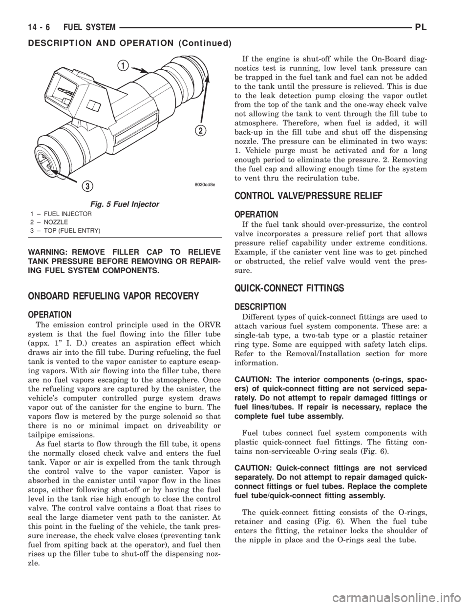
Fig. 5 Fuel Injector
1 ± FUEL INJECTOR
2 ± NOZZLE
3 ± TOP (FUEL ENTRY)
14 - 6 FUEL SYSTEMPL
DESCRIPTION AND OPERATION (Continued)
Page 830 of 1285
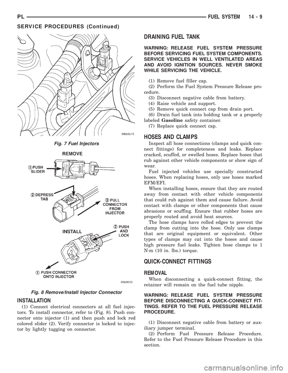
INSTALLATION
(1) Connect electrical connectors at all fuel injec-
tors. To install connector, refer to (Fig. 8). Push con-
nector onto injector (1) and then push and lock red
colored slider (2). Verify connector is locked to injec-
tor by lightly tugging on connector.
DRAINING FUEL TANK
WARNING: RELEASE FUEL SYSTEM PRESSURE
BEFORE SERVICING FUEL SYSTEM COMPONENTS.
SERVICE VEHICLES IN WELL VENTILATED AREAS
AND AVOID IGNITION SOURCES. NEVER SMOKE
WHILE SERVICING THE VEHICLE.
(1) Remove fuel filler cap.
(2) Perform the Fuel System Pressure Release pro-
cedure.
(3) Disconnect negative cable from battery.
(4) Raise vehicle and support.
(5) Remove quick connect cap from drain port.
(6) Drain fuel tank into holding tank or a properly
labeledGasolinesafety container.
(7) Replace quick connect cap.
HOSES AND CLAMPS
Inspect all hose connections (clamps and quick con-
nect fittings) for completeness and leaks. Replace
cracked, scuffed, or swelled hoses. Replace hoses that
rub against other vehicle components or show sign of
wear.
Fuel injected vehicles use specially constructed
hoses. When replacing hoses, only use hoses marked
EFM/EFI.
When installing hoses, ensure that they are routed
away from contact with other vehicle components
that could rub against them and cause failure. Avoid
contact with clamps or other components that cause
abrasions or scuffing. Ensure that rubber hoses are
properly routed and avoid heat sources.
The hose clamps have rolled edges to prevent the
clamp from cutting into the hose. Only use clamps
that are original equipment or equivalent. Other
types of clamps may cut into the hoses and cause
high pressure fuel leaks. Tighten hose clamps to 1
N´m (10 in. lbs.) torque.
QUICK-CONNECT FITTINGS
REMOVAL
When disconnecting a quick-connect fitting, the
retainer will remain on the fuel tube nipple.
WARNING: RELEASE FUEL SYSTEM PRESSURE
BEFORE DISCONNECTING A QUICK-CONNECT FIT-
TINGS. REFER TO THE FUEL PRESSURE RELEASE
PROCEDURE.
(1) Disconnect negative cable from battery or aux-
iliary jumper terminal.
(2) Perform Fuel Pressure Release Procedure.
Refer to the Fuel Pressure Release Procedure in this
section.
Fig. 7 Fuel Injectors
Fig. 8 Remove/Install Injector Connector
PLFUEL SYSTEM 14 - 9
SERVICE PROCEDURES (Continued)
Page 833 of 1285

REMOVAL AND INSTALLATION
AUTOMATIC SHUTDOWN RELAY
The relay is located in the Power Distribution Cen-
ter (PDC) (Fig. 12). The PDC is located next to the
battery in the engine compartment. For the location
of the relay within the PDC, refer to the PDC cover
for location. Check electrical terminals for corrosion
and repair as necessary.
FUEL PUMP RELAY
The fuel pump relay is located in the PDC. The
inside top of the PDC cover has a label showing relay
and fuse location.
FUEL PUMP MODULE
REMOVAL
WARNING: RELEASE FUEL SYSTEM PRESSURE
BEFORE SERVICING FUEL SYSTEM COMPONENTS.
SERVICE VEHICLES IN WELL VENTILATED AREAS
AND AVOID IGNITION SOURCES. NEVER SMOKE
WHILE SERVICING THE VEHICLE.
(1) Drain the fuel. Refer to Draining Fuel Tank in
the Fuel Tank section of this group.
WARNING: THE FUEL RESERVOIR OF THE FUEL
PUMP MODULE DOES NOT EMPTY OUT WHEN THE
TANK IS DRAINED. THE FUEL IN THE RESERVOIR
WILL SPILL OUT WHEN THE MODULE IS
REMOVED.
(2) Remove fuel tank, refer to the Fuel Tank
removal/installation section.
(3) Lower tank.(4) Use Special Tool 6856 to remove fuel pump
module locknut (Fig. 15).
(5) Remove fuel pump and O-ring seal from tank.
Discard old seal.
INSTALLATION
(1) Wipe seal area of tank clean and place a new
seal in position in the tank opening.
(2) Position fuel pump in the tank. Make sure the
alignment tab on the underside of the fuel pump
module flange sits in the notch on the fuel tank (Fig.
14).
(3) Position the locknut over the fuel pump mod-
ule.
Fig. 12 Power Distribution Center (PDC)
Fig. 13 Fuel Pump Module Removal
1 ± FUEL FILTER/PRESSURE REGULATOR
2 ± FUEL LINE
3 ± LOCKNUT
Fig. 14 Alignment Tab
14 - 12 FUEL SYSTEMPL
Page 834 of 1285
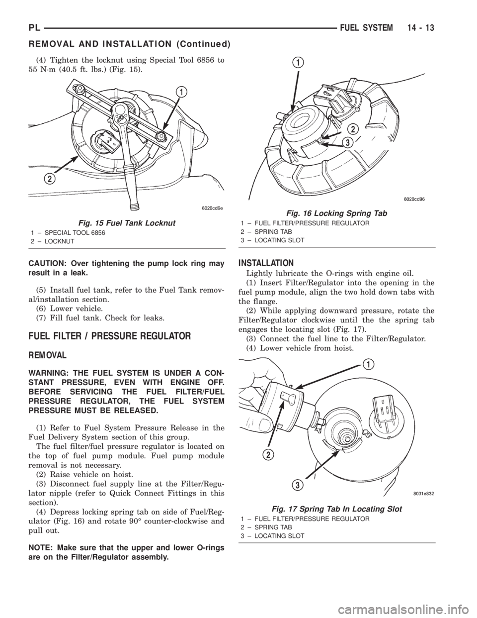
(4) Tighten the locknut using Special Tool 6856 to
55 N´m (40.5 ft. lbs.) (Fig. 15).
CAUTION: Over tightening the pump lock ring may
result in a leak.
(5) Install fuel tank, refer to the Fuel Tank remov-
al/installation section.
(6) Lower vehicle.
(7) Fill fuel tank. Check for leaks.
FUEL FILTER / PRESSURE REGULATOR
REMOVAL
WARNING: THE FUEL SYSTEM IS UNDER A CON-
STANT PRESSURE, EVEN WITH ENGINE OFF.
BEFORE SERVICING THE FUEL FILTER/FUEL
PRESSURE REGULATOR, THE FUEL SYSTEM
PRESSURE MUST BE RELEASED.
(1) Refer to Fuel System Pressure Release in the
Fuel Delivery System section of this group.
The fuel filter/fuel pressure regulator is located on
the top of fuel pump module. Fuel pump module
removal is not necessary.
(2) Raise vehicle on hoist.
(3) Disconnect fuel supply line at the Filter/Regu-
lator nipple (refer to Quick Connect Fittings in this
section).
(4) Depress locking spring tab on side of Fuel/Reg-
ulator (Fig. 16) and rotate 90É counter-clockwise and
pull out.
NOTE: Make sure that the upper and lower O-rings
are on the Filter/Regulator assembly.
INSTALLATION
Lightly lubricate the O-rings with engine oil.
(1) Insert Filter/Regulator into the opening in the
fuel pump module, align the two hold down tabs with
the flange.
(2) While applying downward pressure, rotate the
Filter/Regulator clockwise until the the spring tab
engages the locating slot (Fig. 17).
(3) Connect the fuel line to the Filter/Regulator.
(4) Lower vehicle from hoist.
Fig. 15 Fuel Tank Locknut
1 ± SPECIAL TOOL 6856
2 ± LOCKNUT
Fig. 16 Locking Spring Tab
1 ± FUEL FILTER/PRESSURE REGULATOR
2 ± SPRING TAB
3 ± LOCATING SLOT
Fig. 17 Spring Tab In Locating Slot
1 ± FUEL FILTER/PRESSURE REGULATOR
2 ± SPRING TAB
3 ± LOCATING SLOT
PLFUEL SYSTEM 14 - 13
REMOVAL AND INSTALLATION (Continued)