2000 DODGE NEON ECO mode
[x] Cancel search: ECO modePage 146 of 1285
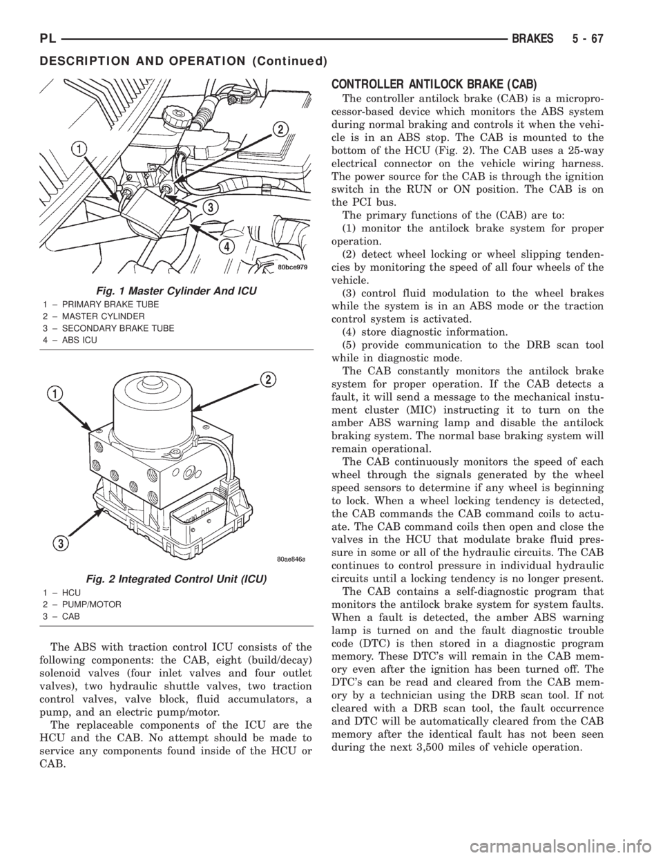
The ABS with traction control ICU consists of the
following components: the CAB, eight (build/decay)
solenoid valves (four inlet valves and four outlet
valves), two hydraulic shuttle valves, two traction
control valves, valve block, fluid accumulators, a
pump, and an electric pump/motor.
The replaceable components of the ICU are the
HCU and the CAB. No attempt should be made to
service any components found inside of the HCU or
CAB.
CONTROLLER ANTILOCK BRAKE (CAB)
The controller antilock brake (CAB) is a micropro-
cessor-based device which monitors the ABS system
during normal braking and controls it when the vehi-
cle is in an ABS stop. The CAB is mounted to the
bottom of the HCU (Fig. 2). The CAB uses a 25-way
electrical connector on the vehicle wiring harness.
The power source for the CAB is through the ignition
switch in the RUN or ON position. The CAB is on
the PCI bus.
The primary functions of the (CAB) are to:
(1) monitor the antilock brake system for proper
operation.
(2) detect wheel locking or wheel slipping tenden-
cies by monitoring the speed of all four wheels of the
vehicle.
(3) control fluid modulation to the wheel brakes
while the system is in an ABS mode or the traction
control system is activated.
(4) store diagnostic information.
(5) provide communication to the DRB scan tool
while in diagnostic mode.
The CAB constantly monitors the antilock brake
system for proper operation. If the CAB detects a
fault, it will send a message to the mechanical instu-
ment cluster (MIC) instructing it to turn on the
amber ABS warning lamp and disable the antilock
braking system. The normal base braking system will
remain operational.
The CAB continuously monitors the speed of each
wheel through the signals generated by the wheel
speed sensors to determine if any wheel is beginning
to lock. When a wheel locking tendency is detected,
the CAB commands the CAB command coils to actu-
ate. The CAB command coils then open and close the
valves in the HCU that modulate brake fluid pres-
sure in some or all of the hydraulic circuits. The CAB
continues to control pressure in individual hydraulic
circuits until a locking tendency is no longer present.
The CAB contains a self-diagnostic program that
monitors the antilock brake system for system faults.
When a fault is detected, the amber ABS warning
lamp is turned on and the fault diagnostic trouble
code (DTC) is then stored in a diagnostic program
memory. These DTC's will remain in the CAB mem-
ory even after the ignition has been turned off. The
DTC's can be read and cleared from the CAB mem-
ory by a technician using the DRB scan tool. If not
cleared with a DRB scan tool, the fault occurrence
and DTC will be automatically cleared from the CAB
memory after the identical fault has not been seen
during the next 3,500 miles of vehicle operation.
Fig. 1 Master Cylinder And ICU
1 ± PRIMARY BRAKE TUBE
2 ± MASTER CYLINDER
3 ± SECONDARY BRAKE TUBE
4 ± ABS ICU
Fig. 2 Integrated Control Unit (ICU)
1 ± HCU
2 ± PUMP/MOTOR
3 ± CAB
PLBRAKES 5 - 67
DESCRIPTION AND OPERATION (Continued)
Page 150 of 1285
If the CAB calculates that the brake temperatures
are high, the traction control system becomes inoper-
ative until a time-out period has elapsed. During this
ªthermo-protection mode,º the traction control func-
tion lamp illuminates TRAC OFF; note that no trou-
ble code is registered.
HYDRAULIC CIRCUITS AND VALVE OPERATION
The hydraulic shuttle valves control the flow of
pressurized brake fluid to the wheel brakes during
the different modes of ABS braking. The following
paragraphs explain how this works. For purposes of
explanation only, it is assumed that only the right
front wheel is experiencing antilock braking; the fol-
lowing diagrams show only the right front wheel in
an antilock braking operation.
NORMAL BRAKING HYDRAULIC CIRCUIT,
SOLENOID VALVE, AND SHUTTLE VALVE
FUNCTION (ABS WITH TRACTION CONTROL)
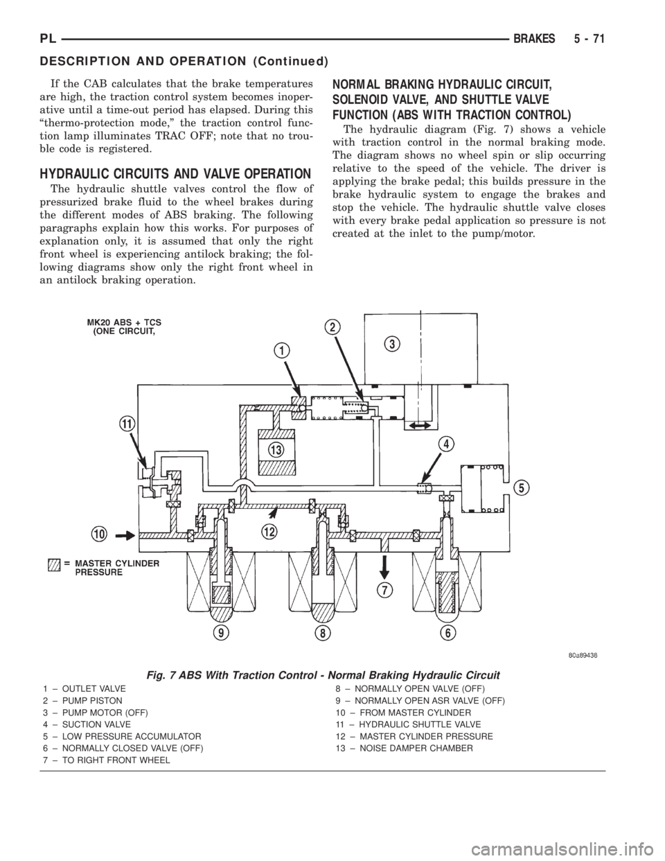
The hydraulic diagram (Fig. 7) shows a vehicle
with traction control in the normal braking mode.
The diagram shows no wheel spin or slip occurring
relative to the speed of the vehicle. The driver is
applying the brake pedal; this builds pressure in the
brake hydraulic system to engage the brakes and
stop the vehicle. The hydraulic shuttle valve closes
with every brake pedal application so pressure is not
created at the inlet to the pump/motor.
Fig. 7 ABS With Traction Control - Normal Braking Hydraulic Circuit
1 ± OUTLET VALVE
2 ± PUMP PISTON
3 ± PUMP MOTOR (OFF)
4 ± SUCTION VALVE
5 ± LOW PRESSURE ACCUMULATOR
6 ± NORMALLY CLOSED VALVE (OFF)
7 ± TO RIGHT FRONT WHEEL8 ± NORMALLY OPEN VALVE (OFF)
9 ± NORMALLY OPEN ASR VALVE (OFF)
10 ± FROM MASTER CYLINDER
11 ± HYDRAULIC SHUTTLE VALVE
12 ± MASTER CYLINDER PRESSURE
13 ± NOISE DAMPER CHAMBER
PLBRAKES 5 - 71
DESCRIPTION AND OPERATION (Continued)
Page 184 of 1285
RADIATOR HOSES AND CLAMPS
WARNING: IF VEHICLE HAS BEEN RUN RECENTLY,
WAIT 15 MINUTES BEFORE WORKING ON VEHI-
CLE. RELIEVE PRESSURE BY PLACING A SHOP
TOWEL OVER THE CAP AND WITHOUT PUSHING
DOWN ROTATE IT COUNTERCLOCKWISE TO THE
FIRST STOP. ALLOW FLUIDS TO ESCAPE
THROUGH THE OVERFLOW TUBE AND WHEN THE
SYSTEM STOPS PUSHING OUT COOLANT AND
STEAM AND THE PRESSURE DROPS CONTINUE
SERVICE.
WARNING: CONSTANT TENSION HOSE CLAMPS
ARE USED ON MOST COOLING SYSTEM HOSES.
WHEN REMOVING OR INSTALLING, USE ONLY
TOOLS DESIGNED FOR SERVICING THIS TYPE OF
CLAMP. ALWAYS WEAR SAFETY GLASSES WHEN
SERVICING CONSTANT TENSION CLAMPS.
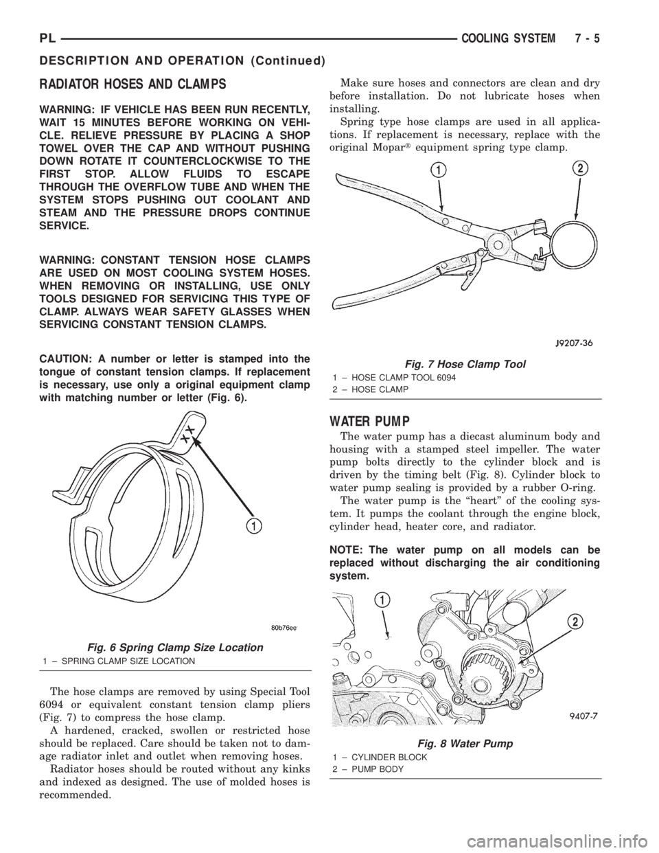
CAUTION: A number or letter is stamped into the
tongue of constant tension clamps. If replacement
is necessary, use only a original equipment clamp
with matching number or letter (Fig. 6).
The hose clamps are removed by using Special Tool
6094 or equivalent constant tension clamp pliers
(Fig. 7) to compress the hose clamp.
A hardened, cracked, swollen or restricted hose
should be replaced. Care should be taken not to dam-
age radiator inlet and outlet when removing hoses.
Radiator hoses should be routed without any kinks
and indexed as designed. The use of molded hoses is
recommended.Make sure hoses and connectors are clean and dry
before installation. Do not lubricate hoses when
installing.
Spring type hose clamps are used in all applica-
tions. If replacement is necessary, replace with the
original Mopartequipment spring type clamp.
WATER PUMP
The water pump has a diecast aluminum body and
housing with a stamped steel impeller. The water
pump bolts directly to the cylinder block and is
driven by the timing belt (Fig. 8). Cylinder block to
water pump sealing is provided by a rubber O-ring.
The water pump is the ªheartº of the cooling sys-
tem. It pumps the coolant through the engine block,
cylinder head, heater core, and radiator.
NOTE: The water pump on all models can be
replaced without discharging the air conditioning
system.
Fig. 6 Spring Clamp Size Location
1 ± SPRING CLAMP SIZE LOCATION
Fig. 7 Hose Clamp Tool
1 ± HOSE CLAMP TOOL 6094
2 ± HOSE CLAMP
Fig. 8 Water Pump
1 ± CYLINDER BLOCK
2 ± PUMP BODY
PLCOOLING SYSTEM 7 - 5
DESCRIPTION AND OPERATION (Continued)
Page 249 of 1285
DESCRIPTION AND OPERATION
HEADLAMP SWITCH
The headlamp switch is part of the Multi-Function
Switch. Refer to Group 8J, Turn Signal and Flasher
for the Multi-Function Switch Test, Removal and
Installation procedures.
INSTRUMENT CLUSTER
There are two conventional instrument cluster
assemblies available. The clusters electronically drive
the speedometer, odometer, gauges, and tachometer
(if equipped). Refer to (Fig. 2) and (Fig. 3).
The instrument cluster controls the courtesy
lamps, it receives and sends messages to other mod-
ules via the PCI bus circuit, it controls all the instru-
ment illumination and the chime is also an integral
part of the cluster. The front turn signals are wired
through the cluster and then go to the front lamps.
The reason being that the DRL module is built into
the cluster (if equipped).
All gauges in the electronic clusters are the analog
type gauges. When the ignition switch is moved to
the OFF position, the cluster drives each gauge to its
lowest position. The individual gauges are not servi-
cable and require complete replacement of the cluster
if one or more gauges are inoperable.
One button is used to switch the display from trip
to total mileage. Holding the button when the display
is in the trip mode will reset the trip mileage. This
button is also used to put the cluster in self-diagnos-
tic mode. Refer to Service Procedures, Cluster Self-
Diagnostics in this section. Most of the indicators will
come on briefly for a bulb heck when the ignition is
turned from OFF to ON. All of the LED's are replace-
able.
In the event that the instrument cluster looses
communication with all other modules on the PCI
bus, the cluster will display ªnobusº in the VF dis-
play. The VF display also displays ªDoorº, ªCruiseº,
ªTracº, and odometer trip or total.
If the cluster does not detect voltage on the cour-
tesy lamp circuit, the message ªFUSEº will alternate
with the odometer/trip odometer for 30 seconds after
the ignition is turned on and for 15 seconds after the
vehicle is first moved. The lack of voltage can be due
to the M1 Fused B(+) (IOD) fuse being open, a bad or
missing courtesy lamp bulb, or a circuit problem.
WARNING AND INDICATOR LAMPS
The instrument cluster has warning lamps and
indicators for the following systems:
²Airbag
²Anti-lock Brakes (ABS) if equipped
²Brake warning
²Charging System²Front fog lamps (if equipped)
²High beam indicator
²Low fuel (premium cluster only)
²Low oil pressure
²Malfunction indicator (service engine soon) lamp
²Right and left turn signals
²Seat belt warning
²Security system
²Trac-Off (ABS equipped vehicles only)
The instrument cluster has a Vacuum Fluorescent
(VF) display for the following systems:
²Cruise
²Door (ajar)
²Odometer
²Set (cruise)
²Trac
²Trip
DIAGNOSIS AND TESTING
AIRBAG WARNING SYSTEM
For testing of this system refer to Group 8M, Pas-
sive Restraint Systems.
BRAKE SYSTEM WARNING LAMP TEST
The brake warning lamp illuminates when the
parking brake is applied with ignition switch turned
to the ON position. The same lamp will also illumi-
nate if one of the two service brake systems fail the
when brake pedal is applied.
To test the system:
²As the ignition switch is turned to the start posi-
tion the lamp should light.
²Turn ignition switch to the ON position and
apply the parking brake. The lamp should light.
If lamp fails to light inspect for:
²A burned out lamp
²Loose, corroded or damaged socket
²A damaged circuit board
²A broken or disconnected wire at the switch
²Defective switch
To test the service brake warning system, refer to
Group 5, Brakes, Hydraulic System Control Valves.
INSTRUMENT CLUSTER LAMPS
Every time the vehicle is switched to the START/
RUN position, the cluster goes through a BULB
CHECK. This tests most of the indicator lamps and
Vacuum Fluorescent (VF) displays. If only one lamp
is out, remove the instrument cluster and replace the
defective bulb or Light Emitting Diode (LED). If
some or all of the lamps fail to light, refer to the
proper Body Diagnostics Procedures Manual.
8E - 2 INSTRUMENT PANEL SYSTEMSPL
Page 287 of 1285
SPEED CONTROL SERVO-PCM OUTPUT
DESCRIPTION
The servo unit consists of a solenoid valve body,
and a vacuum chamber. The solenoid valve body con-
tains three solenoids:
²Vacuum
²Vent
²Dump
The vacuum chamber contains a diaphragm with a
cable attached to control the throttle linkage.
OPERATION
The PCM controls the solenoid valve body. The
solenoid valve body controls the application and
release of vacuum to the diaphragm of the vacuum
servo. The servo unit cannot be repaired and is ser-
viced only as a complete assembly.
Power is supplied to the servo's by the PCM
through the brake switch. The PCM controls the
ground path for the vacuum and vent solenoids.
The dump solenoid is energized anytime it receives
power. If power to the dump solenoid is interrupted,
the solenoid dumps vacuum in the servo. This pro-
vides a safety backup to the vent and vacuum sole-
noids.
The vacuum and vent solenoids must be grounded
at the PCM to operate. When the PCM grounds the
vacuum servo solenoid, the solenoid allows vacuum
to enter the servo and pull open the throttle plate
using the cable. When the PCM breaks the ground,
the solenoid closes and no more vacuum is allowed to
enter the servo. The PCM also operates the vent sole-
noid via ground. The vent solenoid opens and closes a
passage to bleed or hold vacuum in the servo as
required.
The PCM duty cycles the vacuum and vent sole-
noids to maintain the set speed, or to accelerate and
decelerate the vehicle. To increase throttle opening,
the PCM grounds the vacuum and vent solenoids. To
decrease throttle opening, the PCM removes the
grounds from the vacuum and vent solenoids. When
the brake is released, if vehicle speed exceeds 25
mph to resume, 30 mph to set, and the RES/ACCEL
switch has been depressed, ground for the vent and
vacuum circuits is restored.
SPEED CONTROL SWITCHESÐPCM INPUT
Description
There are two separate switch pods that operate
the speed control system. The steering-wheel-
mounted switches use multiplexed circuits to provide
inputs to the PCM for ON, OFF, RESUME, ACCEL-
ERATE, SET, DECEL and CANCEL modes. Refer tothe owner's manual for more information on speed
control switch functions and setting procedures.
The individual switches cannot be repaired. If one
switch fails, the entire switch module must be
replaced.
Operation
When speed control is selected by depressing the
ON, OFF switch, the PCM allows a set speed to be
stored in RAM for speed control. To store a set speed,
depress the SET switch while the vehicle is moving
at a speed between 25 and 85 mph. In order for the
speed control to engage, the brakes cannot be
applied, nor can the gear selector be indicating the
transmission is in Park or Neutral.
Once the speed control has been disengaged,
depressing the ACCEL switch restores the vehicle to
the target speed that was stored in the PCM's RAM.
NOTE: Depressing the OFF switch will erase the
set speed stored in the PCM's RAM.
If, while the speed control is engaged, the driver
wishes to increase vehicle speed, the PCM is pro-
grammed for an acceleration feature. With the
ACCEL switch held closed, the vehicle accelerates
slowly to the desired speed. The new target speed is
stored in the RAM when the ACCEL switch is
released. The PCM also has a ªtap-upº feature in
which vehicle speed increases at a rate of approxi-
mately 2 mph for each momentary switch activation
of the ACCEL switch.
The PCM also provides a means to decelerate with-
out disengaging speed control. To decelerate from an
existing recorded target speed, depress and hold the
COAST switch until the desired speed is reached.
Then release the switch. The ON, OFF switch oper-
ates two components: the PCM's ON, OFF input, and
the battery voltage to the brake switch, which powers
the speed control servo.
Multiplexing
The PCM sends out 5 volts through a fixed resistor
and monitors the voltage change between the fixed
resistor and the switches. If none of the switches are
depressed, the PCM will measure 5 volts at the sen-
sor point (open circuit). If a switch with no resistor is
closed, the PCM will measure 0 volts (grounded cir-
cuit). Now, if a resistor is added to a switch, then the
PCM will measure some voltage proportional to the
size of the resistor. By adding a different resistor to
each switch, the PCM will see a different voltage
depending on which switch is pushed.
8H - 2 VEHICLE SPEED CONTROL SYSTEMPL
DESCRIPTION AND OPERATION (Continued)
Page 298 of 1285
WINDSHIELD WIPER and WASHER SYSTEMS
TABLE OF CONTENTS
page page
WINDSHIELD WIPER SYSTEM................ 1WINDSHIELD WASHER SYSTEM.............. 8
WINDSHIELD WIPER SYSTEM
TABLE OF CONTENTS
page page
GENERAL INFORMATION
INTRODUCTION..........................1
DESCRIPTION AND OPERATION
WIPER BLADES...........................1
DIAGNOSIS AND TESTING
WINDSHIELD WIPER CONDITIONS............2
WINDSHIELD WIPER MOTOR................3
WINDSHIELD WIPER/WASHER SWITCH........5
REMOVAL AND INSTALLATION
WINDSHIELD WIPER ARM(S)................5WINDSHIELD WIPER BLADE(S)..............5
WINDSHIELD WIPER BLADE ELEMENT........5
WINDSHIELD WIPER LINKAGE...............5
WINDSHIELD WIPER MODULE...............6
WINDSHIELD WIPER MOTOR................6
WINDSHIELD WIPER/WASHER SWITCH........6
CLEANING AND INSPECTION
WINDSHIELD WIPER BLADE(S)..............6
ADJUSTMENTS
WINDSHIELD WIPER ARM(S)................6
GENERAL INFORMATION
INTRODUCTION
WARNING: ON VEHICLES EQUIPPED WITH AIR-
BAGS, REFER TO GROUP 8M, PASSIVE
RESTRAINT SYSTEMS FOR STEERING WHEEL
REMOVAL AND INSTALLATION.
The windshield wipers will only operate with the
ignition switch in the ACCESSORY or IGNITION
RUN position. The wiper circuit is protected against
over loads by a fuse in the fuse block and a circuit
breaker within the wiper motor. This protects the cir-
cuitry of the wiper system and the vehicle. The wiper
motor has permanent magnet fields.
The intermittent wiper system, in addition to low
and high speed, has a delay mode and a pulse wipe
mode. The delay mode has a range of 1 to 15 seconds.
Pulse wipe is accomplished by momentarily moving
the stalk lever into the WASH position while the
wiper switch is in either OFF or DELAY position.
The wiper blades then sweep once or twice and
return to the previous wiper switch mode, OFF or
DELAY.The intermittent wiper function is integral to the
wiper switch. All electronics and relay are inside the
switch assembly.
The wiper system completes the wipe cycle when
the switch is turned OFF. The blades park in the
lowest portion of the wipe pattern.
The wiper switch also includes the MIST feature
which provides a single wipe when actuated.
DESCRIPTION AND OPERATION
WIPER BLADES
Wiper blades, exposed to the weather for a long
period of time, tend to lose their wiping effectiveness.
Periodic cleaning of the wiper blade is suggested to
remove the accumulation of salt and road film. The
wiper blades, arms, and windshield should be
cleaned with a sponge or cloth and a mild detergent
or nonabrasive cleaner. If the blades continue to
streak or smear, they should be replaced. The right
and left wipers are different blade lengths. The
driver side length is 550 mm and the passenger side
length is 475 mm. The blades should not be inter-
changed.
PLWINDSHIELD WIPER and WASHER SYSTEMS 8K - 1
Page 348 of 1285
DIAGNOSIS AND TESTING
AIRBAG SYSTEM
(1) Disconnect and isolate the battery negative
cable (Fig. 4).
(2) Connect the DRB llltscan tool to the Data
Link Connector (DLC), located at left side of the
steering column and at the lower edge of the lower
instrument panel (Fig. 5). Ensure that the latest ver-
sion is being used.
(3) Turn the ignition key to ON position. Exit vehi-
cle with the DRB llltscan tool.
(4) After checking that no one is inside the vehicle,
connect the battery negative cable.
(5) Using the DRB llltscan tool, read and record
active Diagnostic Trouble Code (DTC) data.
(6) Read and record any stored DTC's.
(7) Refer to the proper Body Diagnostic Procedures
Manual if any DTC's are found in Step 5 or Step 6.
(8) Erase stored DTC's if there are no active
DTC's. If problems remain, DTC's will not erase.
Refer to the proper Body Diagnostic Procedures Man-
ual to diagnose the problem.If airbag warning
lamp either fails to light, or goes on and stays
on, there is a system malfunction. Refer to the
proper Body Diagnostic Procedures Manual to
diagnose the problem.
SERVICE PROCEDURES
CLEAN UP PROCEDURE
Roll of fold the driver side airbag towards the
steering wheel and tape the airbag module cover over
deployed bag.
Roll or fold the passenger airbag towards the
instrument panel surface and close the door over the
folded bag. Then tape the door shut.
Use a vacuum cleaner to remove any residual pow-
der from the vehicle interior. Work from the outside
in to avoid kneeling or sitting in a contaminated
area. Vacuum the heater and A/C outlets as well. If
the heater or air conditioner was in RECIRC mode at
time of airbag deployment, operate blower motor on
low speed and vacuum powder residue expelled from
the heater and A/C outlets. Multiple vacuum cleaning
may to necessary to decontaminate the interior of the
vehicle.
NOTE: Dispose deployed airbag properly, contact
dealer or government agency for disposal recom-
mendations.
SERVICE OF DEPLOYED AIRBAG MODULE
DRIVER AIRBAG
After a Driver Airbag Module has been deployed
the following components must be replaced because
they cannot be reused. Other driver airbag system
components are replaced if damaged.
²Driver Airbag Module
Fig. 4 Battery Negative Cable Remove/Install
1 ± NEGATIVE CABLE
2 ± NEGATIVE BATTERY POST
Fig. 5 Data Link Connector (DLC) Location
1 ± DATA LINK CONNECTOR (DLC)
2 ± BRAKE PEDAL
PLPASSIVE RESTRAINT SYSTEMS 8M - 3
Page 364 of 1285
POWER LOCK SYSTEMS
TABLE OF CONTENTS
page page
POWER DOOR LOCKS...................... 1REMOTE KEYLESS ENTRY (RKE).............. 4
POWER DOOR LOCKS
TABLE OF CONTENTS
page page
DESCRIPTION AND OPERATION
INTRODUCTION..........................1
POWER DOOR LOCKS.....................2
CHILD PROTECTION LOCKS................2
DOOR LOCK INHIBIT.......................2
DIAGNOSIS AND TESTING
DOOR LOCK MOTOR......................2
DOOR LOCK SWITCH......................2SERVICE PROCEDURES
DOUBLE ACTIVATION UNLOCK...............3
ROLLING DOOR LOCKS....................3
REMOVAL AND INSTALLATION
DOOR LOCK MOTOR/LATCH.................3
DOOR LOCK SWITCH......................3
REMOTE KEYLESS ENTRY (RKE) MODULE.....3
DESCRIPTION AND OPERATION
INTRODUCTION
All doors can be locked or unlocked electrically by
operating the switch on either front door panel.
When the door lock switch is activated the Remote
Keyless Entry Module provides power to the door
lock motors through relays internal to the module.
The Remote Keyless Entry (RKE) Module also con-
trols the Vehicle Theft Security System (VTSS).
All doors can be locked or unlocked mechanically
and independently with their respective locking
knobs. The front doors can also be unlocked by actu-
ation of the inside remote door handle.
The RKE Module has three modes of operation
including customer usage mode, dealer lot storage
mode, and shipping mode. The customer usage mode
provides full functionality of the module and is the
mode in which the RKE module should be operating
when used by the customer. Dealer lot storage mode
and shipping modes are reduced power modes meant
to extend vehicle battery life during shipping and
storage in the dealer lot. Dealer lot storage mode pro-
vides limited VTSS and power door lock functions,
but disables the Remote Keyless Entry (RKE) func-
tions. This mode is intended to be used when the
vehicle is on the dealer lot to provide VTSS coverageof the vehicle while minimizing battery drain. Ship-
ping mode disables all normal functions (i.e. power
door locks, RKE, and VTSS) of the module, and is
intended to be used when the vehicle is shipped from
the assembly plant.
NOTE: The dealer must remove the module from
ªShip Modeº and place the RKE Module into either
the ªDealer Lotº storage or ªCustomer Usageº
modes of operation after receiving the vehicle from
the assembly plant. Refer to Group 8Q-Vehicle
Theft/Security Systems, Switching Operating
Modes/Configuring a New Module under Service
Procedures.
CENTRAL LOCKING/UNLOCKING
The door locks can be locked or unlocked electri-
cally via the exterior door key cylinders to provide
the central locking/unlocking feature. The central
locking/unlocking feature incorporates a customer
programmable ``Double activation unlockº feature
which operates in the following manner: When
enabled, the first turn of the key cylinder to the
UNLOCK position (toward the front of the vehicle)
will mechanically unlock the door whose key cylinder
is being turned. A second turn of the key cylinder to
the UNLOCK position (within five seconds of the
PLPOWER LOCK SYSTEMS 8P - 1