2000 DODGE NEON brake rotor
[x] Cancel search: brake rotorPage 9 of 1285
onds, stop cranking engine and allow starter to cool
(15 minutes), before cranking again.
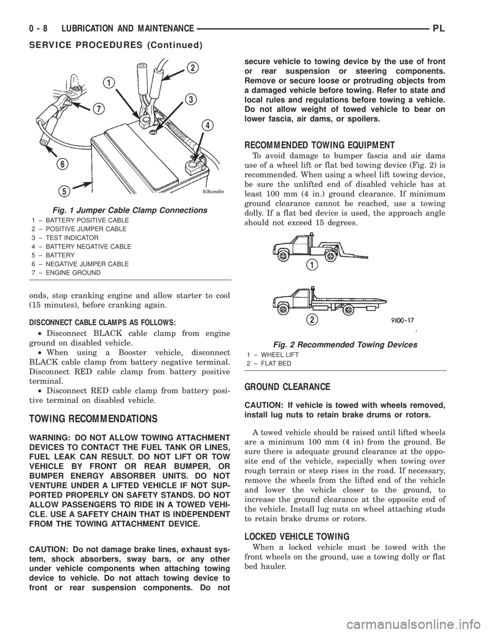
DISCONNECT CABLE CLAMPS AS FOLLOWS:
²Disconnect BLACK cable clamp from engine
ground on disabled vehicle.
²When using a Booster vehicle, disconnect
BLACK cable clamp from battery negative terminal.
Disconnect RED cable clamp from battery positive
terminal.
²Disconnect RED cable clamp from battery posi-
tive terminal on disabled vehicle.
TOWING RECOMMENDATIONS
WARNING: DO NOT ALLOW TOWING ATTACHMENT
DEVICES TO CONTACT THE FUEL TANK OR LINES,
FUEL LEAK CAN RESULT. DO NOT LIFT OR TOW
VEHICLE BY FRONT OR REAR BUMPER, OR
BUMPER ENERGY ABSORBER UNITS. DO NOT
VENTURE UNDER A LIFTED VEHICLE IF NOT SUP-
PORTED PROPERLY ON SAFETY STANDS. DO NOT
ALLOW PASSENGERS TO RIDE IN A TOWED VEHI-
CLE. USE A SAFETY CHAIN THAT IS INDEPENDENT
FROM THE TOWING ATTACHMENT DEVICE.
CAUTION: Do not damage brake lines, exhaust sys-
tem, shock absorbers, sway bars, or any other
under vehicle components when attaching towing
device to vehicle. Do not attach towing device to
front or rear suspension components. Do notsecure vehicle to towing device by the use of front
or rear suspension or steering components.
Remove or secure loose or protruding objects from
a damaged vehicle before towing. Refer to state and
local rules and regulations before towing a vehicle.
Do not allow weight of towed vehicle to bear on
lower fascia, air dams, or spoilers.
RECOMMENDED TOWING EQUIPMENT
To avoid damage to bumper fascia and air dams
use of a wheel lift or flat bed towing device (Fig. 2) is
recommended. When using a wheel lift towing device,
be sure the unlifted end of disabled vehicle has at
least 100 mm (4 in.) ground clearance. If minimum
ground clearance cannot be reached, use a towing
dolly. If a flat bed device is used, the approach angle
should not exceed 15 degrees.
GROUND CLEARANCE
CAUTION: If vehicle is towed with wheels removed,
install lug nuts to retain brake drums or rotors.
A towed vehicle should be raised until lifted wheels
are a minimum 100 mm (4 in) from the ground. Be
sure there is adequate ground clearance at the oppo-
site end of the vehicle, especially when towing over
rough terrain or steep rises in the road. If necessary,
remove the wheels from the lifted end of the vehicle
and lower the vehicle closer to the ground, to
increase the ground clearance at the opposite end of
the vehicle. Install lug nuts on wheel attaching studs
to retain brake drums or rotors.
LOCKED VEHICLE TOWING
When a locked vehicle must be towed with the
front wheels on the ground, use a towing dolly or flat
bed hauler.
Fig. 1 Jumper Cable Clamp Connections
1 ± BATTERY POSITIVE CABLE
2 ± POSITIVE JUMPER CABLE
3 ± TEST INDICATOR
4 ± BATTERY NEGATIVE CABLE
5 ± BATTERY
6 ± NEGATIVE JUMPER CABLE
7 ± ENGINE GROUND
Fig. 2 Recommended Towing Devices
1 ± WHEEL LIFT
2 ± FLAT BED
0 - 8 LUBRICATION AND MAINTENANCEPL
SERVICE PROCEDURES (Continued)
Page 24 of 1285
STEERING KNUCKLE
The front suspension steering knuckle is not a
repairable component of the front suspension. It
must be replaced if found to be damaged in any way.
If it is determined that the steering knuckle is bent
when servicing the vehicle, no attempt is to be made
to straighten the steering knuckle.
WHEEL BEARING AND HUB
The wheel bearing is designed for the life of the
vehicle and requires no type of periodic maintenance.
The following procedure may be used for diagnosing
the condition of the wheel bearing and hub.
With the wheel, disc brake caliper, and brake rotor
removed, rotate the wheel hub. Any roughness or
resistance to rotation may indicate dirt intrusion or a
failed hub bearing. If the bearing exhibits any of
these conditions during diagnosis, the hub bearing
will require replacement. The bearing is not service-
able.Damaged bearing seals and the resulting excessive
grease loss may also require bearing replacement.
Moderate grease weapage from the bearing is consid-
ered normal and should not require replacement of
the wheel bearing.
To diagnose a bent hub, refer to BRAKE ROTOR in
the DIAGNOSIS AND TESTING section in the
BRAKES service manual group for the procedure on
measuring hub runout.
LOWER CONTROL ARM
Inspect the lower control arm for signs of damage
from contact with the ground or road debris. If the
lower control arm shows any sign of damage, look for
distortion. Do not attempt to repair or straighten a
broken or bent lower control arm. If damaged, the
lower control arm stamping is serviced only as a
complete component.
The serviceable components of the lower control
arm are: the ball joint, the ball joint grease seal and
the lower control arm rear isolator bushing.
Inspect both lower control arm isolator bushings
for severe deterioration and replace as required.
Inspect the ball joint per the inspection procedure in
this section of the service manual and replace as
required. Refer to BALL JOINT in this section of this
service manual group.
BALL JOINT
With the weight of the vehicle resting on the road
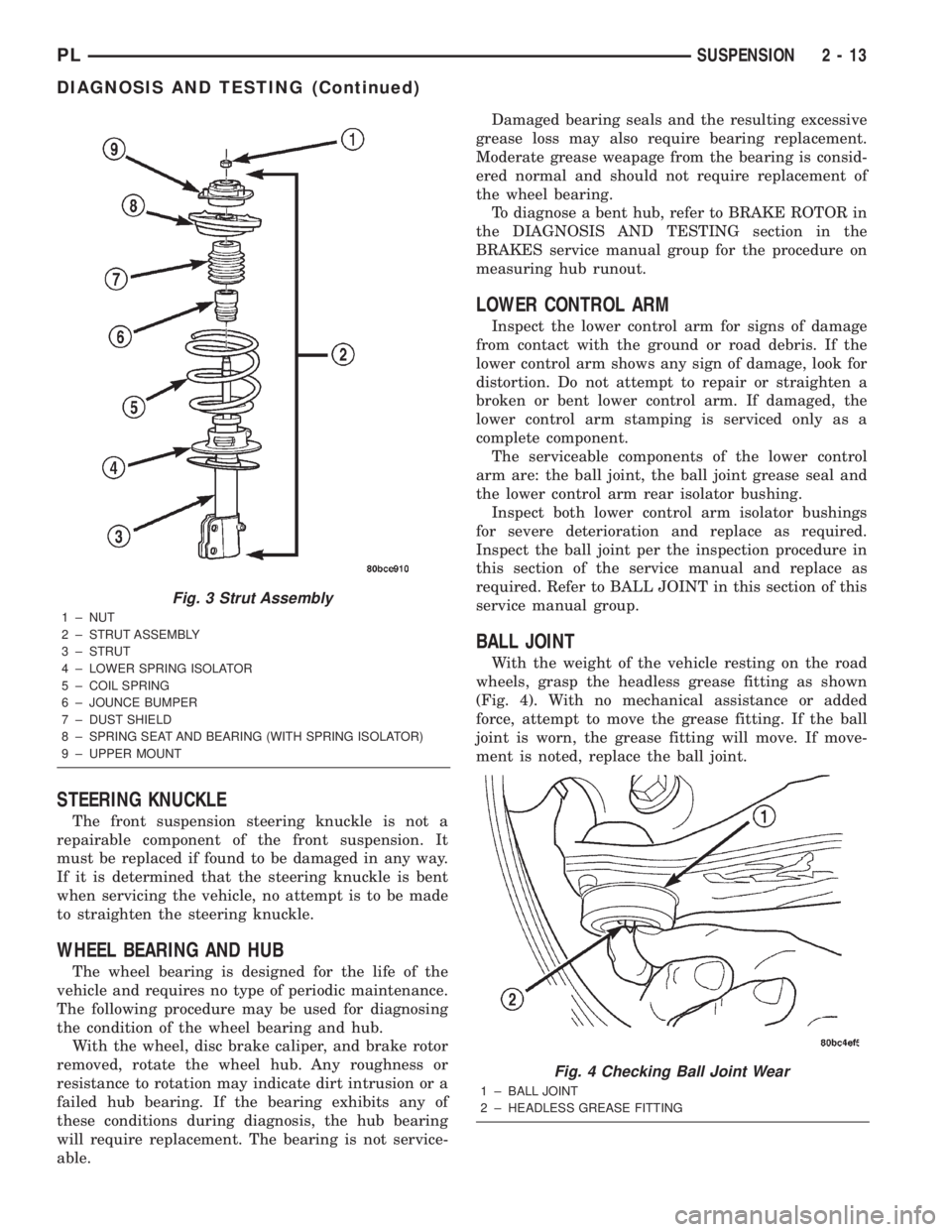
wheels, grasp the headless grease fitting as shown
(Fig. 4). With no mechanical assistance or added
force, attempt to move the grease fitting. If the ball
joint is worn, the grease fitting will move. If move-
ment is noted, replace the ball joint.
Fig. 3 Strut Assembly
1 ± NUT
2 ± STRUT ASSEMBLY
3 ± STRUT
4 ± LOWER SPRING ISOLATOR
5 ± COIL SPRING
6 ± JOUNCE BUMPER
7 ± DUST SHIELD
8 ± SPRING SEAT AND BEARING (WITH SPRING ISOLATOR)
9 ± UPPER MOUNT
Fig. 4 Checking Ball Joint Wear
1 ± BALL JOINT
2 ± HEADLESS GREASE FITTING
PLSUSPENSION 2 - 13
DIAGNOSIS AND TESTING (Continued)
Page 27 of 1285
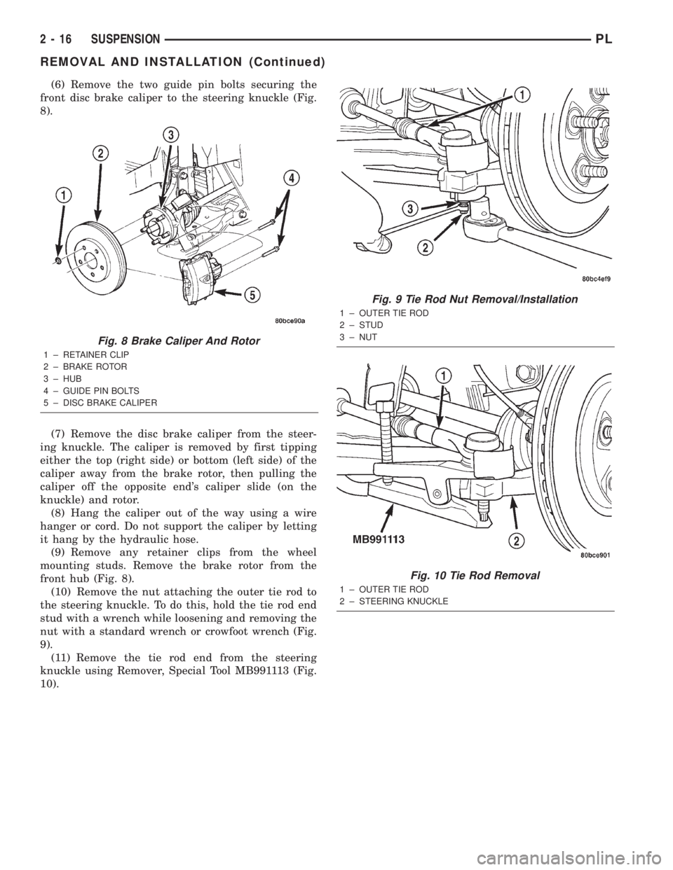
(6) Remove the two guide pin bolts securing the
front disc brake caliper to the steering knuckle (Fig.
8).
(7) Remove the disc brake caliper from the steer-
ing knuckle. The caliper is removed by first tipping
either the top (right side) or bottom (left side) of the
caliper away from the brake rotor, then pulling the
caliper off the opposite end's caliper slide (on the
knuckle) and rotor.
(8) Hang the caliper out of the way using a wire
hanger or cord. Do not support the caliper by letting
it hang by the hydraulic hose.
(9) Remove any retainer clips from the wheel
mounting studs. Remove the brake rotor from the
front hub (Fig. 8).
(10) Remove the nut attaching the outer tie rod to
the steering knuckle. To do this, hold the tie rod end
stud with a wrench while loosening and removing the
nut with a standard wrench or crowfoot wrench (Fig.
9).
(11) Remove the tie rod end from the steering
knuckle using Remover, Special Tool MB991113 (Fig.
10).
Fig. 8 Brake Caliper And Rotor
1 ± RETAINER CLIP
2 ± BRAKE ROTOR
3 ± HUB
4 ± GUIDE PIN BOLTS
5 ± DISC BRAKE CALIPER
Fig. 9 Tie Rod Nut Removal/Installation
1 ± OUTER TIE ROD
2 ± STUD
3 ± NUT
Fig. 10 Tie Rod Removal
1 ± OUTER TIE ROD
2 ± STEERING KNUCKLE
2 - 16 SUSPENSIONPL
REMOVAL AND INSTALLATION (Continued)
Page 29 of 1285
once installed. Install the nuts. Holding the bolts in
place tighten the nuts to a torque of 53 N´m (40 ft.
lbs.) plus an additional 90É turn after the specified
torque is met.
(6) Place the tie rod heat shield on the steering
knuckle arm so that the shield is positioned straight
away from the steering gear and tie rod end once
installed. Algn the hole in the shield with the hole in
the steering knucle arm.
(7) Install the outer tie rod ball stud into the hole
in the steering knuckle arm. Start the tie rod attach-
ing nut onto the stud. Hold the tie rod end stud with
a wrench while tightening the nut with a standard
wrench or crowfoot wrench (Fig. 9). To fully tighten
the nut to specifications, use a crowfoot wrench on a
torque wrench to turn the nut, and a wrench on the
stud. Tighten the nut to a torque of 55 N´m (40 ft.
lbs.).
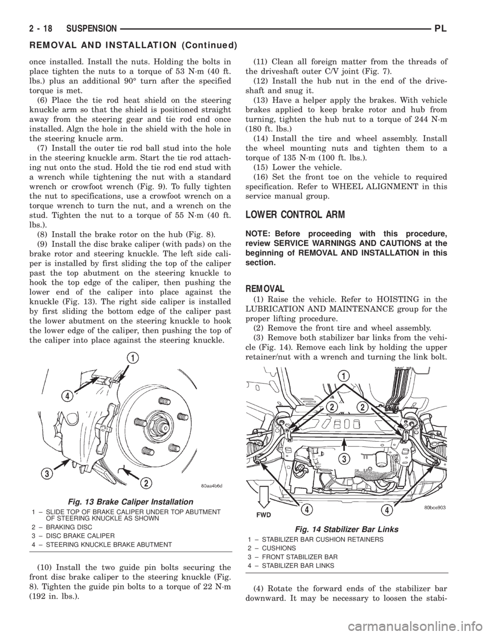
(8) Install the brake rotor on the hub (Fig. 8).
(9) Install the disc brake caliper (with pads) on the
brake rotor and steering knuckle. The left side cali-
per is installed by first sliding the top of the caliper
past the top abutment on the steering knuckle to
hook the top edge of the caliper, then pushing the
lower end of the caliper into place against the
knuckle (Fig. 13). The right side caliper is installed
by first sliding the bottom edge of the caliper past
the lower abutment on the steering knuckle to hook
the lower edge of the caliper, then pushing the top of
the caliper into place against the steering knuckle.
(10) Install the two guide pin bolts securing the
front disc brake caliper to the steering knuckle (Fig.
8). Tighten the guide pin bolts to a torque of 22 N´m
(192 in. lbs.).(11) Clean all foreign matter from the threads of
the driveshaft outer C/V joint (Fig. 7).
(12) Install the hub nut in the end of the drive-
shaft and snug it.
(13) Have a helper apply the brakes. With vehicle
brakes applied to keep brake rotor and hub from
turning, tighten the hub nut to a torque of 244 N´m
(180 ft. lbs.)
(14) Install the tire and wheel assembly. Install
the wheel mounting nuts and tighten them to a
torque of 135 N´m (100 ft. lbs.).
(15) Lower the vehicle.
(16) Set the front toe on the vehicle to required
specification. Refer to WHEEL ALIGNMENT in this
service manual group.
LOWER CONTROL ARM
NOTE: Before proceeding with this procedure,
review SERVICE WARNINGS AND CAUTIONS at the
beginning of REMOVAL AND INSTALLATION in this
section.
REMOVAL
(1) Raise the vehicle. Refer to HOISTING in the
LUBRICATION AND MAINTENANCE group for the
proper lifting procedure.
(2) Remove the front tire and wheel assembly.
(3) Remove both stabilizer bar links from the vehi-
cle (Fig. 14). Remove each link by holding the upper
retainer/nut with a wrench and turning the link bolt.
(4) Rotate the forward ends of the stabilizer bar
downward. It may be necessary to loosen the stabi-
Fig. 13 Brake Caliper Installation
1 ± SLIDE TOP OF BRAKE CALIPER UNDER TOP ABUTMENT
OF STEERING KNUCKLE AS SHOWN
2 ± BRAKING DISC
3 ± DISC BRAKE CALIPER
4 ± STEERING KNUCKLE BRAKE ABUTMENT
Fig. 14 Stabilizer Bar Links
1 ± STABILIZER BAR CUSHION RETAINERS
2 ± CUSHIONS
3 ± FRONT STABILIZER BAR
4 ± STABILIZER BAR LINKS
2 - 18 SUSPENSIONPL
REMOVAL AND INSTALLATION (Continued)
Page 32 of 1285
(4) Lower the vehicle.
NOTE: It may be necessary to put the vehicle on a
platform hoist or alignment rack to gain access to
the stabilizer bar mounting bolts with the vehicle at
curb height.
(5) Tighten each stabilizer bar link by holding the
upper retainer/nut with a wrench and turning the
link bolt. Tighten each link bolt to a torque of 23
N´m (200 in. lbs.).
(6) Tighten the stabilizer bar cushion retainer
bolts to a torque of 28 N´m (250 in. lbs.).
WHEEL MOUNTING STUD (FRONT)
NOTE: Before proceeding with this procedure,
review SERVICE WARNINGS AND CAUTIONS at the
beginning of REMOVAL AND INSTALLATION in this
section.
Use the following procedure to remove and install
one of five studs on one wheel hub.
REMOVAL
(1) Raise the vehicle. Refer to HOISTING in the
LUBRICATION AND MAINTENANCE group for the
proper lifting procedure.
(2) Remove the front tire and wheel assembly.
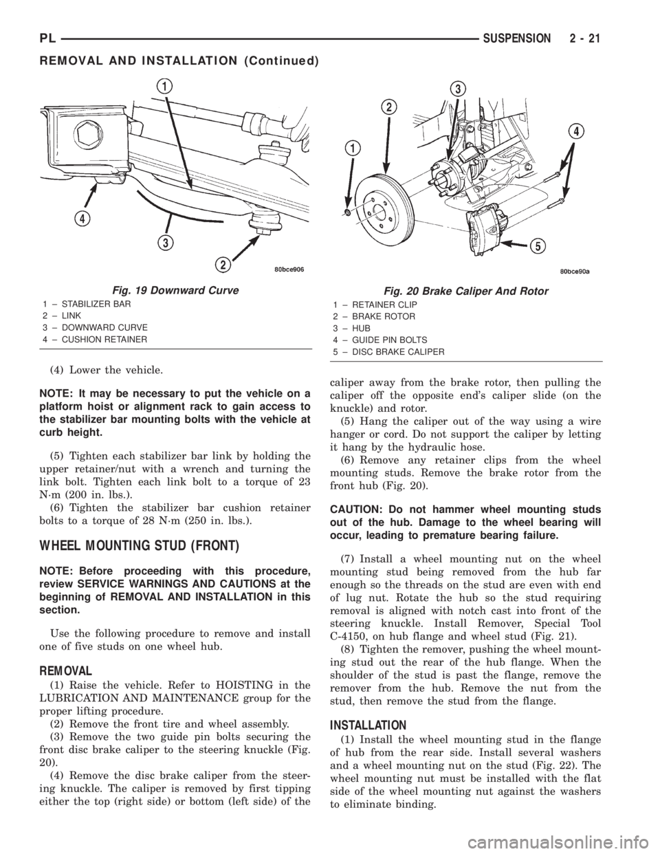
(3) Remove the two guide pin bolts securing the
front disc brake caliper to the steering knuckle (Fig.
20).
(4) Remove the disc brake caliper from the steer-
ing knuckle. The caliper is removed by first tipping
either the top (right side) or bottom (left side) of thecaliper away from the brake rotor, then pulling the
caliper off the opposite end's caliper slide (on the
knuckle) and rotor.
(5) Hang the caliper out of the way using a wire
hanger or cord. Do not support the caliper by letting
it hang by the hydraulic hose.
(6) Remove any retainer clips from the wheel
mounting studs. Remove the brake rotor from the
front hub (Fig. 20).
CAUTION: Do not hammer wheel mounting studs
out of the hub. Damage to the wheel bearing will
occur, leading to premature bearing failure.
(7) Install a wheel mounting nut on the wheel
mounting stud being removed from the hub far
enough so the threads on the stud are even with end
of lug nut. Rotate the hub so the stud requiring
removal is aligned with notch cast into front of the
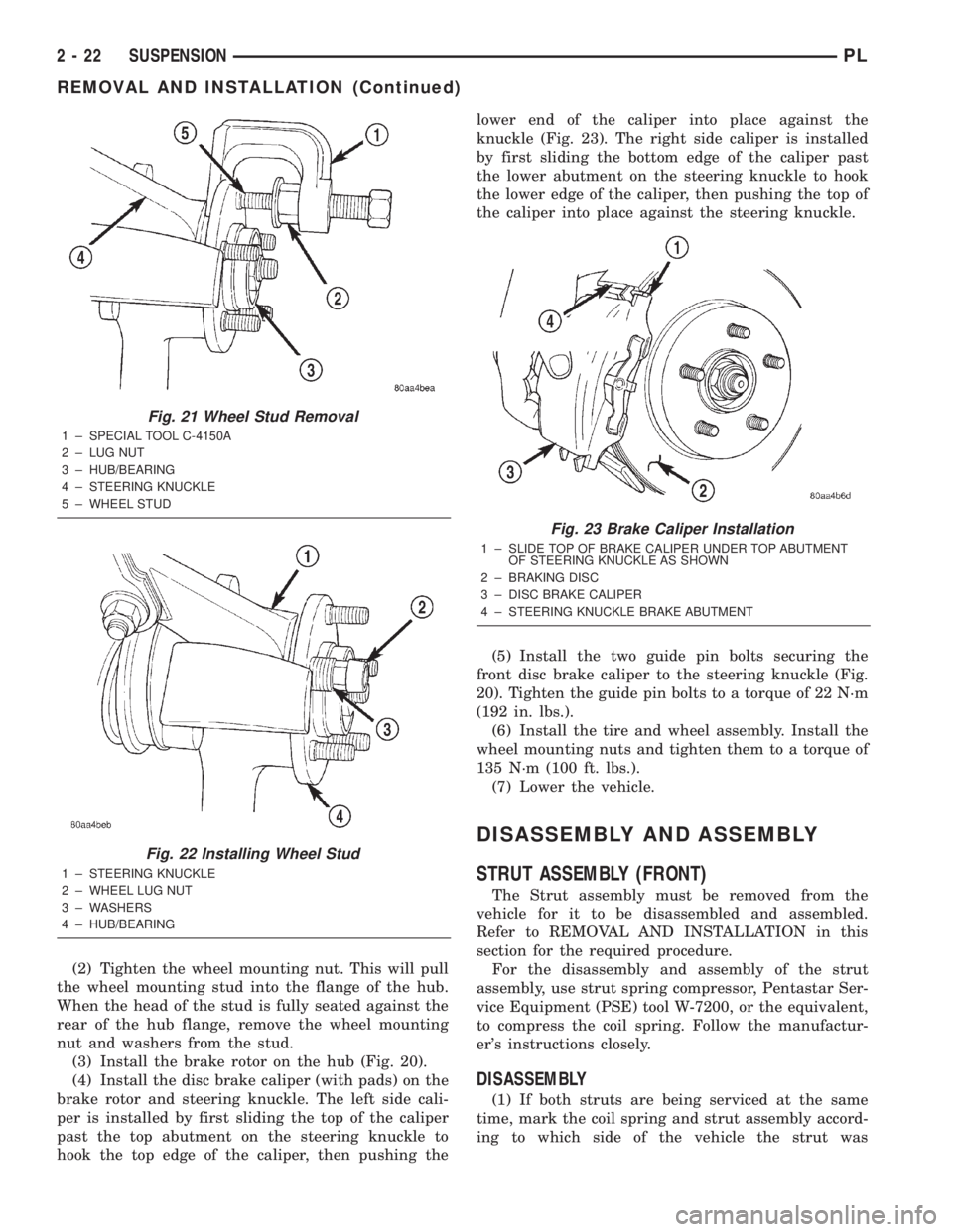
steering knuckle. Install Remover, Special Tool
C-4150, on hub flange and wheel stud (Fig. 21).
(8) Tighten the remover, pushing the wheel mount-
ing stud out the rear of the hub flange. When the
shoulder of the stud is past the flange, remove the
remover from the hub. Remove the nut from the
stud, then remove the stud from the flange.
INSTALLATION
(1) Install the wheel mounting stud in the flange
of hub from the rear side. Install several washers
and a wheel mounting nut on the stud (Fig. 22). The
wheel mounting nut must be installed with the flat
side of the wheel mounting nut against the washers
to eliminate binding.
Fig. 19 Downward Curve
1 ± STABILIZER BAR
2 ± LINK
3 ± DOWNWARD CURVE
4 ± CUSHION RETAINER
Fig. 20 Brake Caliper And Rotor
1 ± RETAINER CLIP
2 ± BRAKE ROTOR
3 ± HUB
4 ± GUIDE PIN BOLTS
5 ± DISC BRAKE CALIPER
PLSUSPENSION 2 - 21
REMOVAL AND INSTALLATION (Continued)
Page 33 of 1285
(2) Tighten the wheel mounting nut. This will pull
the wheel mounting stud into the flange of the hub.
When the head of the stud is fully seated against the
rear of the hub flange, remove the wheel mounting
nut and washers from the stud.
(3) Install the brake rotor on the hub (Fig. 20).
(4) Install the disc brake caliper (with pads) on the
brake rotor and steering knuckle. The left side cali-
per is installed by first sliding the top of the caliper
past the top abutment on the steering knuckle to
hook the top edge of the caliper, then pushing thelower end of the caliper into place against the
knuckle (Fig. 23). The right side caliper is installed
by first sliding the bottom edge of the caliper past
the lower abutment on the steering knuckle to hook
the lower edge of the caliper, then pushing the top of
the caliper into place against the steering knuckle.
(5) Install the two guide pin bolts securing the
front disc brake caliper to the steering knuckle (Fig.
20). Tighten the guide pin bolts to a torque of 22 N´m
(192 in. lbs.).
(6) Install the tire and wheel assembly. Install the
wheel mounting nuts and tighten them to a torque of
135 N´m (100 ft. lbs.).
(7) Lower the vehicle.
DISASSEMBLY AND ASSEMBLY
STRUT ASSEMBLY (FRONT)
The Strut assembly must be removed from the
vehicle for it to be disassembled and assembled.
Refer to REMOVAL AND INSTALLATION in this
section for the required procedure.
For the disassembly and assembly of the strut
assembly, use strut spring compressor, Pentastar Ser-
vice Equipment (PSE) tool W-7200, or the equivalent,
to compress the coil spring. Follow the manufactur-
er's instructions closely.
DISASSEMBLY
(1) If both struts are being serviced at the same
time, mark the coil spring and strut assembly accord-
ing to which side of the vehicle the strut was
Fig. 21 Wheel Stud Removal
1 ± SPECIAL TOOL C-4150A
2 ± LUG NUT
3 ± HUB/BEARING
4 ± STEERING KNUCKLE
5 ± WHEEL STUD
Fig. 22 Installing Wheel Stud
1 ± STEERING KNUCKLE
2 ± WHEEL LUG NUT
3 ± WASHERS
4 ± HUB/BEARING
Fig. 23 Brake Caliper Installation
1 ± SLIDE TOP OF BRAKE CALIPER UNDER TOP ABUTMENT
OF STEERING KNUCKLE AS SHOWN
2 ± BRAKING DISC
3 ± DISC BRAKE CALIPER
4 ± STEERING KNUCKLE BRAKE ABUTMENT
2 - 22 SUSPENSIONPL
REMOVAL AND INSTALLATION (Continued)
Page 50 of 1285
KNUCKLE (REAR)
The rear knuckle is not a repairable component of
the rear suspension. Upon visual inspection, if it is
determined that the knuckle is cracked, bent or bro-
ken, no attempt is to be made to repair or to
straighten the knuckle. The knuckle must be
replaced if found to be damaged in any way.
HUB AND BEARING (REAR)
The hub and bearing is designed for the life of the
vehicle and requires no type of periodic maintenance
(Fig. 1). The following procedure may be used for
diagnosing the condition of the hub and bearing.
With the wheel, disc brake rotor or brake drum
removed, rotate the hub. Any roughness or resistance
to rotation may indicate dirt intrusion or a failed hub
bearing. If the bearing exhibits any of these condi-
tions during diagnosis, the hub and bearing will
require replacement. The bearing is not serviceable
alone.
Damaged bearing seals and the resulting excessive
grease loss may also require hub and bearing
replacement. Moderate grease weapage from thebearing is considered normal and should not require
replacement of the wheel bearing.
To diagnose a bent hub, refer to BRAKE ROTOR in
the DIAGNOSIS AND TESTING section in the
BRAKES service manual group for the procedure on
measuring hub runout.
LATERAL ARMS
Inspect each lateral arm (Fig. 1). Look for signs of
contact with an object that has caused damage to the
lateral arm. If the lateral arm is bent or damaged,
the lateral arm will require replacement. Do not
attempt to repair or straighten a lateral arm.
Inspect the lateral arm isolator bushings and their
sleeves for signs of damage or deterioration. If dam-
age or deterioration is present, replacement of the
entire lateral arm will be required. The isolator
bushings cannot be serviced separately from the lat-
eral arms.
TENSION STRUT
Inspect the tension strut (Fig. 1). Look for signs of
contact with any object that has bent or caused other
damage to the tension strut. If the tension strut is
bent or damaged, the tension strut will require
replacement. Do not attempt to repair or straighten a
tension strut.
Inspect the tension strut front (spool type) bushing,
and rear (bayonet type) bushings and retainers for
signs of deterioration or damage. If the front bushing
is damaged or shows signs of deteriation, the tension
strut must be replaced. The front bushing cannot be
replaced separately. If the rear bushings are deterio-
rated or damaged, or the retainers are damaged,
replacement is necessary. The bushings and retainers
can be replaced separately from the tension strut.
STABILIZER BAR (REAR)
Inspect the stabilizer bar (Fig. 1). Look for damage
or bending. If damage is evident, the bar must be
replaced.
Inspect for broken, cracked or distorted stabilizer
bar cushions and cushion retainers. The horizontal
slit at the front of each cushion is supposed to be
there. If damage is evident, the cushions can be
replaced separately from the stabilizer bar utilizing
the horizontal slit.
Inspect the stabilizer bar links that attach the sta-
bilizer bar to each rear strut. Look for damage or
deterioration of the bushings on the ends of each
link. Inspect the stabilizer bar link to ensure it is not
bent or broken. If any of these conditions are present,
the stabilizer bar link must be replaced. The links
can be replaced separately from the stabilizer bar.
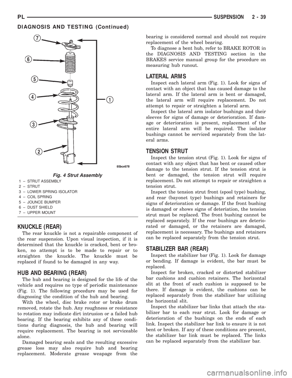
Fig. 4 Strut Assembly
1 ± STRUT ASSEMBLY
2 ± STRUT
3 ± LOWER SPRING ISOLATOR
4 ± COIL SPRING
5 ± JOUNCE BUMPER
6 ± DUST SHIELD
7 ± UPPER MOUNT
PLSUSPENSION 2 - 39
DIAGNOSIS AND TESTING (Continued)
Page 51 of 1285
REMOVAL AND INSTALLATION
SERVICE WARNINGS AND CAUTIONS
WARNING: DO NOT REMOVE THE STRUT SHAFT
NUT WHILE STRUT ASSEMBLY IS INSTALLED IN
VEHICLE, OR BEFORE THE COIL SPRING IS COM-
PRESSED WITH A COMPRESSION TOOL. THE
SPRING IS HELD UNDER HIGH PRESSURE.
CAUTION: Only frame contact or wheel lift hoisting
equipment can be used on vehicles having a fully
independent rear suspension. Vehicles with inde-
pendent rear suspension can not be hoisted using
equipment designed to lift a vehicle by the rear
axle. If this type of hoisting equipment is used dam-
age to rear suspension components will occur.
NOTE: If a rear suspension component becomes
bent, damaged or fails, no attempt should be made
to straighten or repair it. Always replace it with a
new component.
STRUT ASSEMBLY (REAR)
NOTE: Before proceeding with this procedure,
review SERVICE WARNINGS AND CAUTIONS at the
beginning of REMOVAL AND INSTALLATION in this
section.
REMOVAL
(1) Raise the vehicle. Refer to HOISTING in the
LUBRICATION AND MAINTENANCE group for the
proper lifting procedure.
(2) Remove the rear wheel and tire assembly from
the vehicle.
(3) If the vehicle is equipped with rear drum
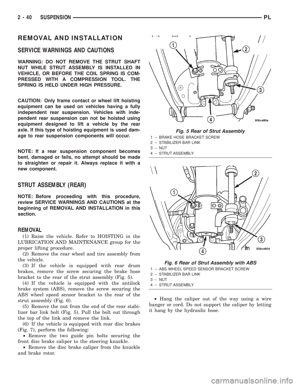
brakes, remove the screw securing the brake hose
bracket to the rear of the strut assembly (Fig. 5).
(4) If the vehicle is equipped with the antilock
brake system (ABS), remove the screw securing the
ABS wheel speed sensor bracket to the rear of the
strut assembly (Fig. 6).
(5) Remove the nut from the end of the rear stabi-
lizer bar link bolt (Fig. 5). Pull the bolt out through
the top of the link and remove the link.
(6) If the vehicle is equipped with rear disc brakes
(Fig. 7), perform the following:
²Remove the two guide pin bolts securing the
front disc brake caliper to the steering knuckle.
²Remove the disc brake caliper from the knuckle
and brake rotor.²Hang the caliper out of the way using a wire
hanger or cord. Do not support the caliper by letting
it hang by the hydraulic hose.
Fig. 5 Rear of Strut Assembly
1 ± BRAKE HOSE BRACKET SCREW
2 ± STABILIZER BAR LINK
3 ± NUT
4 ± STRUT ASSEMBLY
Fig. 6 Rear of Strut Assembly with ABS
1 ± ABS WHEEL SPEED SENSOR BRACKET SCREW
2 ± STABILIZER BAR LINK
3 ± NUT
4 ± STRUT ASSEMBLY
2 - 40 SUSPENSIONPL