2000 DODGE NEON brake rotor
[x] Cancel search: brake rotorPage 100 of 1285
(5) Place the gauge (From A) over the end of the
brake tube. Adjust the tube height in the tool's jaws
until the end of the tube contacts the recessed notch
in the gauge that matches the tubing size. Squeeze
the handles of the flaring tool, locking the tubing in
place. Remove the gauge.
(6) Place the 3/16 inch plug gauge (A) down into
the end of the tube. Tighten the flaring handle, push-
ing the gauge into the tube until the gauge contacts
the vertical posts of the tool.
(7) Release the flaring handle and remove the plug
gauge from the partially flared tube.
(8) Tighten the flaring handle down once more
until the tools flaring tip has firmly seated the tube
to the vertical posts, thus completing the flare.
CAUTION: When inspecting the flare, make sure no
tubing nygal coating has been involved in the flare.
(9) Remove the flared tube from the flaring tool
and inspect the flare to make sure it is uniform.
BRAKE ROTOR MACHINING
NOTE: Refacing the rotor is not required each time
the brake pads are replaced, only when the need is
foreseen.
Any servicing of the rotor requires extreme care to
maintain the rotor within service tolerances to
ensure proper brake action.
If the rotor surface is deeply scored or warped, or
there is a complaint of brake roughness or brake
pedal pulsation, the rotor should be refaced using a
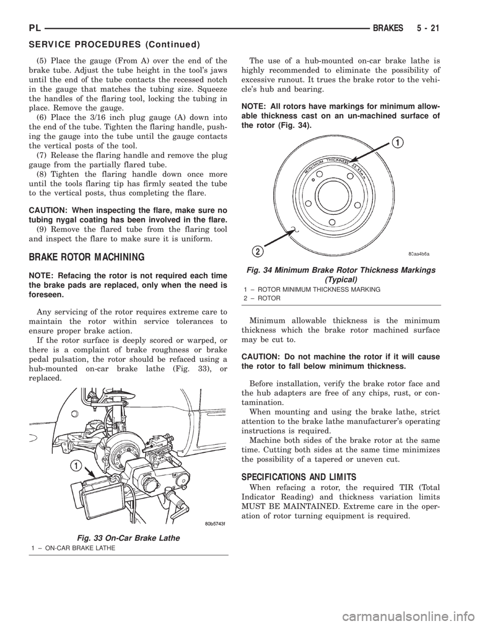
hub-mounted on-car brake lathe (Fig. 33), or
replaced.The use of a hub-mounted on-car brake lathe is
highly recommended to eliminate the possibility of
excessive runout. It trues the brake rotor to the vehi-
cle's hub and bearing.
NOTE: All rotors have markings for minimum allow-
able thickness cast on an un-machined surface of
the rotor (Fig. 34).
Minimum allowable thickness is the minimum
thickness which the brake rotor machined surface
may be cut to.
CAUTION: Do not machine the rotor if it will cause
the rotor to fall below minimum thickness.
Before installation, verify the brake rotor face and
the hub adapters are free of any chips, rust, or con-
tamination.
When mounting and using the brake lathe, strict
attention to the brake lathe manufacturer's operating
instructions is required.
Machine both sides of the brake rotor at the same
time. Cutting both sides at the same time minimizes
the possibility of a tapered or uneven cut.
SPECIFICATIONS AND LIMITS
When refacing a rotor, the required TIR (Total
Indicator Reading) and thickness variation limits
MUST BE MAINTAINED. Extreme care in the oper-
ation of rotor turning equipment is required.
Fig. 33 On-Car Brake Lathe
1 ± ON-CAR BRAKE LATHE
Fig. 34 Minimum Brake Rotor Thickness Markings
(Typical)
1 ± ROTOR MINIMUM THICKNESS MARKING
2 ± ROTOR
PLBRAKES 5 - 21
SERVICE PROCEDURES (Continued)
Page 101 of 1285
BRAKE ROTOR LIMITS
Braking Rotor Rotor ThicknessMinimum
Rotor
ThicknessRotor
Thickness
VariationRotor Run
Out*Rotor Micro
Finish
Front Rotor21.87±22.13 mm
0.861-0.871 in.20.4 mm
0.803 in.0.013 mm
0.0005 in.0.08 mm
0.003 in.15-80 RMS
Rear Rotor8.75±9.25 mm
0.344 -0.364 in.7.25 mm
0.285 in.0.013 mm
0.0005 in.0.08 mm
0.003 in.15-80 RMS
* TIR Total Indicator Reading (Measured On Vehicle)
BRAKE DRUM MACHINING
If a brake drum is deeply scored or warped, it can
be machined on a brake lathe equipped to machine
brake drums. Follow the manufacturers instructions
on the machining procedure.
Measure the brake drum diameter before machin-
ing. If machining the drum will cause the drum to
exceed maximum allowable diameter, do not machine
the brake drum. It needs to be replaced.
CAUTION: Do not machine the brake drum if it will
cause the drum to exceed maximum allowable
diameter.
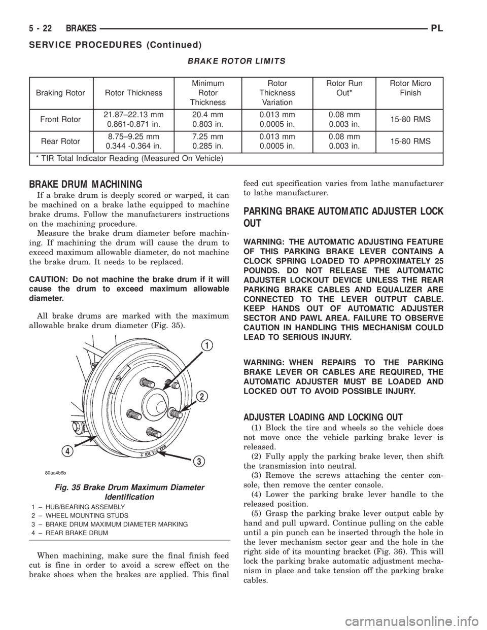
All brake drums are marked with the maximum
allowable brake drum diameter (Fig. 35).
When machining, make sure the final finish feed
cut is fine in order to avoid a screw effect on the
brake shoes when the brakes are applied. This finalfeed cut specification varies from lathe manufacturer
to lathe manufacturer.
PARKING BRAKE AUTOMATIC ADJUSTER LOCK
OUT
WARNING: THE AUTOMATIC ADJUSTING FEATURE
OF THIS PARKING BRAKE LEVER CONTAINS A
CLOCK SPRING LOADED TO APPROXIMATELY 25
POUNDS. DO NOT RELEASE THE AUTOMATIC
ADJUSTER LOCKOUT DEVICE UNLESS THE REAR
PARKING BRAKE CABLES AND EQUALIZER ARE
CONNECTED TO THE LEVER OUTPUT CABLE.
KEEP HANDS OUT OF AUTOMATIC ADJUSTER
SECTOR AND PAWL AREA. FAILURE TO OBSERVE
CAUTION IN HANDLING THIS MECHANISM COULD
LEAD TO SERIOUS INJURY.
WARNING: WHEN REPAIRS TO THE PARKING
BRAKE LEVER OR CABLES ARE REQUIRED, THE
AUTOMATIC ADJUSTER MUST BE LOADED AND
LOCKED OUT TO AVOID POSSIBLE INJURY.
ADJUSTER LOADING AND LOCKING OUT
(1) Block the tire and wheels so the vehicle does
not move once the vehicle parking brake lever is
released.
(2) Fully apply the parking brake lever, then shift
the transmission into neutral.
(3) Remove the screws attaching the center con-
sole, then remove the center console.
(4) Lower the parking brake lever handle to the
released position.
(5) Grasp the parking brake lever output cable by
hand and pull upward. Continue pulling on the cable
until a pin punch can be inserted through the hole in
the lever mechanism sector gear and the hole in the
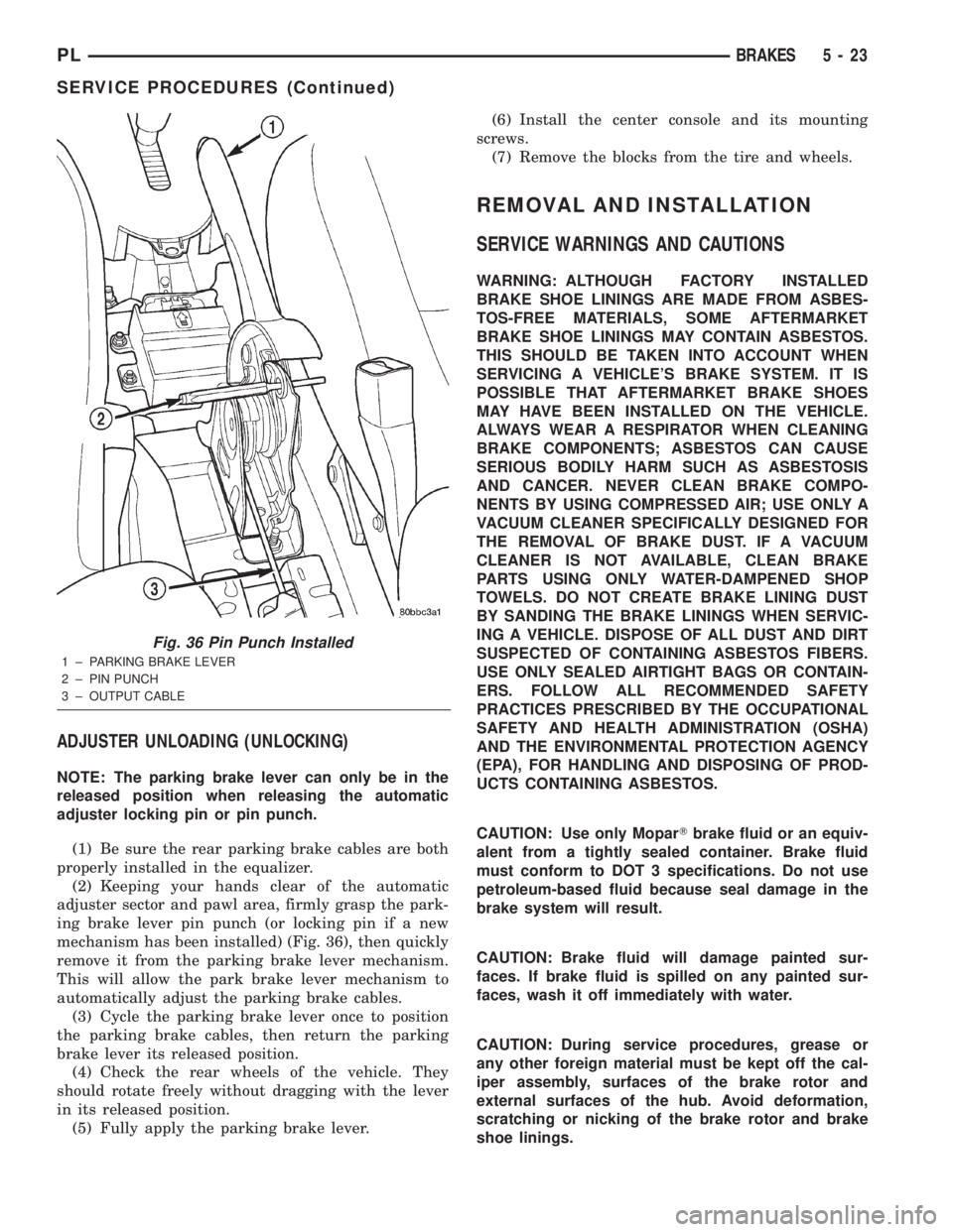
right side of its mounting bracket (Fig. 36). This will
lock the parking brake automatic adjustment mecha-
nism in place and take tension off the parking brake
cables.
Fig. 35 Brake Drum Maximum Diameter
Identification
1 ± HUB/BEARING ASSEMBLY
2 ± WHEEL MOUNTING STUDS
3 ± BRAKE DRUM MAXIMUM DIAMETER MARKING
4 ± REAR BRAKE DRUM
5 - 22 BRAKESPL
SERVICE PROCEDURES (Continued)
Page 102 of 1285
ADJUSTER UNLOADING (UNLOCKING)
NOTE: The parking brake lever can only be in the
released position when releasing the automatic
adjuster locking pin or pin punch.
(1) Be sure the rear parking brake cables are both
properly installed in the equalizer.
(2) Keeping your hands clear of the automatic
adjuster sector and pawl area, firmly grasp the park-
ing brake lever pin punch (or locking pin if a new
mechanism has been installed) (Fig. 36), then quickly
remove it from the parking brake lever mechanism.
This will allow the park brake lever mechanism to
automatically adjust the parking brake cables.
(3) Cycle the parking brake lever once to position
the parking brake cables, then return the parking
brake lever its released position.
(4) Check the rear wheels of the vehicle. They
should rotate freely without dragging with the lever
in its released position.
(5) Fully apply the parking brake lever.(6) Install the center console and its mounting
screws.
(7) Remove the blocks from the tire and wheels.
REMOVAL AND INSTALLATION
SERVICE WARNINGS AND CAUTIONS
WARNING: ALTHOUGH FACTORY INSTALLED
BRAKE SHOE LININGS ARE MADE FROM ASBES-
TOS-FREE MATERIALS, SOME AFTERMARKET
BRAKE SHOE LININGS MAY CONTAIN ASBESTOS.
THIS SHOULD BE TAKEN INTO ACCOUNT WHEN
SERVICING A VEHICLE'S BRAKE SYSTEM. IT IS
POSSIBLE THAT AFTERMARKET BRAKE SHOES
MAY HAVE BEEN INSTALLED ON THE VEHICLE.
ALWAYS WEAR A RESPIRATOR WHEN CLEANING
BRAKE COMPONENTS; ASBESTOS CAN CAUSE
SERIOUS BODILY HARM SUCH AS ASBESTOSIS
AND CANCER. NEVER CLEAN BRAKE COMPO-
NENTS BY USING COMPRESSED AIR; USE ONLY A
VACUUM CLEANER SPECIFICALLY DESIGNED FOR
THE REMOVAL OF BRAKE DUST. IF A VACUUM
CLEANER IS NOT AVAILABLE, CLEAN BRAKE
PARTS USING ONLY WATER-DAMPENED SHOP
TOWELS. DO NOT CREATE BRAKE LINING DUST
BY SANDING THE BRAKE LININGS WHEN SERVIC-
ING A VEHICLE. DISPOSE OF ALL DUST AND DIRT
SUSPECTED OF CONTAINING ASBESTOS FIBERS.
USE ONLY SEALED AIRTIGHT BAGS OR CONTAIN-
ERS. FOLLOW ALL RECOMMENDED SAFETY
PRACTICES PRESCRIBED BY THE OCCUPATIONAL
SAFETY AND HEALTH ADMINISTRATION (OSHA)
AND THE ENVIRONMENTAL PROTECTION AGENCY
(EPA), FOR HANDLING AND DISPOSING OF PROD-
UCTS CONTAINING ASBESTOS.
CAUTION: Use only MoparTbrake fluid or an equiv-
alent from a tightly sealed container. Brake fluid
must conform to DOT 3 specifications. Do not use
petroleum-based fluid because seal damage in the
brake system will result.
CAUTION: Brake fluid will damage painted sur-
faces. If brake fluid is spilled on any painted sur-
faces, wash it off immediately with water.
CAUTION: During service procedures, grease or
any other foreign material must be kept off the cal-
iper assembly, surfaces of the brake rotor and
external surfaces of the hub. Avoid deformation,
scratching or nicking of the brake rotor and brake
shoe linings.
Fig. 36 Pin Punch Installed
1 ± PARKING BRAKE LEVER
2 ± PIN PUNCH
3 ± OUTPUT CABLE
PLBRAKES 5 - 23
SERVICE PROCEDURES (Continued)
Page 113 of 1285
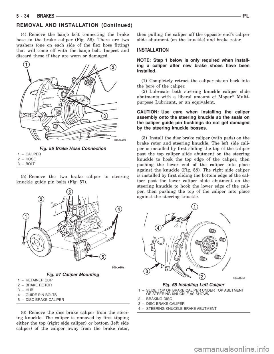
(4) Remove the banjo bolt connecting the brake
hose to the brake caliper (Fig. 56). There are two
washers (one on each side of the flex hose fitting)
that will come off with the banjo bolt. Inspect and
discard these if they are worn or damaged.
(5) Remove the two brake caliper to steering
knuckle guide pin bolts (Fig. 57).
(6) Remove the disc brake caliper from the steer-
ing knuckle. The caliper is removed by first tipping
either the top (right side caliper) or bottom (left side
caliper) of the caliper away from the brake rotor,then pulling the caliper off the opposite end's caliper
slide abutment (on the knuckle) and brake rotor.
INSTALLATION
NOTE: Step 1 below is only required when install-
ing a caliper after new brake shoes have been
installed.
(1) Completely retract the caliper piston back into
the bore of the caliper.
(2) Lubricate both steering knuckle caliper slide
abutments with a liberal amount of MopartMulti-
purpose Lubricant, or an equivalent.
CAUTION: Use care when installing the caliper
assembly onto the steering knuckle so the seals on
the caliper guide pin bushings do not get damaged
by the steering knuckle bosses.
(3) Install the disc brake caliper (with pads) on the
brake rotor and steering knuckle. The left side cali-
per is installed by first sliding the top of the caliper
past the top caliper slide abutment on the steering
knuckle to hook the top edge of the caliper, then
pushing the lower end of the caliper into place
against the knuckle (Fig. 58). The right side caliper
is installed by first sliding the bottom edge of the cal-
iper past the lower caliper slide abutment on the
steering knuckle to hook the lower edge of the cali-
per, then pushing the top of the caliper into place
against the steering knuckle.
Fig. 56 Brake Hose Connection
1 ± CALIPER
2 ± HOSE
3 ± BOLT
Fig. 57 Caliper Mounting
1 ± RETAINER CLIP
2 ± BRAKE ROTOR
3 ± HUB
4 ± GUIDE PIN BOLTS
5 ± DISC BRAKE CALIPER
Fig. 58 Installing Left Caliper
1 ± SLIDE TOP OF BRAKE CALIPER UNDER TOP ABUTMENT
OF STEERING KNUCKLE AS SHOWN
2 ± BRAKING DISC
3 ± DISC BRAKE CALIPER
4 ± STEERING KNUCKLE BRAKE ABUTMENT
5 - 34 BRAKESPL
REMOVAL AND INSTALLATION (Continued)
Page 114 of 1285
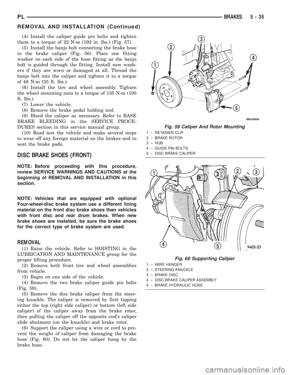
(4) Install the caliper guide pin bolts and tighten
them to a torque of 22 N´m (192 in. lbs.) (Fig. 57).
(5) Install the banjo bolt connecting the brake hose
to the brake caliper (Fig. 56). Place one fitting
washer on each side of the hose fitting as the banjo
bolt is guided through the fitting. Install new wash-
ers if they are worn or damaged at all. Thread the
banjo bolt into the caliper and tighten it to a torque
of 48 N´m (35 ft. lbs.).
(6) Install the tire and wheel assembly. Tighten
the wheel mounting nuts to a torque of 135 N´m (100
ft. lbs.).
(7) Lower the vehicle.
(8) Remove the brake pedal holding tool.
(9) Bleed the caliper as necessary. Refer to BASE
BRAKE BLEEDING in the SERVICE PROCE-
DURES section in this service manual group.
(10) Road test the vehicle and make several stops
to wear off any foreign material on the brakes and to
seat the brake pads.
DISC BRAKE SHOES (FRONT)
NOTE: Before proceeding with this procedure,
review SERVICE WARNINGS AND CAUTIONS at the
beginning of REMOVAL AND INSTALLATION in this
section.
NOTE: Vehicles that are equipped with optional
Four-wheel-disc brake system use a different lining
material on the front disc brake shoes than vehicles
with front disc and rear drum brakes. When new
brake shoes are installed, be sure the brake shoes
for the correct type of brake system are used.
REMOVAL
(1) Raise the vehicle. Refer to HOISTING in the
LUBRICATION AND MAINTENANCE group for the
proper lifting procedure.
(2) Remove both front tire and wheel assemblies
from vehicle.
(3) Begin on one side of the vehicle.
(4) Remove the two brake caliper guide pin bolts
(Fig. 59).
(5) Remove the disc brake caliper from the steer-
ing knuckle. The caliper is removed by first tipping
either the top (right side caliper) or bottom (left side
caliper) of the caliper away from the brake rotor,
then pulling the caliper off the opposite end's caliper
slide abutment (on the knuckle) and brake rotor.
(6) Support the caliper using a wire or cord to pre-
vent the weight of caliper from damaging the brake
hose (Fig. 60). Do not let the caliper hang by the
brake hose.
Fig. 59 Caliper And Rotor Mounting
1 ± RETAINER CLIP
2 ± BRAKE ROTOR
3 ± HUB
4 ± GUIDE PIN BOLTS
5 ± DISC BRAKE CALIPER
Fig. 60 Supporting Caliper
1 ± WIRE HANGER
2 ± STEERING KNUCKLE
3 ± BRAKE DISC
4 ± DISC BRAKE CALIPER ASSEMBLY
5 ± BRAKE HYDRAULIC HOSE
PLBRAKES 5 - 35
REMOVAL AND INSTALLATION (Continued)
Page 115 of 1285
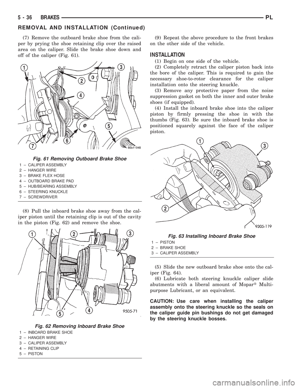
(7) Remove the outboard brake shoe from the cali-
per by prying the shoe retaining clip over the raised
area on the caliper. Slide the brake shoe down and
off of the caliper (Fig. 61).
(8) Pull the inboard brake shoe away from the cal-
iper piston until the retaining clip is out of the cavity
in the piston (Fig. 62) and remove the shoe.(9) Repeat the above procedure to the front brakes
on the other side of the vehicle.
INSTALLATION
(1) Begin on one side of the vehicle.
(2) Completely retract the caliper piston back into
the bore of the caliper. This is required to gain the
necessary shoe-to-rotor clearance for the caliper
installation onto the steering knuckle.
(3) Remove any protective paper from the noise
suppression gasket on both the inner and outer brake
shoes (if equipped).
(4) Install the inboard brake shoe into the caliper
piston by firmly pressing the shoe in with the
thumbs (Fig. 63). Be sure the inboard brake shoe is
positioned squarely against the face of the caliper
piston.
(5) Slide the new outboard brake shoe onto the cal-
iper (Fig. 64).
(6) Lubricate both steering knuckle caliper slide
abutments with a liberal amount of MopartMulti-
purpose Lubricant, or an equivalent.
CAUTION: Use care when installing the caliper
assembly onto the steering knuckle so the seals on
the caliper guide pin bushings do not get damaged
by the steering knuckle bosses.
Fig. 61 Removing Outboard Brake Shoe
1 ± CALIPER ASSEMBLY
2 ± HANGER WIRE
3 ± BRAKE FLEX HOSE
4 ± OUTBOARD BRAKE PAD
5 ± HUB/BEARING ASSEMBLY
6 ± STEERING KNUCKLE
7 ± SCREWDRIVER
Fig. 62 Removing Inboard Brake Shoe
1 ± INBOARD BRAKE SHOE
2 ± HANGER WIRE
3 ± CALIPER ASSEMBLY
4 ± RETAINING CLIP
5 ± PISTON
Fig. 63 Installing Inboard Brake Shoe
1 ± PISTON
2 ± BRAKE SHOE
3 ± CALIPER ASSEMBLY
5 - 36 BRAKESPL
REMOVAL AND INSTALLATION (Continued)
Page 116 of 1285
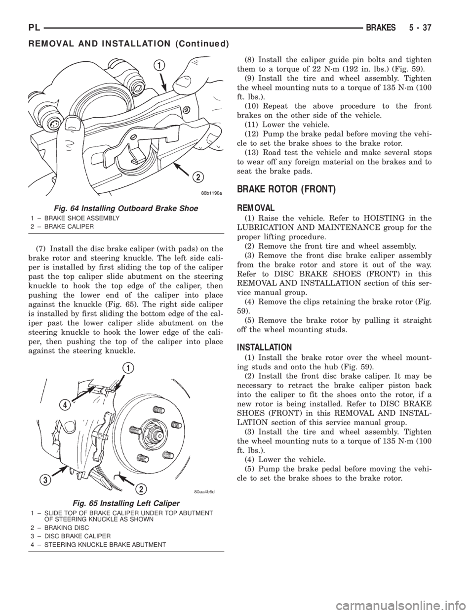
(7) Install the disc brake caliper (with pads) on the
brake rotor and steering knuckle. The left side cali-
per is installed by first sliding the top of the caliper
past the top caliper slide abutment on the steering
knuckle to hook the top edge of the caliper, then
pushing the lower end of the caliper into place
against the knuckle (Fig. 65). The right side caliper
is installed by first sliding the bottom edge of the cal-
iper past the lower caliper slide abutment on the
steering knuckle to hook the lower edge of the cali-
per, then pushing the top of the caliper into place
against the steering knuckle.(8) Install the caliper guide pin bolts and tighten
them to a torque of 22 N´m (192 in. lbs.) (Fig. 59).
(9) Install the tire and wheel assembly. Tighten
the wheel mounting nuts to a torque of 135 N´m (100
ft. lbs.).
(10) Repeat the above procedure to the front
brakes on the other side of the vehicle.
(11) Lower the vehicle.
(12) Pump the brake pedal before moving the vehi-
cle to set the brake shoes to the brake rotor.
(13) Road test the vehicle and make several stops
to wear off any foreign material on the brakes and to
seat the brake pads.
BRAKE ROTOR (FRONT)
REMOVAL
(1) Raise the vehicle. Refer to HOISTING in the
LUBRICATION AND MAINTENANCE group for the
proper lifting procedure.
(2) Remove the front tire and wheel assembly.
(3) Remove the front disc brake caliper assembly
from the brake rotor and store it out of the way.
Refer to DISC BRAKE SHOES (FRONT) in this
REMOVAL AND INSTALLATION section of this ser-
vice manual group.
(4) Remove the clips retaining the brake rotor (Fig.
59).
(5) Remove the brake rotor by pulling it straight
off the wheel mounting studs.
INSTALLATION
(1) Install the brake rotor over the wheel mount-
ing studs and onto the hub (Fig. 59).
(2) Install the front disc brake caliper. It may be
necessary to retract the brake caliper piston back
into the caliper to fit the shoes onto the rotor, if a
new rotor is being installed. Refer to DISC BRAKE
SHOES (FRONT) in this REMOVAL AND INSTAL-
LATION section of this service manual group.
(3) Install the tire and wheel assembly. Tighten
the wheel mounting nuts to a torque of 135 N´m (100
ft. lbs.).
(4) Lower the vehicle.
(5) Pump the brake pedal before moving the vehi-
cle to set the brake shoes to the brake rotor.
Fig. 64 Installing Outboard Brake Shoe
1 ± BRAKE SHOE ASSEMBLY
2 ± BRAKE CALIPER
Fig. 65 Installing Left Caliper
1 ± SLIDE TOP OF BRAKE CALIPER UNDER TOP ABUTMENT
OF STEERING KNUCKLE AS SHOWN
2 ± BRAKING DISC
3 ± DISC BRAKE CALIPER
4 ± STEERING KNUCKLE BRAKE ABUTMENT
PLBRAKES 5 - 37
REMOVAL AND INSTALLATION (Continued)
Page 117 of 1285
DISC BRAKE CALIPER (REAR)
REMOVAL
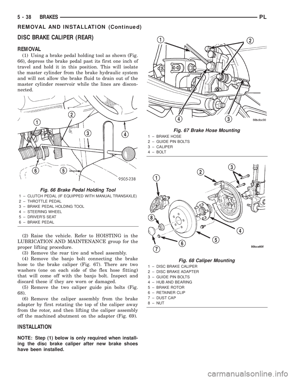
(1) Using a brake pedal holding tool as shown (Fig.
66), depress the brake pedal past its first one inch of
travel and hold it in this position. This will isolate
the master cylinder from the brake hydraulic system
and will not allow the brake fluid to drain out of the
master cylinder reservoir while the lines are discon-
nected.
(2) Raise the vehicle. Refer to HOISTING in the
LUBRICATION AND MAINTENANCE group for the
proper lifting procedure.
(3) Remove the rear tire and wheel assembly.
(4) Remove the banjo bolt connecting the brake
hose to the brake caliper (Fig. 67). There are two
washers (one on each side of the flex hose fitting)
that will come off with the banjo bolt. Inspect and
discard these if they are worn or damaged.
(5) Remove the two caliper guide pin bolts (Fig.
68).
(6) Remove the caliper assembly from the brake
adapter by first rotating the top of the caliper away
from the rotor, and then lifting the caliper assembly
off the machined abutment on the adapter (Fig. 69).
INSTALLATION
NOTE: Step (1) below is only required when install-
ing the disc brake caliper after new brake shoes
have been installed.
Fig. 66 Brake Pedal Holding Tool
1 ± CLUTCH PEDAL (IF EQUIPPED WITH MANUAL TRANSAXLE)
2 ± THROTTLE PEDAL
3 ± BRAKE PEDAL HOLDING TOOL
4 ± STEERING WHEEL
5 ± DRIVER'S SEAT
6 ± BRAKE PEDAL
Fig. 67 Brake Hose Mounting
1 ± BRAKE HOSE
2 ± GUIDE PIN BOLTS
3 ± CALIPER
4 ± BOLT
Fig. 68 Caliper Mounting
1 ± DISC BRAKE CALIPER
2 ± DISC BRAKE ADAPTER
3 ± GUIDE PIN BOLTS
4 ± HUB AND BEARING
5 ± BRAKE ROTOR
6 ± RETAINER CLIP
7 ± DUST CAP
8 ± NUT
5 - 38 BRAKESPL
REMOVAL AND INSTALLATION (Continued)