2000 DODGE NEON brake rotor
[x] Cancel search: brake rotorPage 52 of 1285
CAUTION: The strut-to-knuckle attaching bolts are
serrated and must not be turned during removal.
Hold the bolts stationary in the steering knuckle
while removing the nuts, then tap the bolts out
using a pin punch.
(7) Remove the two nuts and bolts attaching the
strut to the rear knuckle (Fig. 1).
(8) Lower the vehicle just enough to access the
luggage compartment without letting the tires touch
the floor. Access to rear upper strut mount attaching
bolts is through the luggage compartment.
(9) Open the deck lid.
(10) If equipped, remove the carpet from the top of
the strut tower.
(11) Loosen, but do not completely remove the 3
nuts securing the strut assembly to the strut tower
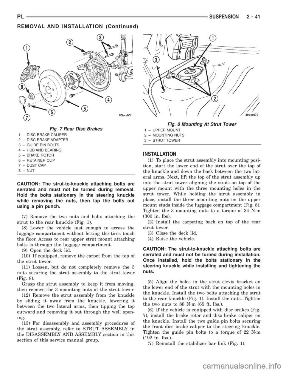
(Fig. 8).
Grasp the strut assembly to keep it from moving,
then remove the 3 mounting nuts at the strut tower.
(12) Remove the strut assembly from the knuckle
by sliding it away from the knuckle, lowering it
between the two lateral arms, then tipping the top
outward and removing it out through the well open-
ing.
(13) For disassembly and assembly procedures of
the strut assembly, refer to STRUT ASSEMBLY in
the DISASSEMBLY AND ASSEMBLY section in this
section of this service manual group.
INSTALLATION
(1) To place the strut assembly into mounting posi-
tion, start the lower end of the strut over the top of
the knuckle and down the back between the two lat-
eral arms. Next, lift the top of the strut assembly up
into the strut tower aligning the studs on top of the
upper mount with the three mounting holes in the
strut tower. While holding the strut assembly in
place, install the three mounting nuts on the upper
mount studs inside the luggage compartment (Fig. 8).
Tighten the 3 mounting nuts to a torque of 34 N´m
(300 in. lbs).
(2) Install the carpeting back on top of the rear
strut tower.
(3) Close the deck lid.
(4) Raise the vehicle.
CAUTION: The strut-to-knuckle attaching bolts are
serrated and must not be turned during installation.
Once installed, hold the bolts stationary in the
steering knuckle while installing and tightening the
nuts.
(5) Align the holes in the strut clevis bracket on
the lower end of the strut with the mounting holes in
the knuckle. Install the two bolts attaching the strut
to the rear knuckle (Fig. 1). Install the nuts. Tighten
the two nuts to 88 N´m (65 ft. lbs.).
(6) If the vehicle is equipped with disc brakes (Fig.
7), install the brake rotor and disc brake caliper on
the knuckle. Install the two guide pin bolts securing
the front disc brake caliper to the steering knuckle.
Tighten the guide pin bolts to a torque of 22 N´m
(192 in. lbs.).
(7) Reinstall the stabilizer bar link (Fig. 1):
Fig. 7 Rear Disc Brakes
1 ± DISC BRAKE CALIPER
2 ± DISC BRAKE ADAPTER
3 ± GUIDE PIN BOLTS
4 ± HUB AND BEARING
5 ± BRAKE ROTOR
6 ± RETAINER CLIP
7 ± DUST CAP
8 ± NUT
Fig. 8 Mounting At Strut Tower
1 ± UPPER MOUNT
2 ± MOUNTING NUTS
3 ± STRUT TOWER
PLSUSPENSION 2 - 41
REMOVAL AND INSTALLATION (Continued)
Page 53 of 1285
²Place the link center sleeve and bushings
between the eye in the end of the stabilizer bar and
the link mounting bracket on the strut.
²Start the stabilizer bar link bolt with bushing
from the top, down through the stabilizer bar, inner
link bushings and sleeve, and strut link mounting
bracket.
²Install a lower bushing, then the nut. Do not
tighten the nut at this time.
(8) If the vehicle is equipped with the antilock
brake system (ABS), install the screw securing the
ABS wheel speed sensor bracket to the rear of the
strut assembly (Fig. 6). Tighten the mounting screw
to a torque of 13 N´m (120 in. lbs.).
(9) If the vehicle is equipped with rear drum
brakes, install the screw securing the brake hose
bracket to the rear of the strut assembly (Fig. 5).
Tighten the screw to a torque of 31 N´m (275 in. lbs.).
(10) Install the tire and wheel assembly on vehicle.
Tighten the wheel mounting stud nuts in proper
sequence until all nuts are torqued to half specifica-
tion. Repeat the tightening sequence, this time, to
full specified torque of 135 N´m (100 ft. lbs.).
(11) Lower the vehicle to ground level.
(12) Tighten the stabilizer bar link nut to a torque
of 23 N´m (200 in. lbs.).
(13) Set the rear toe on the vehicle to the required
specification if necessary. Refer to WHEEL ALIGN-
MENT in this service manual group.
KNUCKLE (REAR)
NOTE: Before proceeding with this procedure,
review SERVICE WARNINGS AND CAUTIONS at the
beginning of REMOVAL AND INSTALLATION in this
section.
REMOVAL
(1) Raise the vehicle. Refer to HOISTING in the
LUBRICATION AND MAINTENANCE group for the
proper lifting procedure.
(2) Remove the rear wheel and tire assembly from
the vehicle.
(3) If the vehicle is equipped with rear drum
brakes, remove the screw securing the brake hose
bracket to the rear of the strut assembly (Fig. 5).
(4) If the vehicle is equipped with the antilock
brake system (ABS), remove the screw securing the
ABS wheel speed sensor bracket to the rear of the
strut assembly (Fig. 6).
(5) If the vehicle is equipped with rear drum
brakes, remove any retainer clips from the wheel
mounting studs, then pull the brake drum off the
hub and bearing.
(6) If the vehicle is equipped with rear disc brakes
(Fig. 7), perform the following:²Remove the two guide pin bolts securing the
front disc brake caliper to the steering knuckle.
²Remove the disc brake caliper from the knuckle
and brake rotor.
²Hang the caliper out of the way using a wire
hanger or cord. Do not support the caliper by letting
it hang by the hydraulic hose.
²Remove any retainer clips from the wheel
mounting studs, then pull the brake rotor off the hub
and bearing.
(7) Remove the dust cap from the hub and bearing
assembly (Fig. 7).
(8) Remove the retaining nut, then the hub and
bearing from the knuckle's spindle (Fig. 7).
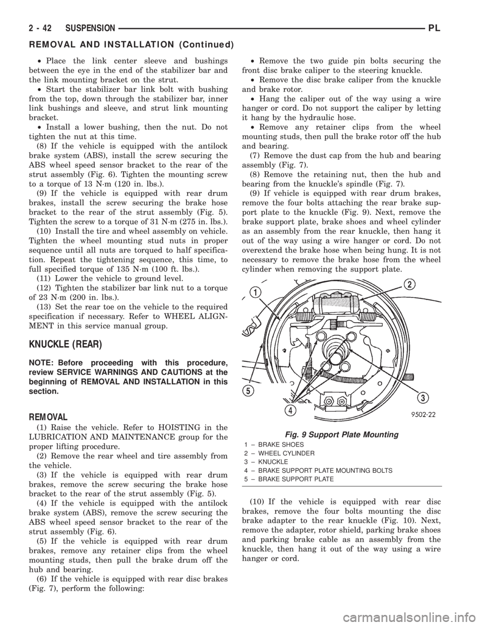
(9) If vehicle is equipped with rear drum brakes,
remove the four bolts attaching the rear brake sup-
port plate to the knuckle (Fig. 9). Next, remove the
brake support plate, brake shoes and wheel cylinder
as an assembly from the rear knuckle, then hang it
out of the way using a wire hanger or cord. Do not
overextend the brake hose when being hung. It is not
necessary to remove the brake hose from the wheel
cylinder when removing the support plate.
(10) If the vehicle is equipped with rear disc
brakes, remove the four bolts mounting the disc
brake adapter to the rear knuckle (Fig. 10). Next,
remove the adapter, rotor shield, parking brake shoes
and parking brake cable as an assembly from the
knuckle, then hang it out of the way using a wire
hanger or cord.Fig. 9 Support Plate Mounting
1 ± BRAKE SHOES
2 ± WHEEL CYLINDER
3 ± KNUCKLE
4 ± BRAKE SUPPORT PLATE MOUNTING BOLTS
5 ± BRAKE SUPPORT PLATE
2 - 42 SUSPENSIONPL
REMOVAL AND INSTALLATION (Continued)
Page 55 of 1285
the front side. Install the nut, but do not completely
tighten it at this time. The nut will need to be tight-
ened when the vehicle is at curb height.
(4) Install the rear bayonet bushing on the tension
strut. Be sure the stepped area of the bushing is
squarely seated into the hole in the knuckle.
(5) Install the rear tension strut retainer, then the
nut. To completely install the nut, place a wrench on
the flat formed into the tension strut and tighten the
nut (Fig. 12). Tighten the nut to a torque of 95 N´m
(70 ft. lbs.).
(6) If vehicle is equipped with rear drum brakes,
install the brake support plate on the knuckle and
attach it using it's four mounting bolts (Fig. 9).
Tighten the mounting bolts to a torque of 75 N´m (55
ft. lbs.).
(7) If the vehicle is equipped with rear disc brakes,
install the disc brake adapter on the knuckle and
attach it using it's four mounting bolts (Fig. 10).
Tighten the mounting bolts to a torque of 75 N´m (55
ft. lbs.).
(8) Install the hub and bearing on the knuckle's
spindle, then install a new retaining nut (Fig. 7). Do
not reuse the original nut. Tighten the nut to a
torque of 217 N´m (160 ft. lbs.).
(9) Install the dust cap on the end of the hub and
bearing (Fig. 7).
(10) If the vehicle is equipped with rear disc
brakes (Fig. 7), install the brake rotor and disc brake
caliper on the knuckle. Install the two guide pin bolts
securing the front disc brake caliper to the steering
knuckle. Tighten the guide pin bolts to a torque of 22
N´m (192 in. lbs.).
(11) If the vehicle is equipped with rear drum
brakes, install the screw securing the brake hose
bracket to the rear of the strut assembly (Fig. 5).
Tighten the screw to a torque of 31 N´m (275 in. lbs.).
(12) If the vehicle is equipped with the antilock
brake system (ABS), install the screw securing the
ABS wheel speed sensor bracket to the rear of the
strut assembly (Fig. 6). Tighten the mounting screw
to a torque of 13 N´m (120 in. lbs.).
(13) Install the tire and wheel assembly. Tighten
the wheel mounting nuts in proper sequence until all
nuts are torqued to half specification. Repeat the
tightening sequence, this time, to full specified
torque of 135 N´m (100 ft. lbs.).
(14) Lower the vehicle to ground level.
(15) Tighten the lateral arm-to-knuckle mounting
bolt nut to a torque of 95 N´m (70 ft. lbs.).
(16) Set the rear toe on the vehicle to the required
specification if necessary. Refer to WHEEL ALIGN-
MENT in this service manual group.HUB AND BEARING (REAR)
NOTE: Before proceeding with this procedure,
review SERVICE WARNINGS AND CAUTIONS at the
beginning of REMOVAL AND INSTALLATION in this
section.
REMOVAL
(1) Raise the vehicle. Refer to HOISTING in the
LUBRICATION AND MAINTENANCE group for the
proper lifting procedure.
(2) Remove the rear wheel and tire assembly from
the vehicle.
(3) If the vehicle is equipped with rear drum
brakes, remove any retainer clips from the wheel
mounting studs, then pull the brake drum off the
hub and bearing.
(4) If the vehicle is equipped with rear disc brakes
(Fig. 7), perform the following:
²Remove the two guide pin bolts securing the
front disc brake caliper to the steering knuckle.
²Remove the disc brake caliper from the knuckle
and brake rotor.
²Hang the caliper out of the way using a wire
hanger or cord. Do not support the caliper by letting
it hang by the hydraulic hose.
²Remove any retainer clips from the wheel
mounting studs, then pull the brake rotor off the hub
and bearing.
(5) Remove the dust cap from the hub and bearing
assembly (Fig. 7).
(6) Remove the retaining nut, then the hub and
bearing from the knuckle's spindle (Fig. 7).
INSTALLATION
(1) Install the hub and bearing on the knuckle's
spindle, then install a new retaining nut (Fig. 7). Do
not reuse the original nut. Tighten the nut to a
torque of 217 N´m (160 ft. lbs.).
(2) Install the dust cap on the end of the hub and
bearing (Fig. 7).
(3) If the vehicle is equipped with rear disc brakes
(Fig. 7), install the brake rotor and disc brake caliper
on the knuckle. Install the two guide pin bolts secur-
ing the front disc brake caliper to the steering
knuckle. Tighten the guide pin bolts to a torque of 22
N´m (192 in. lbs.).
(4) Install the tire and wheel assembly. Tighten
the wheel mounting nuts in proper sequence until all
nuts are torqued to half specification. Repeat the
tightening sequence, this time, to full specified
torque of 135 N´m (100 ft. lbs.).
(5) Lower the vehicle to ground level.
2 - 44 SUSPENSIONPL
REMOVAL AND INSTALLATION (Continued)
Page 80 of 1285
BRAKES
TABLE OF CONTENTS
page page
BASE BRAKE SYSTEM...................... 1ANTILOCK BRAKE SYSTEM................. 65
BASE BRAKE SYSTEM
TABLE OF CONTENTS
page page
DESCRIPTION AND OPERATION
BASE BRAKE SYSTEM OPERATION...........2
BASE BRAKE SYSTEM COMPONENTS.........2
DIAGNOSIS AND TESTING
BASE BRAKE SYSTEM DIAGNOSIS CHARTS....9
POWER BRAKE BOOSTER.................11
DRUM BRAKE AUTOMATIC ADJUSTER........12
BRAKE ROTOR..........................12
BRAKE DRUM...........................15
PROPORTIONING VALVE..................15
BRAKE FLUID CONTAMINATION.............17
SERVICE PROCEDURES
BRAKE FLUID LEVEL CHECKING............17
BASE BRAKE BLEEDING...................17
MASTER CYLINDER BLEEDING.............19
BRAKE TUBE REPAIR.....................19
BRAKE ROTOR MACHINING................21
BRAKE DRUM MACHINING.................22
PARKING BRAKE AUTOMATIC ADJUSTER
LOCK OUT............................22
REMOVAL AND INSTALLATION
SERVICE WARNINGS AND CAUTIONS........23
BRAKE PEDAL...........................24
BRAKE LAMP SWITCH....................27
MASTER CYLINDER......................28
BRAKE FLUID RESERVOIR.................29
BRAKE FLUID LEVEL SWITCH..............30
POWER BRAKE BOOSTER.................30
PROPORTIONING VALVE..................32
BRAKES TUBES AND HOSES...............33
DISC BRAKE CALIPER (FRONT).............33
DISC BRAKE SHOES (FRONT)..............35BRAKE ROTOR (FRONT)...................37
DISC BRAKE CALIPER (REAR)..............38
DISC BRAKE SHOES (REAR)...............39
BRAKE ROTOR (REAR)....................41
DRUM BRAKE WHEEL CYLINDER (REAR).....41
DRUM BRAKE SHOES (REAR)..............43
BRAKE DRUM (REAR).....................45
DRUM BRAKE SHOE SUPPORT PLATE
(REAR)...............................46
PARKING BRAKE LEVER...................48
PARKING BRAKE CABLE (REAR)............49
PARKING BRAKE SHOES (REAR DISC
BRAKE)...............................53
DISASSEMBLY AND ASSEMBLY
DISC BRAKE CALIPER (FRONT AND REAR)....55
CLEANING AND INSPECTION
BRAKE TUBES AND HOSES................59
DISC BRAKES (FRONT)....................59
DISC BRAKES (REAR).....................60
DRUM BRAKES (REAR)....................60
ADJUSTMENTS
BRAKE LAMP SWITCH....................61
DRUM BRAKE SHOES.....................61
PARKING BRAKE SHOES (REAR DISC
BRAKES).............................62
SPECIFICATIONS
BRAKE FLUID...........................63
BRAKE ACTUATION SYSTEM...............63
BRAKE FASTENER TORQUE
SPECIFICATIONS.......................63
SPECIAL TOOLS
BASE BRAKE SYSTEM....................64
PLBRAKES 5 - 1
Page 83 of 1285
Proportioning valves balance front to rear braking
by controlling the brake fluid hydraulic pressure to
the rear brakes. Under light pedal application, the
proportioning valve allows normal fluid flow to the
rear brakes. Under higher pedal effort, the valve
reduces fluid pressure to the rear brakes.
The non-antilock master cylinder is a four-outlet
design with two screw-in proportioning valves
attached directly to the master cylinder housing (Fig.
3). One proportioning valve controls each rear brake.
BRAKE TUBES AND HOSES
The purpose of the brake tubes and flex hoses is to
transfer the pressurized brake fluid developed by the
master cylinder to the brakes at each wheel of the
vehicle. The flex hoses connect the chassis brake
tubes, which are mounted to the vehicle's underbody,
to the brake at each wheel, allowing for movement of
the vehicle's suspension. The brake tubes are steel
with a corrosion-resistant nylon coating applied to
the external surfaces. The flex hoses are made of
reinforced rubber.
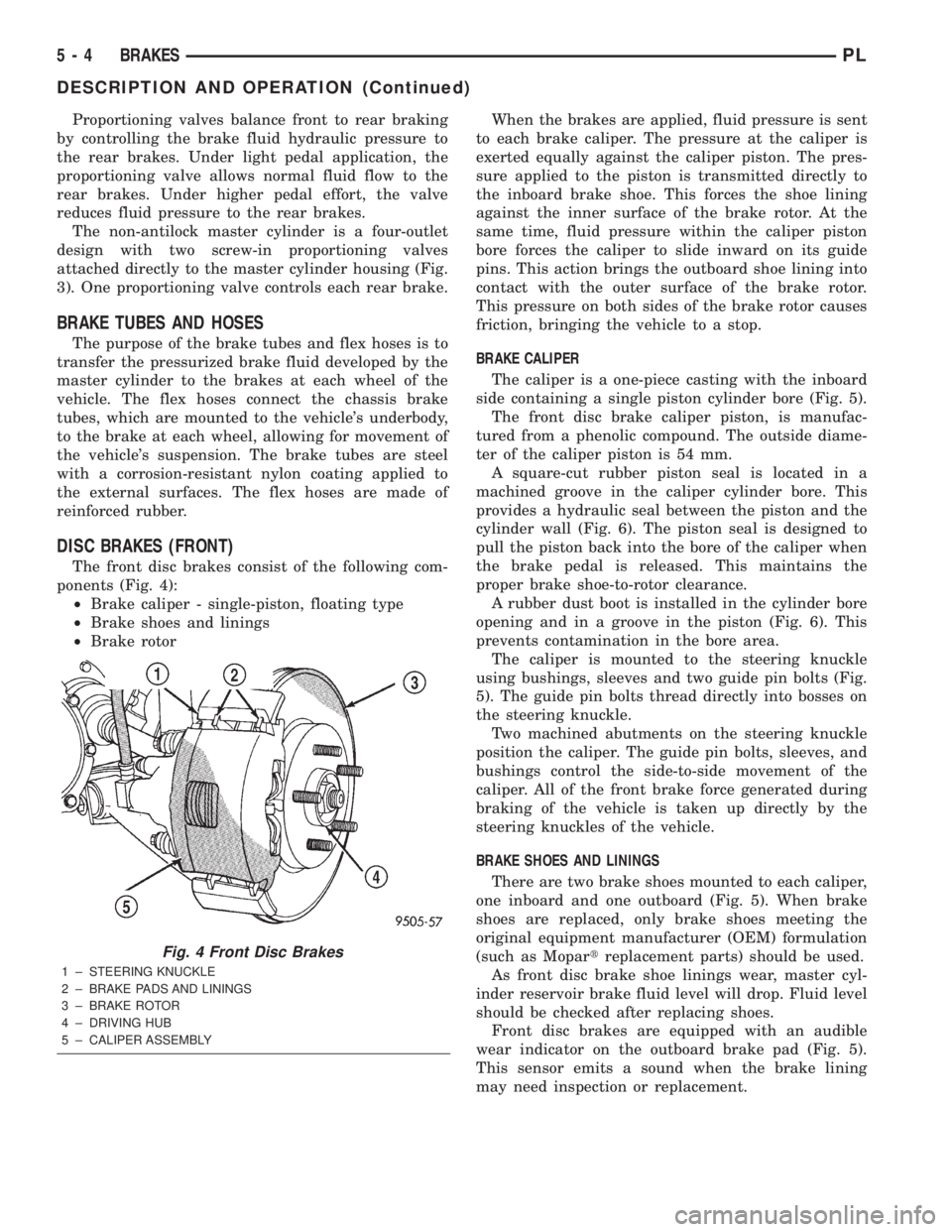
DISC BRAKES (FRONT)
The front disc brakes consist of the following com-
ponents (Fig. 4):
²Brake caliper - single-piston, floating type
²Brake shoes and linings
²Brake rotorWhen the brakes are applied, fluid pressure is sent
to each brake caliper. The pressure at the caliper is
exerted equally against the caliper piston. The pres-
sure applied to the piston is transmitted directly to
the inboard brake shoe. This forces the shoe lining
against the inner surface of the brake rotor. At the
same time, fluid pressure within the caliper piston
bore forces the caliper to slide inward on its guide
pins. This action brings the outboard shoe lining into
contact with the outer surface of the brake rotor.
This pressure on both sides of the brake rotor causes
friction, bringing the vehicle to a stop.
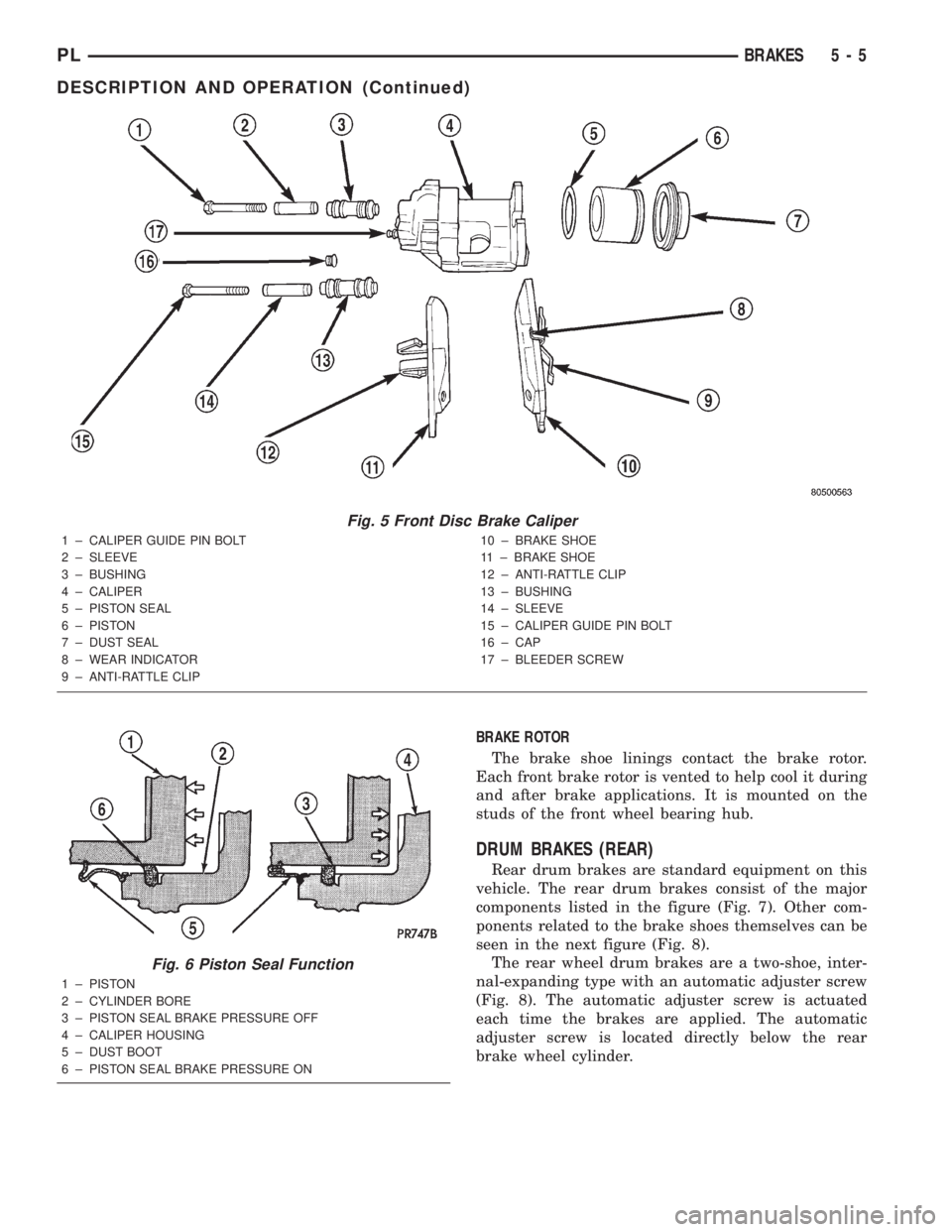
BRAKE CALIPER
The caliper is a one-piece casting with the inboard
side containing a single piston cylinder bore (Fig. 5).
The front disc brake caliper piston, is manufac-
tured from a phenolic compound. The outside diame-
ter of the caliper piston is 54 mm.
A square-cut rubber piston seal is located in a
machined groove in the caliper cylinder bore. This
provides a hydraulic seal between the piston and the
cylinder wall (Fig. 6). The piston seal is designed to
pull the piston back into the bore of the caliper when
the brake pedal is released. This maintains the
proper brake shoe-to-rotor clearance.
A rubber dust boot is installed in the cylinder bore
opening and in a groove in the piston (Fig. 6). This
prevents contamination in the bore area.
The caliper is mounted to the steering knuckle
using bushings, sleeves and two guide pin bolts (Fig.
5). The guide pin bolts thread directly into bosses on
the steering knuckle.
Two machined abutments on the steering knuckle
position the caliper. The guide pin bolts, sleeves, and
bushings control the side-to-side movement of the
caliper. All of the front brake force generated during
braking of the vehicle is taken up directly by the
steering knuckles of the vehicle.
BRAKE SHOES AND LININGS
There are two brake shoes mounted to each caliper,
one inboard and one outboard (Fig. 5). When brake
shoes are replaced, only brake shoes meeting the
original equipment manufacturer (OEM) formulation
(such as Mopartreplacement parts) should be used.
As front disc brake shoe linings wear, master cyl-
inder reservoir brake fluid level will drop. Fluid level
should be checked after replacing shoes.
Front disc brakes are equipped with an audible
wear indicator on the outboard brake pad (Fig. 5).
This sensor emits a sound when the brake lining
may need inspection or replacement.
Fig. 4 Front Disc Brakes
1 ± STEERING KNUCKLE
2 ± BRAKE PADS AND LININGS
3 ± BRAKE ROTOR
4 ± DRIVING HUB
5 ± CALIPER ASSEMBLY
5 - 4 BRAKESPL
DESCRIPTION AND OPERATION (Continued)
Page 84 of 1285
BRAKE ROTOR
The brake shoe linings contact the brake rotor.
Each front brake rotor is vented to help cool it during
and after brake applications. It is mounted on the
studs of the front wheel bearing hub.
DRUM BRAKES (REAR)
Rear drum brakes are standard equipment on this
vehicle. The rear drum brakes consist of the major
components listed in the figure (Fig. 7). Other com-
ponents related to the brake shoes themselves can be
seen in the next figure (Fig. 8).
The rear wheel drum brakes are a two-shoe, inter-
nal-expanding type with an automatic adjuster screw
(Fig. 8). The automatic adjuster screw is actuated
each time the brakes are applied. The automatic
adjuster screw is located directly below the rear
brake wheel cylinder.
Fig. 5 Front Disc Brake Caliper
1 ± CALIPER GUIDE PIN BOLT
2 ± SLEEVE
3 ± BUSHING
4 ± CALIPER
5 ± PISTON SEAL
6 ± PISTON
7 ± DUST SEAL
8 ± WEAR INDICATOR
9 ± ANTI-RATTLE CLIP10 ± BRAKE SHOE
11 ± BRAKE SHOE
12 ± ANTI-RATTLE CLIP
13 ± BUSHING
14 ± SLEEVE
15 ± CALIPER GUIDE PIN BOLT
16 ± CAP
17 ± BLEEDER SCREW
Fig. 6 Piston Seal Function
1 ± PISTON
2 ± CYLINDER BORE
3 ± PISTON SEAL BRAKE PRESSURE OFF
4 ± CALIPER HOUSING
5 ± DUST BOOT
6 ± PISTON SEAL BRAKE PRESSURE ON
PLBRAKES 5 - 5
DESCRIPTION AND OPERATION (Continued)
Page 85 of 1285
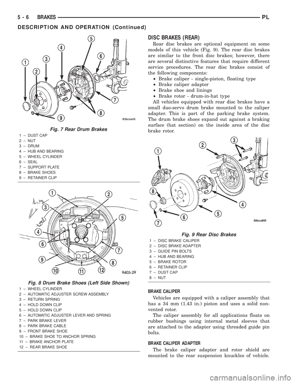
DISC BRAKES (REAR)
Rear disc brakes are optional equipment on some
models of this vehicle (Fig. 9). The rear disc brakes
are similar to the front disc brakes; however, there
are several distinctive features that require different
service procedures. The rear disc brakes consist of
the following components:
²Brake caliper - single-piston, floating type
²Brake caliper adapter
²Brake shoe and linings
²Brake rotor - drum-in-hat type
All vehicles equipped with rear disc brakes have a
small duo-servo drum brake mounted to the caliper
adapter. This is part of the parking brake system.
The drum brake shoes expand out against a braking
surface (hat section) on the inside area of the disc
brake rotor.
BRAKE CALIPER
Vehicles are equipped with a caliper assembly that
has a 34 mm (1.43 in.) piston and uses a solid non-
vented rotor.
The caliper assembly for all applications floats on
rubber bushings using internal metal sleeves that
are attached to the adapter using threaded guide pin
bolts.
BRAKE CALIPER ADAPTER
The brake caliper adapter and rotor shield are
mounted to the rear suspension knuckles of vehicle.
Fig. 7 Rear Drum Brakes
1 ± DUST CAP
2 ± NUT
3 ± DRUM
4 ± HUB AND BEARING
5 ± WHEEL CYLINDER
6 ± SEAL
7 ± SUPPORT PLATE
8 ± BRAKE SHOES
9 ± RETAINER CLIP
Fig. 8 Drum Brake Shoes (Left Side Shown)
1 ± WHEEL CYLINDER
2 ± AUTOMATIC ADJUSTER SCREW ASSEMBLY
3 ± RETURN SPRING
4 ± HOLD DOWN CLIP
5 ± HOLD DOWN CLIP
6 ± AUTOMATIC ADJUSTER LEVER AND SPRING
7 ± PARK BRAKE LEVER
8 ± PARK BRAKE CABLE
9 ± FRONT BRAKE SHOE
10 ± BRAKE SHOE TO ANCHOR SPRING
11 ± BRAKE ANCHOR PLATE
12 ± REAR BRAKE SHOE
Fig. 9 Rear Disc Brakes
1 ± DISC BRAKE CALIPER
2 ± DISC BRAKE ADAPTER
3 ± GUIDE PIN BOLTS
4 ± HUB AND BEARING
5 ± BRAKE ROTOR
6 ± RETAINER CLIP
7 ± DUST CAP
8 ± NUT
5 - 6 BRAKESPL
DESCRIPTION AND OPERATION (Continued)
Page 86 of 1285
The adapter is used to mount the brake caliper to the
vehicle (Fig. 9). The adapter has two machined abut-
ments, which are used to position and align the cal-
iper and brake pads for movement inboard and
outboard. The adapter also mounts the parking brake
shoes and actuating cables to the vehicle.
PARKING BRAKES
The parking brakes (Fig. 4) consist of the following
components:
²Hand-operated park brake lever - automatic-ad-
justing
²Parking brake cables
²Actuation levers and struts
²Duo-servo parking brake assembly (rear disc
only)
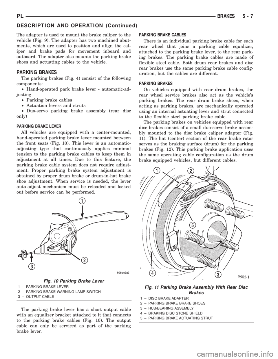
PARKING BRAKE LEVER
All vehicles are equipped with a center-mounted,
hand-operated parking brake lever mounted between
the front seats (Fig. 10). This lever is an automatic-
adjusting type that continuously applies minimal
tension to the parking brake cables to keep them in
adjustment at all times. Due to this feature, the
parking brake cable system does not require adjust-
ment. Proper parking brake system adjustment is
obtained by proper drum brake or drum-in-hat brake
shoe adjustment. When service is needed, the lever
auto-adjust mechanism must be reloaded and locked
out before service can be performed.
The parking brake lever has a short output cable
with an equalizer bracket attached to it that connects
to the parking brake cables (Fig. 10). The output
cable can only be serviced as part of the parking
brake lever.PARKING BRAKE CABLES
There is an individual parking brake cable for each
rear wheel that joins a parking cable equalizer,
attached to the parking brake lever, to the rear park-
ing brakes. The parking brake cables are made of
flexible steel cable. Both drum rear brakes and disc
rear brakes use the same parking brake cable config-
uration, but the cables are different.
PARKING BRAKES
On vehicles equipped with rear drum brakes, the
rear wheel service brakes also act as the vehicle's
parking brakes. The rear drum brake shoes, when
acting as parking brakes, are mechanically operated
using an internal actuating lever and strut connected
to the flexible steel parking brake cable.
The parking brakes on vehicles equipped with rear
disc brakes consist of a small duo-servo brake assem-
bly mounted to the disc brake caliper adapter (Fig.
11). The hat (center) section of the rear brake rotor
serves as the braking surface (drum) for the parking
brakes (Fig. 12). This parking brake application uses
the same operating cable configuration as the drum
brake equipped vehicles, but different cables.
Fig. 10 Parking Brake Lever
1 ± PARKING BRAKE LEVER
2 ± PARKING BRAKE WARNING LAMP SWITCH
3 ± OUTPUT CABLEFig. 11 Parking Brake Assembly With Rear Disc
Brakes
1 ± DISC BRAKE ADAPTER
2 ± PARKING BRAKE BRAKE SHOES
3 ± HUB/BEARING ASSEMBLY
4 ± BRAKING DISC STONE SHIELD
5 ± PARKING BRAKE ACTUATING STRUT
PLBRAKES 5 - 7
DESCRIPTION AND OPERATION (Continued)