(9) While holding the stud of the tie rod stationary
with a wrench, tighten the attaching nut (Fig. 14).
(10) Using a crowfoot wrench attached to a torque
wrench, tighten the attaching nut to 75 N´m (55 ft.
lbs.).
(11) Install the tire and wheel assembly.
(12) Lower the vehicle.
(13) Adjust the front toe setting on the vehicle.
Refer to WHEEL ALIGNMENT in the SUSPENSION
service manual group.
SPECIFICATIONS
POWER STEERING GEAR FASTENER TORQUE
SPECIFICATIONS
DESCRIPTION TORQUE
FRONT SUSPENSION CROSSMEMBER:
Front Mounting Bolts..... 142N´m(105 ft. lbs.)
Rear Mounting Bolts..... 203N´m(150 ft. lbs.)
STEERING GEAR:
Mounting Bolts........... 61N´m(45ft.lbs.)
OUTER TIE ROD:
Steering Knuckle Nut...... 55N´m(40ft.lbs.)
TieRodJamNut .......... 75N´m(55ft.lbs.)
POWER STEERING HOSE:
Tube Nuts............... 34N´m(25ft.lbs.)
SPECIAL TOOLS
POWER STEERING GEAR
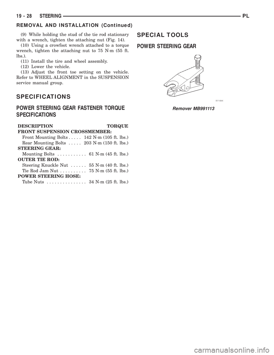
Remover MB991113
19 - 28 STEERINGPL
REMOVAL AND INSTALLATION (Continued)