2000 DODGE NEON run flat
[x] Cancel search: run flatPage 16 of 1285
SERVICE PROCEDURES
CURB HEIGHT MEASUREMENT
The wheel alignment is to be checked and all align-
ment adjustments made with the vehicle at its
required curb height specification.
Vehicle height is to be checked with the vehicle on
a flat, level surface, preferably a vehicle alignment
rack. The tires are to be inflated to the recommended
pressure. All tires are to be the same size as stan-
dard equipment. Vehicle height is checked with the
fuel tank full of fuel, and no passenger or luggage
compartment load.
Vehicle height is not adjustable. If the measure-
ment is not within specifications, inspect the vehicle
for bent or weak suspension components. Compare
the parts tag on the suspect coil spring(s) to the
parts book and the vehicle sales code, checking for a
match. Once removed from the vehicle, compare thecoil spring height to a correct new or known good coil
spring. The heights should vary if the suspect spring
is weak.
NOTE: Prior to reading the curb height measure-
ment, the front an rear of the vehicle should be
jounced. Induce jounce by grasping the center of
the rear, then front bumper (or fascia) and jouncing
the vehicle an equal number of times. Release the
bumper at the bottom of the jounce cycle.
(1) Measure from the inboard edge of the wheel
opening fender lip directly above the wheel center
(spindle), to the floor or alignment rack surface.
(2) When measuring, maximum left-to-right differ-
ential is not to exceed 10 mm (0.39 in.).
(3) Compare the measurements to specifications
listed in the following CURB HEIGHT SPECIFICA-
TIONS chart.
CURB HEIGHT SPECIFICATIONS
VEHICLE FRONT REAR
ALL NEON672 mm68 mm 679 mm68mm
26.46 in.60.32 in. 26.73 in.60.32 in.
WHEEL ALIGNMENT
PRE-WHEEL ALIGNMENT VEHICLE INSPECTION
CAUTION: If during the inspection the front sus-
pension crossmember shows any sign of impact
damage, the steering column lower coupling must
be inspected. Refer to DIAGNOSIS AND TESTING in
the STEERING group in this service manual.
Before any attempt is made to change or correct
the wheel alignment, the following inspection and
necessary corrections must be made to the vehicle to
ensure proper alignment.
(1) Be sure the fuel tank is full of fuel. If the fuel
tank is not full, the reduction in weight will affect
the curb height of the vehicle and the alignment
specifications.
(2) The passenger and luggage compartments of
the vehicle should be free of any load that is not fac-
tory equipment.
(3) Check the tires on the vehicle. The tires are to
be inflated to the recommended air pressure. All tires
must be the same size and in good condition with
approximately the same tread wear.
(4) Check the front tire and wheel assemblies for
excessive radial runout.(5) Inspect all suspension component fasteners for
looseness and torque.
(6) Inspect the lower front ball joints and all steer-
ing linkage for looseness and any sign of wear or
damage.
(7) Inspect the rubber bushings on all the suspen-
sion components for signs of wear or deterioration. If
any bushings show signs of wear or deterioration,
they should be replaced prior to aligning the vehicle.
WHEEL ALIGNMENT SETUP
(1) Position the vehicle on an alignment rack.
(2) Install all required alignment equipment on
the vehicle, per the alignment equipment manufac-
turer's instructions. On this vehicle, a four-wheel
alignment is recommended.
NOTE: Prior to reading the vehicle's alignment
readouts, the front and rear of vehicle should be
jounced. Induce jounce (rear first, then front) by
grasping the center of the bumper and jouncing
each end of vehicle an equal number of times. The
bumper should always be released when vehicle is
at the bottom of the jounce cycle.
(3) Read the vehicle's current front and rear align-
ment settings. Compare the vehicle's current align-
ment settings to the vehicle specifications for camber,
caster and toe-in. Refer to WHEEL ALIGNMENT
PLSUSPENSION 2 - 5
Page 49 of 1285
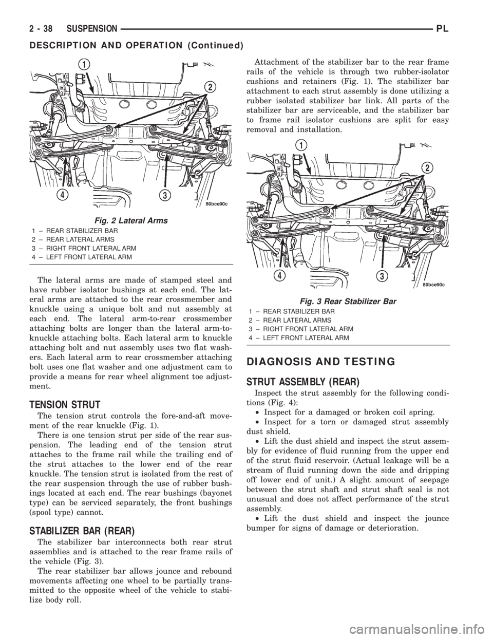
The lateral arms are made of stamped steel and
have rubber isolator bushings at each end. The lat-
eral arms are attached to the rear crossmember and
knuckle using a unique bolt and nut assembly at
each end. The lateral arm-to-rear crossmember
attaching bolts are longer than the lateral arm-to-
knuckle attaching bolts. Each lateral arm to knuckle
attaching bolt and nut assembly uses two flat wash-
ers. Each lateral arm to rear crossmember attaching
bolt uses one flat washer and one adjustment cam to
provide a means for rear wheel alignment toe adjust-
ment.
TENSION STRUT
The tension strut controls the fore-and-aft move-
ment of the rear knuckle (Fig. 1).
There is one tension strut per side of the rear sus-
pension. The leading end of the tension strut
attaches to the frame rail while the trailing end of
the strut attaches to the lower end of the rear
knuckle. The tension strut is isolated from the rest of
the rear suspension through the use of rubber bush-
ings located at each end. The rear bushings (bayonet
type) can be serviced separately, the front bushings
(spool type) cannot.
STABILIZER BAR (REAR)
The stabilizer bar interconnects both rear strut
assemblies and is attached to the rear frame rails of
the vehicle (Fig. 3).
The rear stabilizer bar allows jounce and rebound
movements affecting one wheel to be partially trans-
mitted to the opposite wheel of the vehicle to stabi-
lize body roll.Attachment of the stabilizer bar to the rear frame
rails of the vehicle is through two rubber-isolator
cushions and retainers (Fig. 1). The stabilizer bar
attachment to each strut assembly is done utilizing a
rubber isolated stabilizer bar link. All parts of the
stabilizer bar are serviceable, and the stabilizer bar
to frame rail isolator cushions are split for easy
removal and installation.
DIAGNOSIS AND TESTING
STRUT ASSEMBLY (REAR)
Inspect the strut assembly for the following condi-
tions (Fig. 4):
²Inspect for a damaged or broken coil spring.
²Inspect for a torn or damaged strut assembly
dust shield.
²Lift the dust shield and inspect the strut assem-
bly for evidence of fluid running from the upper end
of the strut fluid reservoir. (Actual leakage will be a
stream of fluid running down the side and dripping
off lower end of unit.) A slight amount of seepage
between the strut shaft and strut shaft seal is not
unusual and does not affect performance of the strut
assembly.
²Lift the dust shield and inspect the jounce
bumper for signs of damage or deterioration.
Fig. 2 Lateral Arms
1 ± REAR STABILIZER BAR
2 ± REAR LATERAL ARMS
3 ± RIGHT FRONT LATERAL ARM
4 ± LEFT FRONT LATERAL ARM
Fig. 3 Rear Stabilizer Bar
1 ± REAR STABILIZER BAR
2 ± REAR LATERAL ARMS
3 ± RIGHT FRONT LATERAL ARM
4 ± LEFT FRONT LATERAL ARM
2 - 38 SUSPENSIONPL
DESCRIPTION AND OPERATION (Continued)
Page 104 of 1285
(10) If the vehicle is equipped with antilock
brakes, carefully push the power brake booster for-
ward until the booster contacts the ABS ICU mount-
ing bracket.
(11) If the vehicle does not have antilock brakes,
carefully push the power brake booster forward one
to two inches being careful not to stretch the brake
lines from the master cylinder to the brakes.
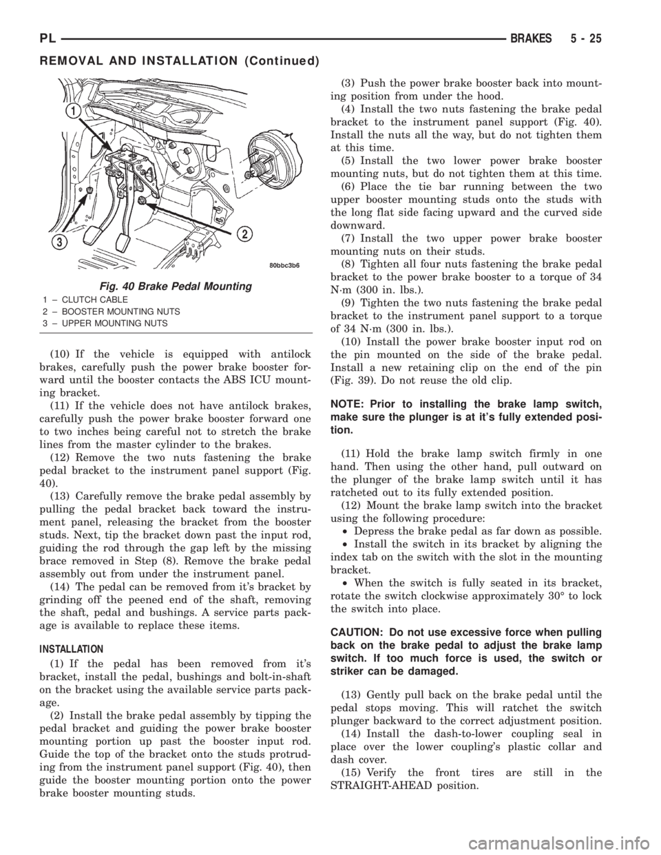
(12) Remove the two nuts fastening the brake
pedal bracket to the instrument panel support (Fig.
40).
(13) Carefully remove the brake pedal assembly by
pulling the pedal bracket back toward the instru-
ment panel, releasing the bracket from the booster
studs. Next, tip the bracket down past the input rod,
guiding the rod through the gap left by the missing
brace removed in Step (8). Remove the brake pedal
assembly out from under the instrument panel.
(14) The pedal can be removed from it's bracket by
grinding off the peened end of the shaft, removing
the shaft, pedal and bushings. A service parts pack-
age is available to replace these items.
INSTALLATION
(1) If the pedal has been removed from it's
bracket, install the pedal, bushings and bolt-in-shaft
on the bracket using the available service parts pack-
age.
(2) Install the brake pedal assembly by tipping the
pedal bracket and guiding the power brake booster
mounting portion up past the booster input rod.
Guide the top of the bracket onto the studs protrud-
ing from the instrument panel support (Fig. 40), then
guide the booster mounting portion onto the power
brake booster mounting studs.(3) Push the power brake booster back into mount-
ing position from under the hood.
(4) Install the two nuts fastening the brake pedal
bracket to the instrument panel support (Fig. 40).
Install the nuts all the way, but do not tighten them
at this time.
(5) Install the two lower power brake booster
mounting nuts, but do not tighten them at this time.
(6) Place the tie bar running between the two
upper booster mounting studs onto the studs with
the long flat side facing upward and the curved side
downward.
(7) Install the two upper power brake booster
mounting nuts on their studs.
(8) Tighten all four nuts fastening the brake pedal
bracket to the power brake booster to a torque of 34
N´m (300 in. lbs.).
(9) Tighten the two nuts fastening the brake pedal
bracket to the instrument panel support to a torque
of 34 N´m (300 in. lbs.).
(10) Install the power brake booster input rod on
the pin mounted on the side of the brake pedal.
Install a new retaining clip on the end of the pin
(Fig. 39). Do not reuse the old clip.
NOTE: Prior to installing the brake lamp switch,
make sure the plunger is at it's fully extended posi-
tion.
(11) Hold the brake lamp switch firmly in one
hand. Then using the other hand, pull outward on
the plunger of the brake lamp switch until it has
ratcheted out to its fully extended position.
(12) Mount the brake lamp switch into the bracket
using the following procedure:
²Depress the brake pedal as far down as possible.
²Install the switch in its bracket by aligning the
index tab on the switch with the slot in the mounting
bracket.
²When the switch is fully seated in its bracket,
rotate the switch clockwise approximately 30É to lock
the switch into place.
CAUTION: Do not use excessive force when pulling
back on the brake pedal to adjust the brake lamp
switch. If too much force is used, the switch or
striker can be damaged.
(13) Gently pull back on the brake pedal until the
pedal stops moving. This will ratchet the switch
plunger backward to the correct adjustment position.
(14) Install the dash-to-lower coupling seal in
place over the lower coupling's plastic collar and
dash cover.
(15) Verify the front tires are still in the
STRAIGHT-AHEAD position.
Fig. 40 Brake Pedal Mounting
1 ± CLUTCH CABLE
2 ± BOOSTER MOUNTING NUTS
3 ± UPPER MOUNTING NUTS
PLBRAKES 5 - 25
REMOVAL AND INSTALLATION (Continued)
Page 349 of 1285
²Clockspring assembly
²Steering Column Assembly w/Lower Steering
Column Coupler
PASSENGER AIRBAG
After a Passenger Airbag Module has been
deployed, replace the following components because
they cannot be reused.
²Passenger Airbag Module
Inspect all the attaching hardware and instrument
panel for damage. If damage is evident, components
should be replaced.
HANDLING AIRBAG MODULES
DEPLOYED AIRBAG MODULE
The vehicle interior may contain a very small
amount of sodium hydroxide powder, a by-product of
airbag deployment. Sodium hydroxide powder can
irritate the skin, eyes, nose and throat. Wear safety
glasses, rubber gloves, and long sleeved clothing
when cleaning any of the powder residue from the
vehicle.
If you find that the cleanup is irritating your skin,
run cool water over the affected area. Also, if you
experience nasal or throat irritation, exit the vehicle
for fresh air until the irritation ceases. If irritation
continues, see a physician.
UNDEPLOYED AIRBAG MODULE
The airbag modules must be stored in its original
special container until used for service. At no time
should a source of electricity be permitted near the
inflator on the back of an airbag module. When car-
rying or handling an undeployed airbag module, the
trim side of the airbag should be pointing away from
the body to minimize possibility of injury if acciden-
tal deployment occurs. Do not place undeployed air-
bag face down on a solid surface, the airbag will
propel into the air if accidentally deployment occurs.
MAINTENANCE INSPECTION
(1) Check the airbag warning lamp for proper
operation as follows:
(a) Turn ignition switch to the ON position, the
airbag warning lamp should light. If not, test the
system using a DRB llltscan tool and the proper
Body Diagnostic Procedures Manual.
(b) The airbag warning lamp lights, but fails to
go out after eight seconds. Test the system using a
DRB llltscan tool and the proper Body Diagnostic
Procedures Manual.
(c) After correcting active malfunction erase
stored Diagnostic Trouble Codes (DTC's).
REMOVAL AND INSTALLATION
AIRBAG CONTROL MODULE (ACM)
WARNING: THE ACM CONTAINS THE SENSING
ELEMENT AND A SAFING SENSOR WHICH
ENABLES THE SYSTEM TO DEPLOY THE AIR-
BAGS. TO AVOID ACCIDENTAL DEPLOYMENT,
NEVER CONNECT ACM ELECTRICALLY TO THE
SYSTEM WHILE VEHICLE BATTERY IS CON-
NECTED.
DISCONNECT AND ISOLATE THE BATTERY NEG-
ATIVE (GROUND) CABLE BEFORE BEGINNING ANY
AIRBAG SYSTEM COMPONENT REMOVAL OR
INSTALLATION PROCEDURE. THIS WILL DISABLE
THE AIRBAG SYSTEM. FAILURE TO DISCONNECT
BATTERY COULD RESULT IN ACCIDENTAL AIRBAG
DEPLOYMENT AND POSSIBLE PERSONAL INJURY.
ALLOW SYSTEM CAPACITOR TO DISCHARGE
FOR 1 MINUTE BEFORE REMOVING ANY AIRBAG
COMPONENTS.
REMOVAL
(1) Disconnect and isolate the battery negative
cable (Fig. 4).
(2) Remove center console. Refer to Group 23 Body,
Floor Console Removal and Installation.
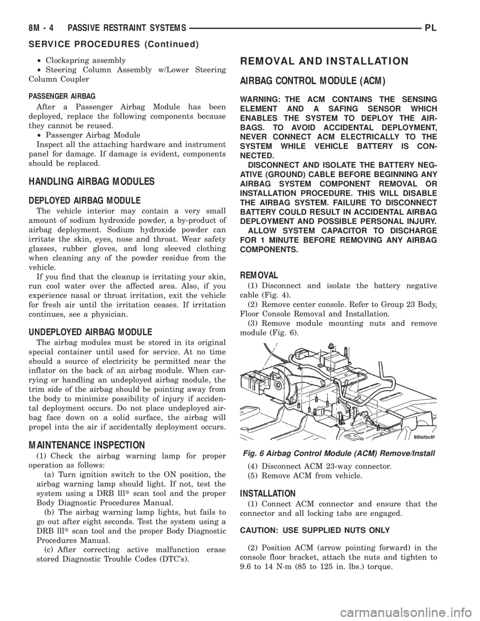
(3) Remove module mounting nuts and remove
module (Fig. 6).
(4) Disconnect ACM 23-way connector.
(5) Remove ACM from vehicle.
INSTALLATION
(1) Connect ACM connector and ensure that the
connector and all locking tabs are engaged.
CAUTION: USE SUPPLIED NUTS ONLY
(2) Position ACM (arrow pointing forward) in the
console floor bracket, attach the nuts and tighten to
9.6 to 14 N´m (85 to 125 in. lbs.) torque.
Fig. 6 Airbag Control Module (ACM) Remove/Install
8M - 4 PASSIVE RESTRAINT SYSTEMSPL
SERVICE PROCEDURES (Continued)
Page 877 of 1285
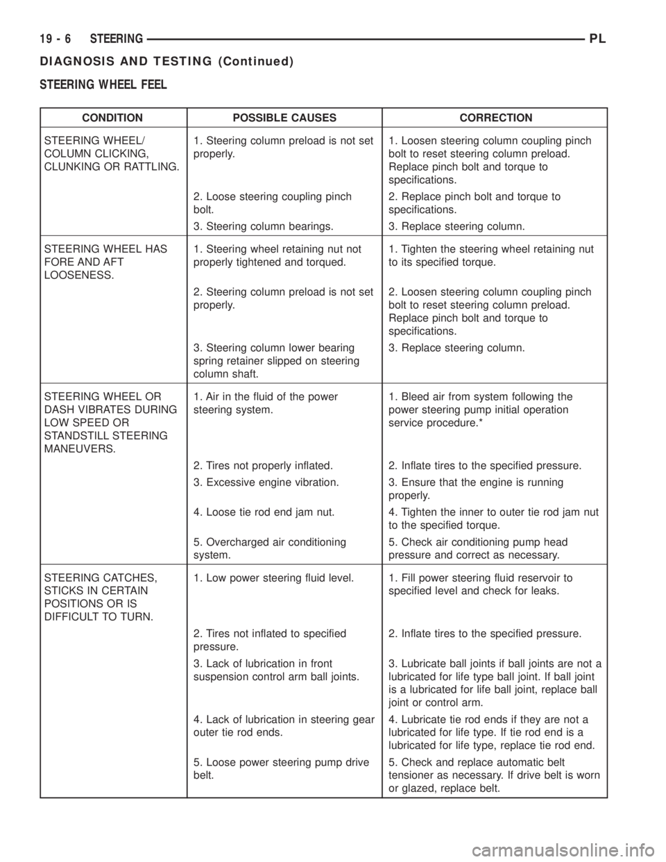
STEERING WHEEL FEEL
CONDITION POSSIBLE CAUSES CORRECTION
STEERING WHEEL/
COLUMN CLICKING,
CLUNKING OR RATTLING.1. Steering column preload is not set
properly.1. Loosen steering column coupling pinch
bolt to reset steering column preload.
Replace pinch bolt and torque to
specifications.
2. Loose steering coupling pinch
bolt.2. Replace pinch bolt and torque to
specifications.
3. Steering column bearings. 3. Replace steering column.
STEERING WHEEL HAS
FORE AND AFT
LOOSENESS.1. Steering wheel retaining nut not
properly tightened and torqued.1. Tighten the steering wheel retaining nut
to its specified torque.
2. Steering column preload is not set
properly.2. Loosen steering column coupling pinch
bolt to reset steering column preload.
Replace pinch bolt and torque to
specifications.
3. Steering column lower bearing
spring retainer slipped on steering
column shaft.3. Replace steering column.
STEERING WHEEL OR
DASH VIBRATES DURING
LOW SPEED OR
STANDSTILL STEERING
MANEUVERS.1. Air in the fluid of the power
steering system.1. Bleed air from system following the
power steering pump initial operation
service procedure.*
2. Tires not properly inflated. 2. Inflate tires to the specified pressure.
3. Excessive engine vibration. 3. Ensure that the engine is running
properly.
4. Loose tie rod end jam nut. 4. Tighten the inner to outer tie rod jam nut
to the specified torque.
5. Overcharged air conditioning
system.5. Check air conditioning pump head
pressure and correct as necessary.
STEERING CATCHES,
STICKS IN CERTAIN
POSITIONS OR IS
DIFFICULT TO TURN.1. Low power steering fluid level. 1. Fill power steering fluid reservoir to
specified level and check for leaks.
2. Tires not inflated to specified
pressure.2. Inflate tires to the specified pressure.
3. Lack of lubrication in front
suspension control arm ball joints.3. Lubricate ball joints if ball joints are not a
lubricated for life type ball joint. If ball joint
is a lubricated for life ball joint, replace ball
joint or control arm.
4. Lack of lubrication in steering gear
outer tie rod ends.4. Lubricate tie rod ends if they are not a
lubricated for life type. If tie rod end is a
lubricated for life type, replace tie rod end.
5. Loose power steering pump drive
belt.5. Check and replace automatic belt
tensioner as necessary. If drive belt is worn
or glazed, replace belt.
19 - 6 STEERINGPL
DIAGNOSIS AND TESTING (Continued)
Page 1073 of 1285
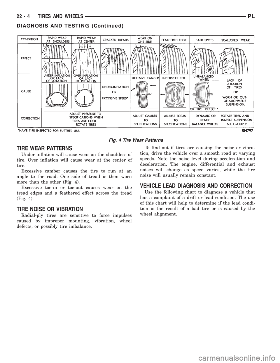
TIRE WEAR PATTERNS
Under inflation will cause wear on the shoulders of
tire. Over inflation will cause wear at the center of
tire.
Excessive camber causes the tire to run at an
angle to the road. One side of tread is then worn
more than the other (Fig. 4).
Excessive toe-in or toe-out causes wear on the
tread edges and a feathered effect across the tread
(Fig. 4).
TIRE NOISE OR VIBRATION
Radial-ply tires are sensitive to force impulses
caused by improper mounting, vibration, wheel
defects, or possibly tire imbalance.To find out if tires are causing the noise or vibra-
tion, drive the vehicle over a smooth road at varying
speeds. Note the noise level during acceleration and
deceleration. The engine, differential and exhaust
noises will change as speed varies, while the tire
noise will usually remain constant.
VEHICLE LEAD DIAGNOSIS AND CORRECTION
Use the following chart to diagnose a vehicle that
has a complaint of a drift or lead condition. The use
of this chart will help to determine if the lead condi-
tion is the result of a bad tire or is caused by the
wheel alignment.
Fig. 4 Tire Wear Patterns
22 - 4 TIRES AND WHEELSPL
DIAGNOSIS AND TESTING (Continued)
Page 1076 of 1285
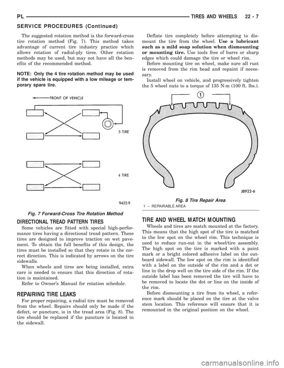
The suggested rotation method is the forward-cross
tire rotation method (Fig. 7). This method takes
advantage of current tire industry practice which
allows rotation of radial-ply tires. Other rotation
methods may be used, but may not have all the ben-
efits of the recommended method.
NOTE: Only the 4 tire rotation method may be used
if the vehicle is equipped with a low mileage or tem-
porary spare tire.
DIRECTIONAL TREAD PATTERN TIRES
Some vehicles are fitted with special high-perfor-
mance tires having a directional tread pattern. These
tires are designed to improve traction on wet pave-
ment. To obtain the full benefits of this design, the
tires must be installed so that they rotate in the cor-
rect direction. This is indicated by arrows on the tire
sidewalls.
When wheels and tires are being installed, extra
care is needed to ensure that this direction of rota-
tion is maintained.
Refer to Owner's Manual for rotation schedule.
REPAIRING TIRE LEAKS
For proper repairing, a radial tire must be removed
from the wheel. Repairs should only be made if the
defect, or puncture, is in the tread area (Fig. 8). The
tire should be replaced if the puncture is located in
the sidewall.Deflate tire completely before attempting to dis-
mount the tire from the wheel.Use a lubricant
such as a mild soap solution when dismounting
or mounting tire.Use tools free of burrs or sharp
edges which could damage the tire or wheel rim.
Before mounting tire on wheel, make sure all rust
is removed from the rim bead and repaint if neces-
sary.
Install wheel on vehicle, and progressively tighten
the 5 wheel nuts to a torque of 135 N´m (100 ft. lbs.).
TIRE AND WHEEL MATCH MOUNTING
Wheels and tires are match mounted at the factory.
This means that the high spot of the tire is matched
to the low spot on the wheel rim. This technique is
used to reduce run-out in the wheel/tire assembly.
The high spot on the tire is marked with a paint
mark or a bright colored adhesive label on the out-
board sidewall. The low spot on the rim is identified
with a label on the outside of the rim and a dot or
line in the drop well on the tire side of the rim. If the
outside label has been removed the tire will have to
be removed to locate the dot or line on the inside of
the rim.
Before dismounting a tire from its wheel, a refer-
ence mark should be placed on the tire at the valve
stem location. This reference will ensure that it is
remounted in the original position on the wheel.
Fig. 7 Forward-Cross Tire Rotation Method
Fig. 8 Tire Repair Area
1 ± REPAIRABLE AREA
PLTIRES AND WHEELS 22 - 7
SERVICE PROCEDURES (Continued)
Page 1079 of 1285
WHEELS
TABLE OF CONTENTS
page page
DESCRIPTION AND OPERATION
WHEEL................................10
WHEEL COVER (LOCK-ON).................11
DIAGNOSIS AND TESTING
WHEEL INSPECTION......................11
TIRE AND WHEEL RUNOUT................12
SERVICE PROCEDURES
TIRE AND WHEEL BALANCE................13REMOVAL AND INSTALLATION
WHEEL COVER (LOCK-ON).................15
WHEEL COVER RETAINING NUT............15
TIRE AND WHEEL ASSEMBLY...............16
SPECIFICATIONS
WHEEL SPECIFICATIONS..................17
DESCRIPTION AND OPERATION
WHEEL
Original equipment wheels are designed for proper
operation at all loads up to the specified maximum
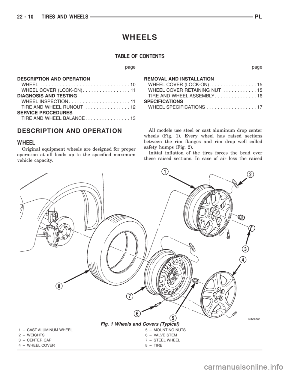
vehicle capacity.All models use steel or cast aluminum drop center
wheels (Fig. 1). Every wheel has raised sections
between the rim flanges and rim drop well called
safety humps (Fig. 2).
Initial inflation of the tires forces the bead over
these raised sections. In case of air loss the raised
Fig. 1 Wheels and Covers (Typical)
1 ± CAST ALUMINUM WHEEL
2 ± WEIGHTS
3 ± CENTER CAP
4 ± WHEEL COVER5 ± MOUNTING NUTS
6 ± VALVE STEM
7 ± STEEL WHEEL
8 ± TIRE
22 - 10 TIRES AND WHEELSPL