2000 DODGE NEON Torque clutch solenoid
[x] Cancel search: Torque clutch solenoidPage 176 of 1285
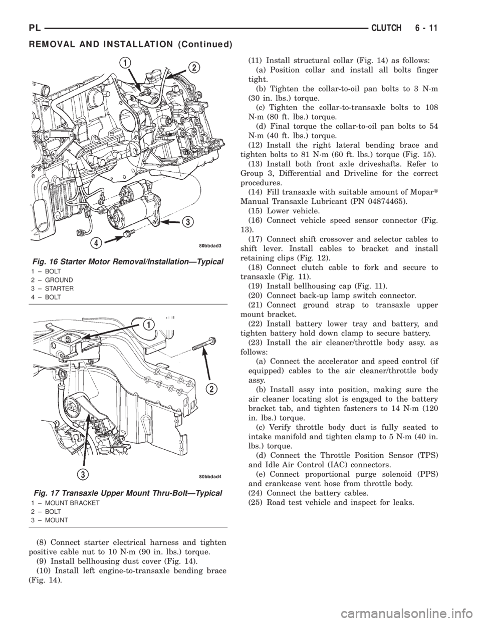
(8) Connect starter electrical harness and tighten
positive cable nut to 10 N´m (90 in. lbs.) torque.
(9) Install bellhousing dust cover (Fig. 14).
(10) Install left engine-to-transaxle bending brace
(Fig. 14).(11) Install structural collar (Fig. 14) as follows:
(a) Position collar and install all bolts finger
tight.
(b) Tighten the collar-to-oil pan bolts to 3 N´m
(30 in. lbs.) torque.
(c) Tighten the collar-to-transaxle bolts to 108
N´m (80 ft. lbs.) torque.
(d) Final torque the collar-to-oil pan bolts to 54
N´m (40 ft. lbs.) torque.
(12) Install the right lateral bending brace and
tighten bolts to 81 N´m (60 ft. lbs.) torque (Fig. 15).
(13) Install both front axle driveshafts. Refer to
Group 3, Differential and Driveline for the correct
procedures.
(14) Fill transaxle with suitable amount of Mopart
Manual Transaxle Lubricant (PN 04874465).
(15) Lower vehicle.
(16) Connect vehicle speed sensor connector (Fig.
13).
(17) Connect shift crossover and selector cables to
shift lever. Install cables to bracket and install
retaining clips (Fig. 12).
(18) Connect clutch cable to fork and secure to
transaxle (Fig. 11).
(19) Install bellhousing cap (Fig. 11).
(20) Connect back-up lamp switch connector.
(21) Connect ground strap to transaxle upper
mount bracket.
(22) Install battery lower tray and battery, and
tighten battery hold down clamp to secure battery.
(23) Install the air cleaner/throttle body assy. as
follows:
(a) Connect the accelerator and speed control (if
equipped) cables to the air cleaner/throttle body
assy.
(b) Install assy into position, making sure the
air cleaner locating slot is engaged to the battery
bracket tab, and tighten fasteners to 14 N´m (120
in. lbs.) torque.
(c) Verify throttle body duct is fully seated to
intake manifold and tighten clamp to 5 N´m (40 in.
lbs.) torque.
(d) Connect the Throttle Position Sensor (TPS)
and Idle Air Control (IAC) connectors.
(e) Connect proportional purge solenoid (PPS)
and crankcase vent hose from throttle body.
(24) Connect the battery cables.
(25) Road test vehicle and inspect for leaks.
Fig. 16 Starter Motor Removal/InstallationÐTypical
1 ± BOLT
2 ± GROUND
3±STARTER
4 ± BOLT
Fig. 17 Transaxle Upper Mount Thru-BoltÐTypical
1 ± MOUNT BRACKET
2 ± BOLT
3 ± MOUNT
PLCLUTCH 6 - 11
REMOVAL AND INSTALLATION (Continued)
Page 222 of 1285
STARTING SYSTEMS
TABLE OF CONTENTS
page page
GENERAL INFORMATION
INTRODUCTION..........................1
SUPPLY CIRCUIT AND CONTROL CIRCUIT.....1
DESCRIPTION AND OPERATION
STARTER MOTOR.........................1
DIAGNOSIS AND TESTING
CONTROL CIRCUIT........................2
FEED CIRCUIT RESISTANCE................3
FEED CIRCUIT...........................5STARTING SYSTEM.......................6
REMOVAL AND INSTALLATION
SAFETY SWITCHES.......................8
STARTER MOTOR.........................8
STARTER RELAY.........................8
SPECIFICATIONS
STARTER MOTOR.........................9
TORQUE................................9
GENERAL INFORMATION
INTRODUCTION
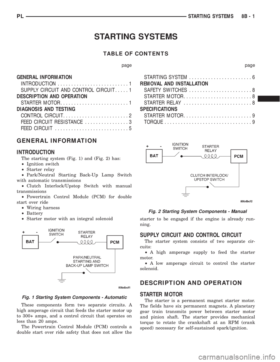
The starting system (Fig. 1) and (Fig. 2) has:
²Ignition switch
²Starter relay
²Park/Neutral Starting Back-Up Lamp Switch
with automatic transmissions
²Clutch Interlock/Upstop Switch with manual
transmissions
²Powertrain Control Module (PCM) for double
start over ride
²Wiring harness
²Battery
²Starter motor with an integral solenoid
These components form two separate circuits. A
high amperage circuit that feeds the starter motor up
to 300+ amps, and a control circuit that operates on
less than 20 amps.
The Powertrain Control Module (PCM) controls a
double start over ride safety that does not allow thestarter to be engaged if the engine is already run-
ning.
SUPPLY CIRCUIT AND CONTROL CIRCUIT
The starter system consists of two separate cir-
cuits:
²A high amperage supply to feed the starter
motor.
²A low amperage circuit to control the starter
solenoid.
DESCRIPTION AND OPERATION
STARTER MOTOR
The starter is a permanent magnet starter motor.
The fields have six permanent magnets. A planetary
gear train transmits power between starter motor
and pinion shaft. The starter provides mechanical
torque to rotate the crankshaft at an RPM (crank
speed) necessary for self-sustained spark/ignition.Fig. 1 Starting System Components - Automatic
Fig. 2 Starting System Components - Manual
PLSTARTING SYSTEMS 8B - 1
Page 228 of 1285
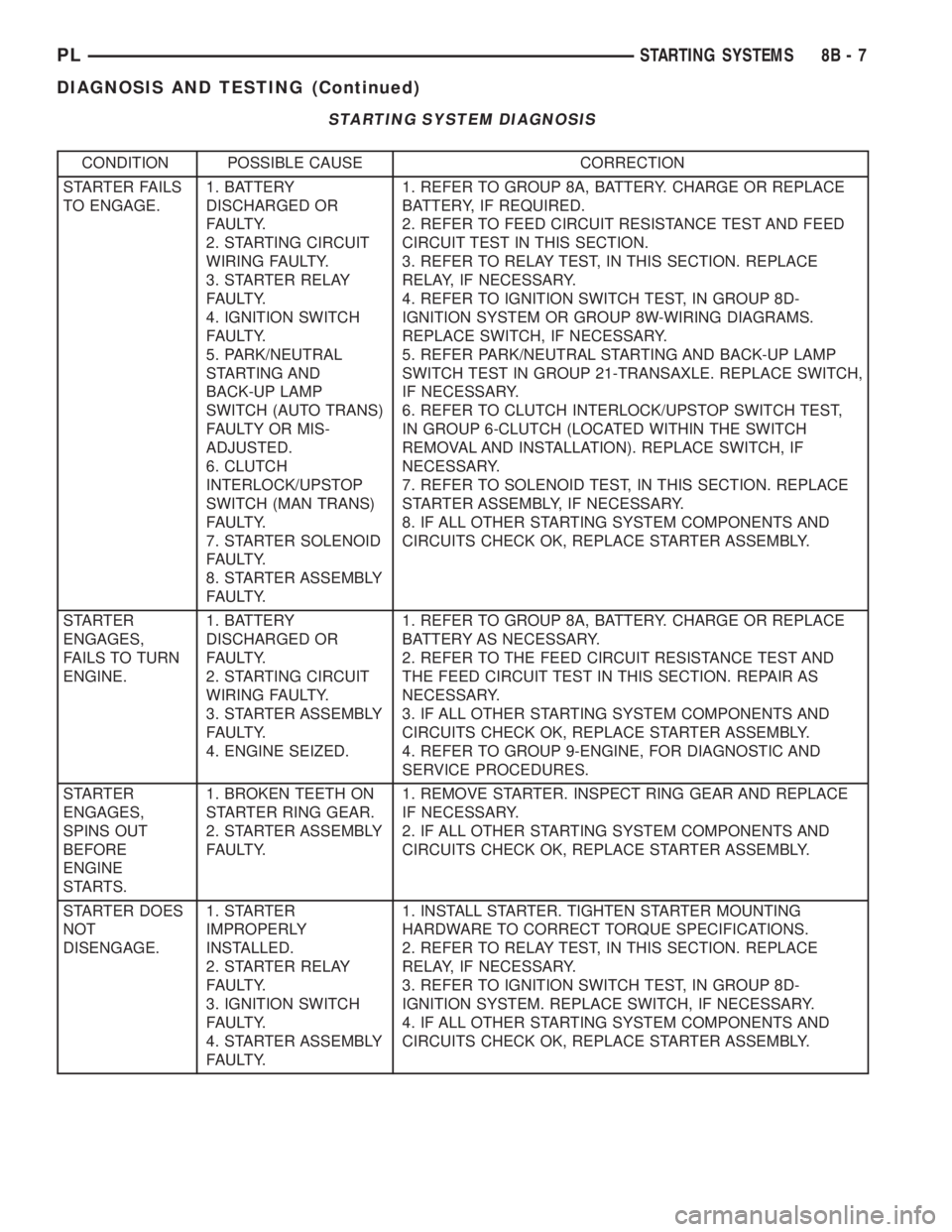
STARTING SYSTEM DIAGNOSIS
CONDITION POSSIBLE CAUSE CORRECTION
STARTER FAILS
TO ENGAGE.1. BATTERY
DISCHARGED OR
FAULTY.
2. STARTING CIRCUIT
WIRING FAULTY.
3. STARTER RELAY
FAULTY.
4. IGNITION SWITCH
FAULTY.
5. PARK/NEUTRAL
STARTING AND
BACK-UP LAMP
SWITCH (AUTO TRANS)
FAULTY OR MIS-
ADJUSTED.
6. CLUTCH
INTERLOCK/UPSTOP
SWITCH (MAN TRANS)
FAULTY.
7. STARTER SOLENOID
FAULTY.
8. STARTER ASSEMBLY
FAULTY.1. REFER TO GROUP 8A, BATTERY. CHARGE OR REPLACE
BATTERY, IF REQUIRED.
2. REFER TO FEED CIRCUIT RESISTANCE TEST AND FEED
CIRCUIT TEST IN THIS SECTION.
3. REFER TO RELAY TEST, IN THIS SECTION. REPLACE
RELAY, IF NECESSARY.
4. REFER TO IGNITION SWITCH TEST, IN GROUP 8D-
IGNITION SYSTEM OR GROUP 8W-WIRING DIAGRAMS.
REPLACE SWITCH, IF NECESSARY.
5. REFER PARK/NEUTRAL STARTING AND BACK-UP LAMP
SWITCH TEST IN GROUP 21-TRANSAXLE. REPLACE SWITCH,
IF NECESSARY.
6. REFER TO CLUTCH INTERLOCK/UPSTOP SWITCH TEST,
IN GROUP 6-CLUTCH (LOCATED WITHIN THE SWITCH
REMOVAL AND INSTALLATION). REPLACE SWITCH, IF
NECESSARY.
7. REFER TO SOLENOID TEST, IN THIS SECTION. REPLACE
STARTER ASSEMBLY, IF NECESSARY.
8. IF ALL OTHER STARTING SYSTEM COMPONENTS AND
CIRCUITS CHECK OK, REPLACE STARTER ASSEMBLY.
STARTER
ENGAGES,
FAILS TO TURN
ENGINE.1. BATTERY
DISCHARGED OR
FAULTY.
2. STARTING CIRCUIT
WIRING FAULTY.
3. STARTER ASSEMBLY
FAULTY.
4. ENGINE SEIZED.1. REFER TO GROUP 8A, BATTERY. CHARGE OR REPLACE
BATTERY AS NECESSARY.
2. REFER TO THE FEED CIRCUIT RESISTANCE TEST AND
THE FEED CIRCUIT TEST IN THIS SECTION. REPAIR AS
NECESSARY.
3. IF ALL OTHER STARTING SYSTEM COMPONENTS AND
CIRCUITS CHECK OK, REPLACE STARTER ASSEMBLY.
4. REFER TO GROUP 9-ENGINE, FOR DIAGNOSTIC AND
SERVICE PROCEDURES.
STARTER
ENGAGES,
SPINS OUT
BEFORE
ENGINE
STARTS.1. BROKEN TEETH ON
STARTER RING GEAR.
2. STARTER ASSEMBLY
FAULTY.1. REMOVE STARTER. INSPECT RING GEAR AND REPLACE
IF NECESSARY.
2. IF ALL OTHER STARTING SYSTEM COMPONENTS AND
CIRCUITS CHECK OK, REPLACE STARTER ASSEMBLY.
STARTER DOES
NOT
DISENGAGE.1. STARTER
IMPROPERLY
INSTALLED.
2. STARTER RELAY
FAULTY.
3. IGNITION SWITCH
FAULTY.
4. STARTER ASSEMBLY
FAULTY.1. INSTALL STARTER. TIGHTEN STARTER MOUNTING
HARDWARE TO CORRECT TORQUE SPECIFICATIONS.
2. REFER TO RELAY TEST, IN THIS SECTION. REPLACE
RELAY, IF NECESSARY.
3. REFER TO IGNITION SWITCH TEST, IN GROUP 8D-
IGNITION SYSTEM. REPLACE SWITCH, IF NECESSARY.
4. IF ALL OTHER STARTING SYSTEM COMPONENTS AND
CIRCUITS CHECK OK, REPLACE STARTER ASSEMBLY.
PLSTARTING SYSTEMS 8B - 7
DIAGNOSIS AND TESTING (Continued)
Page 229 of 1285
REMOVAL AND INSTALLATION
SAFETY SWITCHES
For Removal and Installation of:
²Clutch Interlock/Upstop Switch, refer to
Removal and Installation in Group 6-Clutch.
²Park/Neutral Starting and Back-Up Lamp
Switch, refer to Removal and Installation in Group
21-Transaxle.
STARTER MOTOR
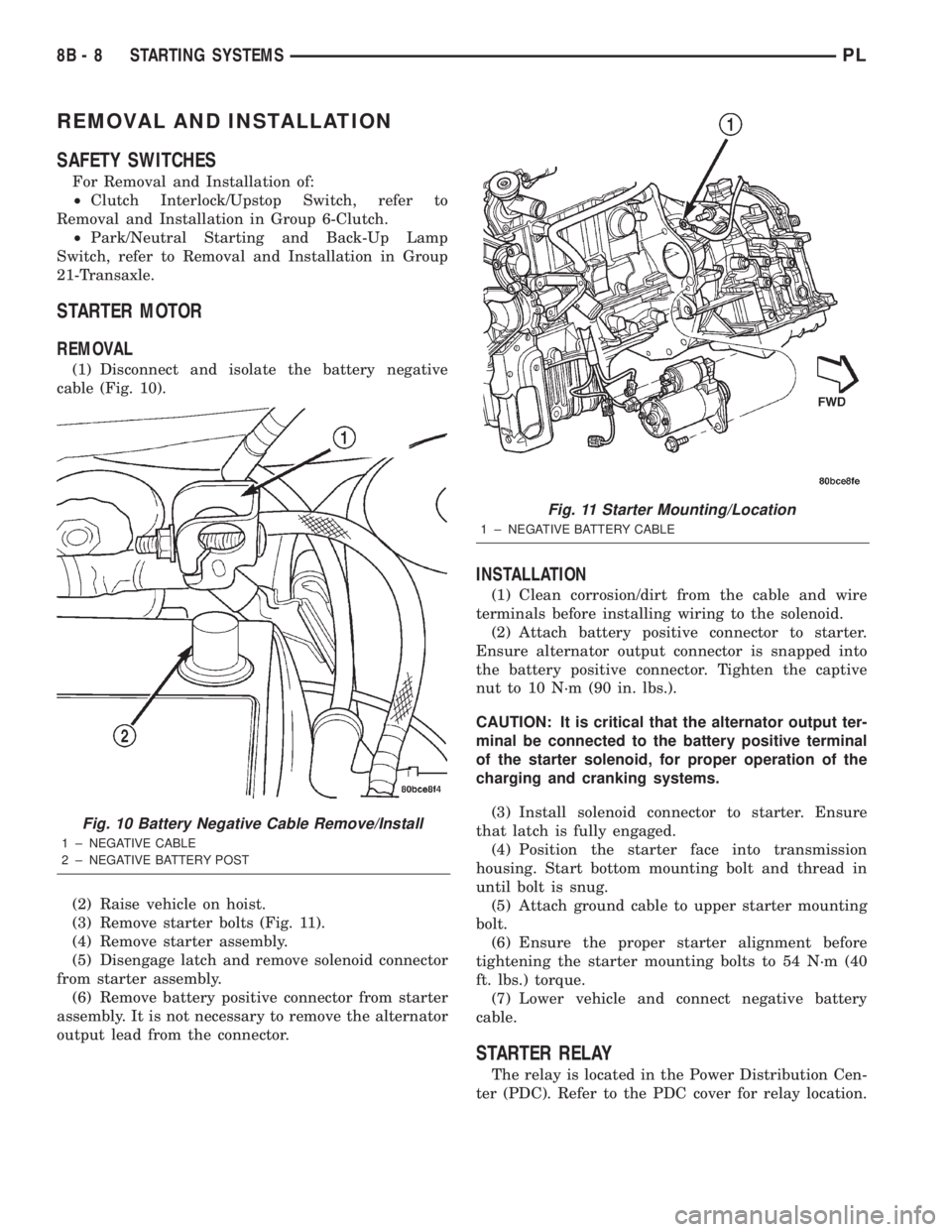
REMOVAL
(1) Disconnect and isolate the battery negative
cable (Fig. 10).
(2) Raise vehicle on hoist.
(3) Remove starter bolts (Fig. 11).
(4) Remove starter assembly.
(5) Disengage latch and remove solenoid connector
from starter assembly.
(6) Remove battery positive connector from starter
assembly. It is not necessary to remove the alternator
output lead from the connector.
INSTALLATION
(1) Clean corrosion/dirt from the cable and wire
terminals before installing wiring to the solenoid.
(2) Attach battery positive connector to starter.
Ensure alternator output connector is snapped into
the battery positive connector. Tighten the captive
nut to 10 N´m (90 in. lbs.).
CAUTION: It is critical that the alternator output ter-
minal be connected to the battery positive terminal
of the starter solenoid, for proper operation of the
charging and cranking systems.
(3) Install solenoid connector to starter. Ensure
that latch is fully engaged.
(4) Position the starter face into transmission
housing. Start bottom mounting bolt and thread in
until bolt is snug.
(5) Attach ground cable to upper starter mounting
bolt.
(6) Ensure the proper starter alignment before
tightening the starter mounting bolts to 54 N´m (40
ft. lbs.) torque.
(7) Lower vehicle and connect negative battery
cable.
STARTER RELAY
The relay is located in the Power Distribution Cen-
ter (PDC). Refer to the PDC cover for relay location.
Fig. 10 Battery Negative Cable Remove/Install
1 ± NEGATIVE CABLE
2 ± NEGATIVE BATTERY POST
Fig. 11 Starter Mounting/Location
1 ± NEGATIVE BATTERY CABLE
8B - 8 STARTING SYSTEMSPL
Page 411 of 1285
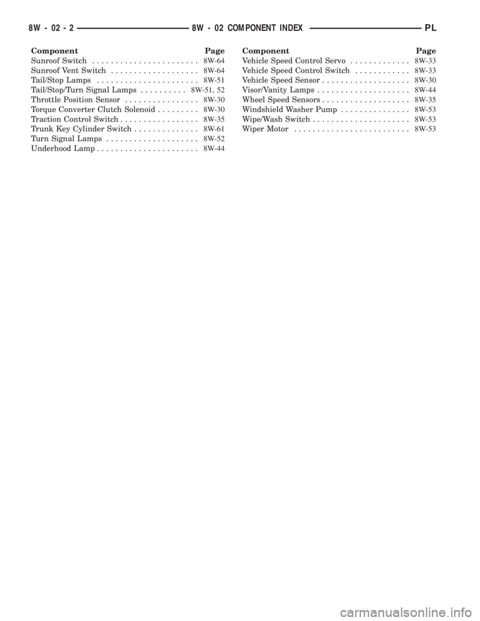
Component Page
Sunroof Switch.......................8W-64
Sunroof Vent Switch...................8W-64
Tail/Stop Lamps......................8W-51
Tail/Stop/Turn Signal Lamps..........8W-51, 52
Throttle Position Sensor................8W-30
Torque Converter Clutch Solenoid.........8W-30
Traction Control Switch.................8W-35
Trunk Key Cylinder Switch..............8W-61
Turn Signal Lamps....................8W-52
Underhood Lamp......................8W-44Component Page
Vehicle Speed Control Servo.............8W-33
Vehicle Speed Control Switch............8W-33
Vehicle Speed Sensor...................8W-30
Visor/Vanity Lamps....................8W-44
Wheel Speed Sensors...................8W-35
Windshield Washer Pump...............8W-53
Wipe/Wash Switch.....................8W-53
Wiper Motor.........................8W-53
8W - 02 - 2 8W - 02 COMPONENT INDEXPL
Page 432 of 1285
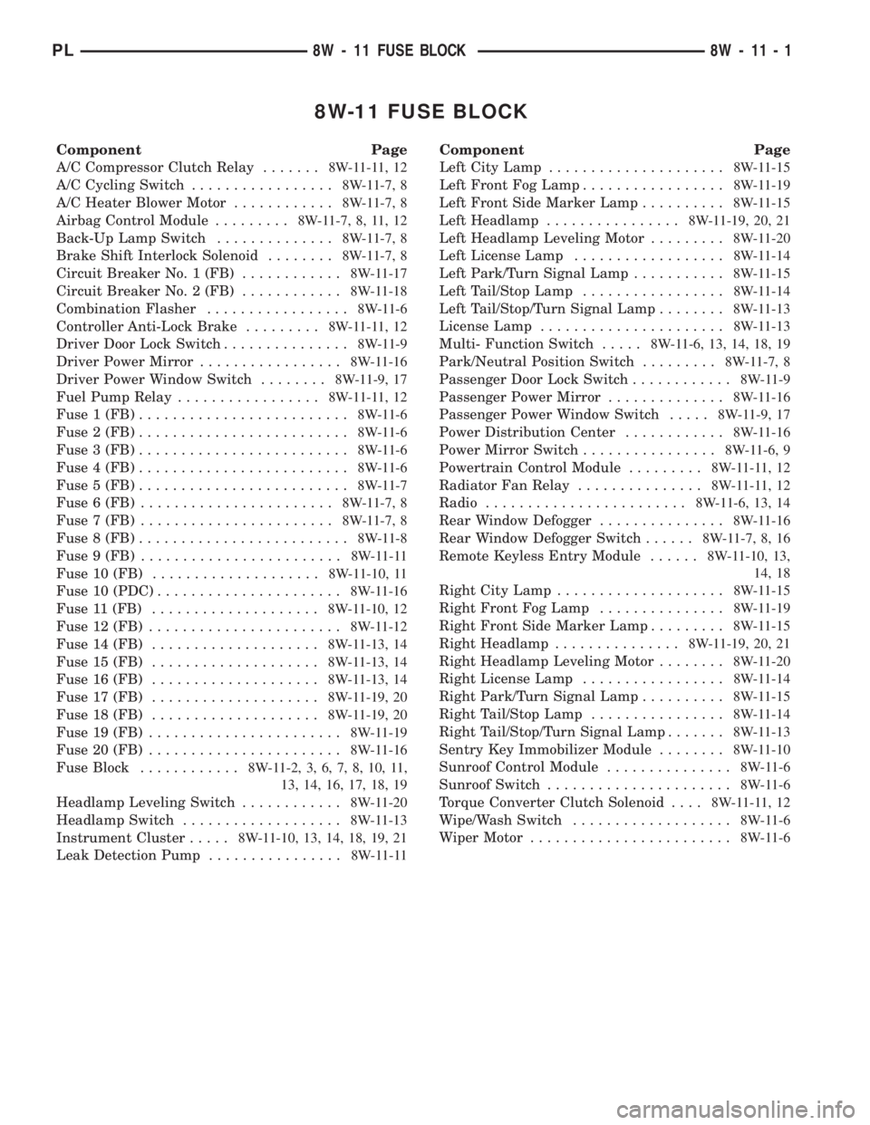
8W-11 FUSE BLOCK
Component Page
A/C Compressor Clutch Relay.......8W-11-11, 12
A/C Cycling Switch.................8W-11-7, 8
A/C Heater Blower Motor............8W-11-7, 8
Airbag Control Module.........8W-11-7, 8, 11, 12
Back-Up Lamp Switch..............8W-11-7, 8
Brake Shift Interlock Solenoid........8W-11-7, 8
Circuit Breaker No. 1 (FB)............8W-11-17
Circuit Breaker No. 2 (FB)............8W-11-18
Combination Flasher.................8W-11-6
Controller Anti-Lock Brake.........8W-11-11, 12
Driver Door Lock Switch...............8W-11-9
Driver Power Mirror.................8W-11-16
Driver Power Window Switch........8W-11-9, 17
Fuel Pump Relay.................8W-11-11, 12
Fuse 1 (FB).........................8W-11-6
Fuse 2 (FB).........................8W-11-6
Fuse 3 (FB).........................8W-11-6
Fuse 4 (FB).........................8W-11-6
Fuse 5 (FB).........................8W-11-7
Fuse 6 (FB).......................8W-11-7, 8
Fuse 7 (FB).......................8W-11-7, 8
Fuse 8 (FB).........................8W-11-8
Fuse 9 (FB)........................8W-11-11
Fuse 10 (FB)....................8W-11-10, 11
Fuse 10 (PDC)......................8W-11-16
Fuse 11 (FB)....................8W-11-10, 12
Fuse 12 (FB).......................8W-11-12
Fuse 14 (FB)....................8W-11-13, 14
Fuse 15 (FB)....................8W-11-13, 14
Fuse 16 (FB)....................8W-11-13, 14
Fuse 17 (FB)....................8W-11-19, 20
Fuse 18 (FB)....................8W-11-19, 20
Fuse 19 (FB).......................8W-11-19
Fuse 20 (FB).......................8W-11-16
Fuse Block............8W-11-2, 3, 6, 7, 8, 10, 11,
13, 14, 16, 17, 18, 19
Headlamp Leveling Switch............8W-11-20
Headlamp Switch...................8W-11-13
Instrument Cluster.....8W-11-10, 13, 14, 18, 19, 21
Leak Detection Pump................8W-11-11Component Page
Left City Lamp.....................8W-11-15
Left Front Fog Lamp.................8W-11-19
Left Front Side Marker Lamp..........8W-11-15
Left Headlamp................8W-11-19, 20, 21
Left Headlamp Leveling Motor.........8W-11-20
Left License Lamp..................8W-11-14
Left Park/Turn Signal Lamp...........8W-11-15
Left Tail/Stop Lamp.................8W-11-14
Left Tail/Stop/Turn Signal Lamp........8W-11-13
License Lamp......................8W-11-13
Multi- Function Switch.....8W-11-6, 13, 14, 18, 19
Park/Neutral Position Switch.........8W-11-7, 8
Passenger Door Lock Switch............8W-11-9
Passenger Power Mirror..............8W-11-16
Passenger Power Window Switch.....8W-11-9, 17
Power Distribution Center............8W-11-16
Power Mirror Switch................8W-11-6, 9
Powertrain Control Module.........8W-11-11, 12
Radiator Fan Relay...............8W-11-11, 12
Radio........................8W-11-6, 13, 14
Rear Window Defogger...............8W-11-16
Rear Window Defogger Switch......8W-11-7, 8, 16
Remote Keyless Entry Module......8W-11-10, 13,
14, 18
Right City Lamp....................8W-11-15
Right Front Fog Lamp...............8W-11-19
Right Front Side Marker Lamp.........8W-11-15
Right Headlamp...............8W-11-19, 20, 21
Right Headlamp Leveling Motor........8W-11-20
Right License Lamp.................8W-11-14
Right Park/Turn Signal Lamp..........8W-11-15
Right Tail/Stop Lamp................8W-11-14
Right Tail/Stop/Turn Signal Lamp.......8W-11-13
Sentry Key Immobilizer Module........8W-11-10
Sunroof Control Module...............8W-11-6
Sunroof Switch......................8W-11-6
Torque Converter Clutch Solenoid....8W-11-11, 12
Wipe/Wash Switch...................8W-11-6
Wiper Motor........................8W-11-6
PL8W - 11 FUSE BLOCK 8W - 11 - 1
Page 442 of 1285
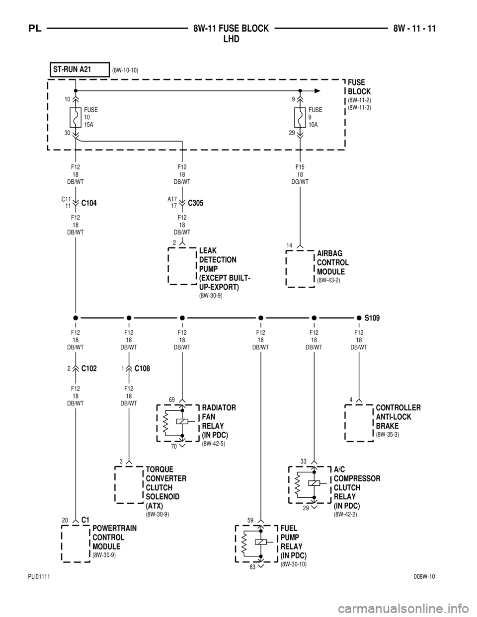
9FUSE10A
29
BLOCK
FUSE9
ST-RUN A21
10
30
15A
FUSE
10
F12
18
DB/WTF12
18
DB/WTF15
18
DG/WT
14
C30517C10411 C11 A17
2
UP-EXPORT) (EXCEPT BUILT-
PUMP
DETECTION
LEAK
AIRBAG
CONTROL
MODULE
F12
18
DB/WTF12
18
DB/WT
3
C120
4
59
63
33
29
69
70
2C1021C108
F12
18
DB/WTF12
18
DB/WTF12
18
DB/WTF12
18
DB/WTF12
18
DB/WTF12
18
DB/WT
CONTROLLER
ANTI-LOCK
BRAKE
FUEL
PUMP
RELAY RADIATOR
FAN
RELAY
POWERTRAIN
CONTROL
MODULERELAY CLUTCH
COMPRESSOR
A/C
(ATX) SOLENOID
CLUTCH
CONVERTER
TORQUES109
F12
18
DB/WTF12
18
DB/WT
(IN PDC)
(IN PDC)(IN PDC)
(8W-11-2)
(8W-11-3) (8W-10-10)
(8W-30-9)(8W-43-2)
(8W-35-3)
(8W-30-10) (8W-42-5)
(8W-30-9)(8W-42-2) (8W-30-9)
PL8W-11 FUSE BLOCK
LHD8W - 11 - 11
PLI01111008W-10
Page 443 of 1285
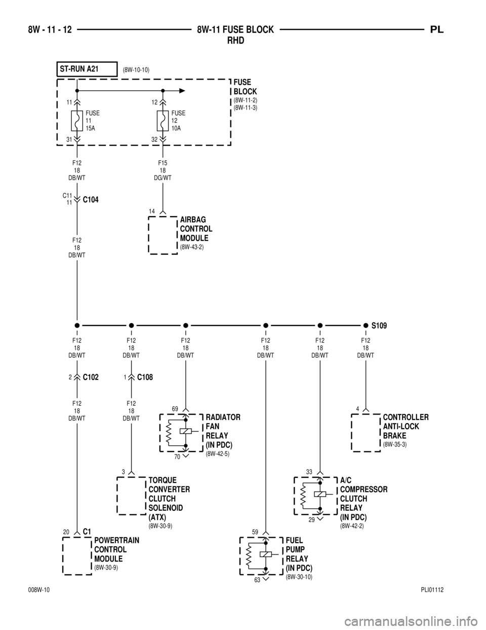
11FUSE15A 10A
FUSE
12
3132
BLOCK FUSE
1112
ST-RUN A21
F15
18
DG/WT
14
AIRBAG
CONTROL
MODULE
11C104C11F12
18
DB/WT
F12
18
DB/WT
TORQUE
CONVERTER
CLUTCH
SOLENOID
(ATX)A/C
COMPRESSOR
CLUTCH
RELAY
MODULE CONTROL
POWERTRAINRELAY FAN
RADIATOR
RELAY PUMP
FUELBRAKE ANTI-LOCK
CONTROLLER
DB/WT18 F12DB/WT18 F12DB/WT18 F12DB/WT18 F12DB/WT18 F12DB/WT18 F12
C1081C1022
70
69
29
33
63
59
4
20C1
3
F12
18
DB/WTF12
18
DB/WT
S109
(IN PDC)
(IN PDC) (IN PDC)
(8W-11-2)
(8W-11-3) (8W-10-10)
(8W-43-2)
(8W-30-9) (8W-42-2)
(8W-30-9)(8W-42-5)
(8W-30-10)(8W-35-3)
8W - 11 - 12 8W-11 FUSE BLOCK
RHDPL
008W-10PLI01112