2000 DODGE NEON Torque clutch solenoid
[x] Cancel search: Torque clutch solenoidPage 977 of 1285
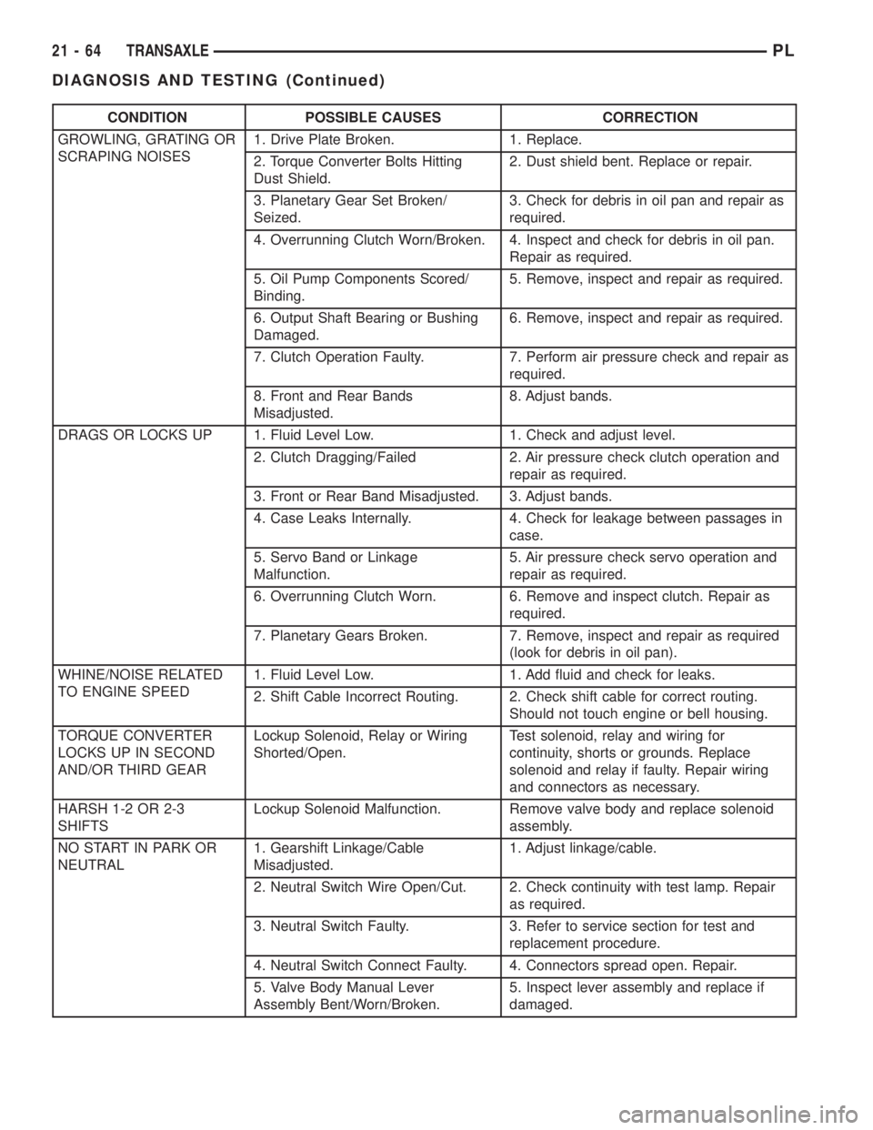
CONDITION POSSIBLE CAUSES CORRECTION
GROWLING, GRATING OR
SCRAPING NOISES1. Drive Plate Broken. 1. Replace.
2. Torque Converter Bolts Hitting
Dust Shield.2. Dust shield bent. Replace or repair.
3. Planetary Gear Set Broken/
Seized.3. Check for debris in oil pan and repair as
required.
4. Overrunning Clutch Worn/Broken. 4. Inspect and check for debris in oil pan.
Repair as required.
5. Oil Pump Components Scored/
Binding.5. Remove, inspect and repair as required.
6. Output Shaft Bearing or Bushing
Damaged.6. Remove, inspect and repair as required.
7. Clutch Operation Faulty. 7. Perform air pressure check and repair as
required.
8. Front and Rear Bands
Misadjusted.8. Adjust bands.
DRAGS OR LOCKS UP 1. Fluid Level Low. 1. Check and adjust level.
2. Clutch Dragging/Failed 2. Air pressure check clutch operation and
repair as required.
3. Front or Rear Band Misadjusted. 3. Adjust bands.
4. Case Leaks Internally. 4. Check for leakage between passages in
case.
5. Servo Band or Linkage
Malfunction.5. Air pressure check servo operation and
repair as required.
6. Overrunning Clutch Worn. 6. Remove and inspect clutch. Repair as
required.
7. Planetary Gears Broken. 7. Remove, inspect and repair as required
(look for debris in oil pan).
WHINE/NOISE RELATED
TO ENGINE SPEED1. Fluid Level Low. 1. Add fluid and check for leaks.
2. Shift Cable Incorrect Routing. 2. Check shift cable for correct routing.
Should not touch engine or bell housing.
TORQUE CONVERTER
LOCKS UP IN SECOND
AND/OR THIRD GEARLockup Solenoid, Relay or Wiring
Shorted/Open.Test solenoid, relay and wiring for
continuity, shorts or grounds. Replace
solenoid and relay if faulty. Repair wiring
and connectors as necessary.
HARSH 1-2 OR 2-3
SHIFTSLockup Solenoid Malfunction. Remove valve body and replace solenoid
assembly.
NO START IN PARK OR
NEUTRAL1. Gearshift Linkage/Cable
Misadjusted.1. Adjust linkage/cable.
2. Neutral Switch Wire Open/Cut. 2. Check continuity with test lamp. Repair
as required.
3. Neutral Switch Faulty. 3. Refer to service section for test and
replacement procedure.
4. Neutral Switch Connect Faulty. 4. Connectors spread open. Repair.
5. Valve Body Manual Lever
Assembly Bent/Worn/Broken.5. Inspect lever assembly and replace if
damaged.
21 - 64 TRANSAXLEPL
DIAGNOSIS AND TESTING (Continued)
Page 997 of 1285
PARK/NEUTRAL STARTING AND BACK-UP
LAMP SWITCH
TEST
The park/neutral starting switch is the center ter-
minal of the three terminal switch. It provides
ground for the starter solenoid circuit through the
selector lever in PARK and NEUTRAL positions only.
(1) To test switch, remove wiring connector from
switch and test for continuity between center pin of
switch and transaxle case. Continuity should exist
only when transaxle is in PARK or NEUTRAL.
(2) Check gearshift cable adjustment before replac-
ing a switch that tests bad.
REMOVAL
(1) Unscrew switch from transaxle case allowing
fluid to drain into a container. Move selector lever to
PARK, then to NEUTRAL position, and inspect to see
the switch operating lever fingers are centered in
switch opening.
INSTALLATION
(1) Screw the switch with a new seal into tran-
saxle case and tighten to 33 N´m (24 ft. lbs.). Retest
switch with the test lamp.
(2) Add fluid to transaxle to bring up to proper
level.
(3) The back-up lamp switch circuit is through the
two outside terminals of the three terminal switch.
(4) To test switch, remove wiring connector from
switch and test for continuity between the two out-
side pins.
(5) Continuity should exist only with transaxle in
REVERSE position.
(6) No continuity should exist from either pin to
the case.
TRANSAXLE AND TORQUE CONVERTER
REMOVAL
(1) Raise hood.
(2) Disconnect both battery cables, remove battery
hold down clamp and bolt, and remove battery.
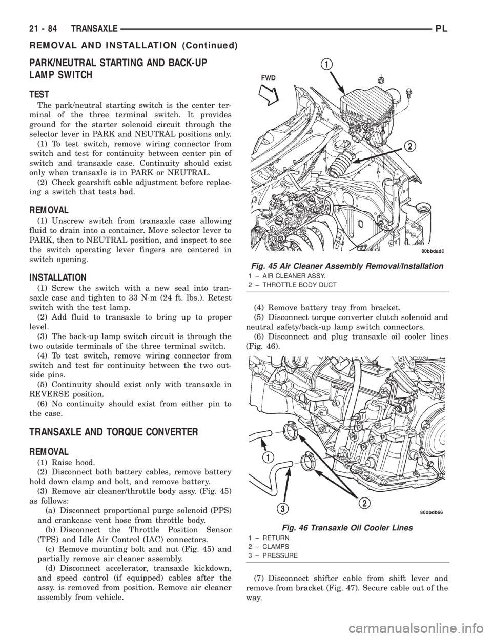
(3) Remove air cleaner/throttle body assy. (Fig. 45)
as follows:
(a) Disconnect proportional purge solenoid (PPS)
and crankcase vent hose from throttle body.
(b) Disconnect the Throttle Position Sensor
(TPS) and Idle Air Control (IAC) connectors.
(c) Remove mounting bolt and nut (Fig. 45) and
partially remove air cleaner assembly.
(d) Disconnect accelerator, transaxle kickdown,
and speed control (if equipped) cables after the
assy. is removed from position. Remove air cleaner
assembly from vehicle.(4) Remove battery tray from bracket.
(5) Disconnect torque converter clutch solenoid and
neutral safety/back-up lamp switch connectors.
(6) Disconnect and plug transaxle oil cooler lines
(Fig. 46).
(7) Disconnect shifter cable from shift lever and
remove from bracket (Fig. 47). Secure cable out of the
way.
Fig. 45 Air Cleaner Assembly Removal/Installation
1 ± AIR CLEANER ASSY.
2 ± THROTTLE BODY DUCT
Fig. 46 Transaxle Oil Cooler Lines
1 ± RETURN
2 ± CLAMPS
3 ± PRESSURE
21 - 84 TRANSAXLEPL
REMOVAL AND INSTALLATION (Continued)
Page 1001 of 1285
(c) Tighten the collar-to-transaxle bolts to 108
N´m (80 ft. lbs.) torque.
(d) Final torque the collar-to-oil pan bolts to 54
N´m (40 ft. lbs.) torque.
(11) Install both front axle driveshafts. Refer to
Group 3, Differential and Driveline for the correct
procedures.
(12) Connect vehicle speed sensor connector (Fig.
50).
(13) Install right lateral bending brace and tighten
bolts to 81 N´m (60 ft. lbs.) torque.
(14) Lower vehicle.
(15) Connect transaxle cooler lines and tighten
clamps (Fig. 46).
(16) Connect torque converter clutch solenoid and
neutral safety/back-up lamp switch connectors.
(17) Install transaxle dipstick tube.
(18) Install gear shift cable to bracket and connect
to shift lever (Fig. 47).
(19) Install transaxle kickdown cable to bracket
and lever as shown in (Fig. 48).
(20) Install battery lower tray and battery, and
tighten battery hold down clamp to secure battery.
(21) Install the air cleaner/throttle body assy. as
follows:
(a) Connect the accelerator, transaxle kickdown,
and speed control (if equipped) cables to the air
cleaner/throttle body assy.
(b) Install assy into position and tighten fasten-
ers to 14 N´m (120 in. lbs.) torque.
(c) Connect the Throttle Position Sensor (TPS)
and Idle Air Control (IAC) connectors.
(d) Connect proportional purge solenoid (PPS)
and crankcase vent hose from throttle body.
(22) Fill transaxle with a suitable amount of
ATF+4.
(23) Road test vehicle.
(24) Check for leaks, inspect fluid level, and adjust
as necessary.
PUMP OIL SEAL
The pump oil seal can be replaced without remov-
ing the pump and reaction shaft support assembly
from the transaxle case.
REMOVAL
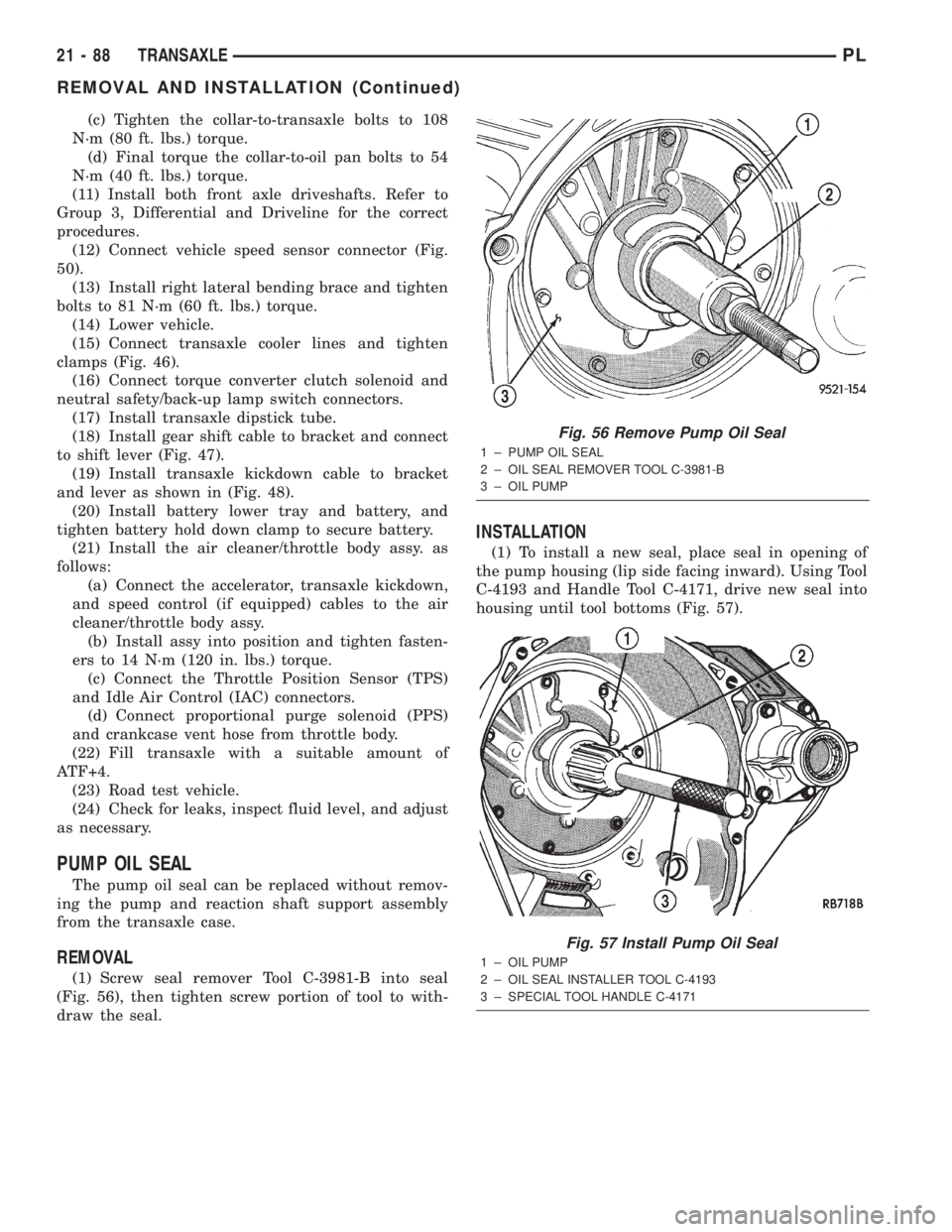
(1) Screw seal remover Tool C-3981-B into seal
(Fig. 56), then tighten screw portion of tool to with-
draw the seal.
INSTALLATION
(1) To install a new seal, place seal in opening of
the pump housing (lip side facing inward). Using Tool
C-4193 and Handle Tool C-4171, drive new seal into
housing until tool bottoms (Fig. 57).
Fig. 56 Remove Pump Oil Seal
1 ± PUMP OIL SEAL
2 ± OIL SEAL REMOVER TOOL C-3981-B
3 ± OIL PUMP
Fig. 57 Install Pump Oil Seal
1 ± OIL PUMP
2 ± OIL SEAL INSTALLER TOOL C-4193
3 ± SPECIAL TOOL HANDLE C-4171
21 - 88 TRANSAXLEPL
REMOVAL AND INSTALLATION (Continued)
Page 1015 of 1285
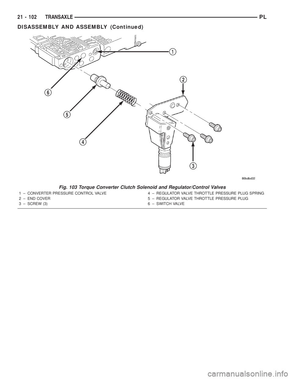
Fig. 103 Torque Converter Clutch Solenoid and Regulator/Control Valves
1 ± CONVERTER PRESSURE CONTROL VALVE
2 ± END COVER
3 ± SCREW (3)4 ± REGULATOR VALVE THROTTLE PRESSURE PLUG SPRING
5 ± REGULATOR VALVE THROTTLE PRESSURE PLUG
6 ± SWITCH VALVE
21 - 102 TRANSAXLEPL
DISASSEMBLY AND ASSEMBLY (Continued)
Page 1016 of 1285
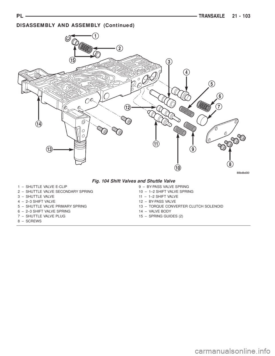
Fig. 104 Shift Valves and Shuttle Valve
1 ± SHUTTLE VALVE E-CLIP
2 ± SHUTTLE VALVE SECONDARY SPRING
3 ± SHUTTLE VALVE
4 ± 2±3 SHIFT VALVE
5 ± SHUTTLE VALVE PRIMARY SPRING
6 ± 2±3 SHIFT VALVE SPRING
7 ± SHUTTLE VALVE PLUG
8 ± SCREWS9 ± BY-PASS VALVE SPRING
10 ± 1±2 SHIFT VALVE SPRING
11 ± 1±2 SHIFT VALVE
1 2 ± B Y- PA S S VA LV E
13 ± TORQUE CONVERTER CLUTCH SOLENOID
14 ± VALVE BODY
15 ± SPRING GUIDES (2)
PLTRANSAXLE 21 - 103
DISASSEMBLY AND ASSEMBLY (Continued)
Page 1098 of 1285
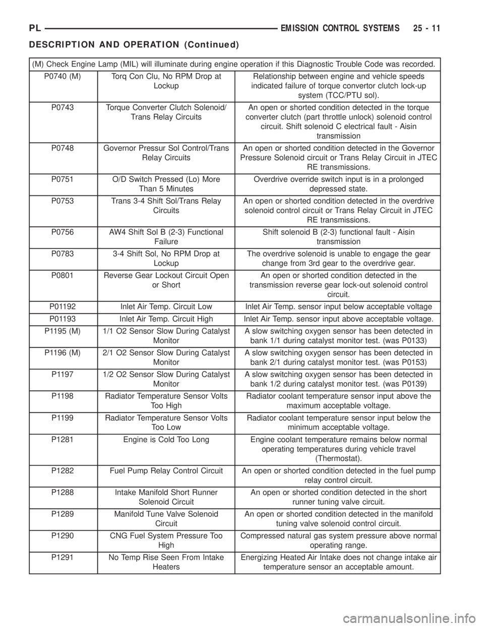
(M) Check Engine Lamp (MIL) will illuminate during engine operation if this Diagnostic Trouble Code was recorded.
P0740 (M) Torq Con Clu, No RPM Drop at
LockupRelationship between engine and vehicle speeds
indicated failure of torque convertor clutch lock-up
system (TCC/PTU sol).
P0743 Torque Converter Clutch Solenoid/
Trans Relay CircuitsAn open or shorted condition detected in the torque
converter clutch (part throttle unlock) solenoid control
circuit. Shift solenoid C electrical fault - Aisin
transmission
P0748 Governor Pressur Sol Control/Trans
Relay CircuitsAn open or shorted condition detected in the Governor
Pressure Solenoid circuit or Trans Relay Circuit in JTEC
RE transmissions.
P0751 O/D Switch Pressed (Lo) More
Than 5 MinutesOverdrive override switch input is in a prolonged
depressed state.
P0753 Trans 3-4 Shift Sol/Trans Relay
CircuitsAn open or shorted condition detected in the overdrive
solenoid control circuit or Trans Relay Circuit in JTEC
RE transmissions.
P0756 AW4 Shift Sol B (2-3) Functional
FailureShift solenoid B (2-3) functional fault - Aisin
transmission
P0783 3-4 Shift Sol, No RPM Drop at
LockupThe overdrive solenoid is unable to engage the gear
change from 3rd gear to the overdrive gear.
P0801 Reverse Gear Lockout Circuit Open
or ShortAn open or shorted condition detected in the
transmission reverse gear lock-out solenoid control
circuit.
P01192 Inlet Air Temp. Circuit Low Inlet Air Temp. sensor input below acceptable voltage
P01193 Inlet Air Temp. Circuit High Inlet Air Temp. sensor input above acceptable voltage.
P1195 (M) 1/1 O2 Sensor Slow During Catalyst
MonitorA slow switching oxygen sensor has been detected in
bank 1/1 during catalyst monitor test. (was P0133)
P1196 (M) 2/1 O2 Sensor Slow During Catalyst
MonitorA slow switching oxygen sensor has been detected in
bank 2/1 during catalyst monitor test. (was P0153)
P1197 1/2 O2 Sensor Slow During Catalyst
MonitorA slow switching oxygen sensor has been detected in
bank 1/2 during catalyst monitor test. (was P0139)
P1198 Radiator Temperature Sensor Volts
Too HighRadiator coolant temperature sensor input above the
maximum acceptable voltage.
P1199 Radiator Temperature Sensor Volts
Too LowRadiator coolant temperature sensor input below the
minimum acceptable voltage.
P1281 Engine is Cold Too Long Engine coolant temperature remains below normal
operating temperatures during vehicle travel
(Thermostat).
P1282 Fuel Pump Relay Control Circuit An open or shorted condition detected in the fuel pump
relay control circuit.
P1288 Intake Manifold Short Runner
Solenoid CircuitAn open or shorted condition detected in the short
runner tuning valve circuit.
P1289 Manifold Tune Valve Solenoid
CircuitAn open or shorted condition detected in the manifold
tuning valve solenoid control circuit.
P1290 CNG Fuel System Pressure Too
HighCompressed natural gas system pressure above normal
operating range.
P1291 No Temp Rise Seen From Intake
HeatersEnergizing Heated Air Intake does not change intake air
temperature sensor an acceptable amount.
PLEMISSION CONTROL SYSTEMS 25 - 11
DESCRIPTION AND OPERATION (Continued)
Page 1107 of 1285
NOTE: Comprehensive component monitors are
continuous. Therefore, enabling conditions do not
apply.
Input RationalityÐWhile input signals to the
PCM are constantly being monitored for electrical
opens and shorts, they are also tested for rationality.
This means that the input signal is compared against
other inputs and information to see if it makes sense
under the current conditions.
PCM sensor inputs that are checked for rationality
include:
²Manifold Absolute Pressure (MAP) Sensor
²Oxygen Sensor (O2S)
²Engine Coolant Temperature (ECT) Sensor
²Camshaft Position (CMP) Sensor
²Vehicle Speed Sensor
²Crankshaft Position (CKP) Sensor
²Intake Air Temperature (IAT) Sensor
²Throttle Position (TPS) Sensor
²Ambient/Battery Temperature Sensors
²Power Steering Switch
²Oxygen Sensor Heater
²Engine Controller
²Brake Switch
²Leak Detection Pump Switch
²P/N Switch
²Trans Controls
Output FunctionalityÐPCM outputs are tested
for functionality in addition to testing for opens and
shorts. When the PCM provides a voltage to an out-
put component, it can verify that the command was
carried out by monitoring specific input signals for
expected changes. For example, when the PCM com-
mands the Idle Air Control (IAC) Motor to a specific
position under certain operating conditions, it expects
to see a specific (target) idle speed (RPM). If it does
not, it stores a DTC.
PCM outputs monitored for functionality include:
²Fuel Injectors
²Ignition Coils
²Torque Converter Clutch Solenoid
²Idle Air Control
²Purge Solenoid
²EGR Solenoid
²LDP Solenoid
²Radiator Fan Control
²Trans Controls
OXYGEN SENSOR (O2S) MONITOR
DESCRIPTIONÐEffective control of exhaust
emissions is achieved by an oxygen feedback system.
The most important element of the feedback system
is the O2S. The O2S is located in the exhaust path.
Once it reaches operating temperature 300É to 350ÉC
(572É to 662ÉF), the sensor generates a voltage that
is inversely proportional to the amount of oxygen inthe exhaust. When there is a large amount of oxygen
in the exhaust caused by a lean condition, the sensor
produces a low voltage, below 450 mV. When the oxy-
gen content is lower, caused by a rich condition, the
sensor produces a higher voltage, above 450mV.
The information obtained by the sensor is used to
calculate the fuel injector pulse width. This main-
tains a 14.7 to 1 air fuel (A/F) ratio. At this mixture
ratio, the catalyst works best to remove hydrocarbons
(HC), carbon monoxide (CO) and nitrous oxide (NOx)
from the exhaust.
The O2S is also the main sensing element for the
EGR, Catalyst and Fuel Monitors.
The O2S may fail in any or all of the following
manners:
²Slow response rate (Big Slope)
²Reduced output voltage (Half Cycle)
²Heater Performance
Slow Response Rate (Big Slope)ÐResponse
rate is the time required for the sensor to switch
from lean to rich signal output once it is exposed to a
richer than optimum A/F mixture or vice versa. As
the PCM adjusts the air/fuel ratio, the sensor must
be able to rapidly detect the change. As the sensor
ages, it could take longer to detect the changes in the
oxygen content of the exhaust gas. The rate of
change that an oxygen sensor experiences is called
'Big Slope'. The PCM checks the oxygen sensor volt-
age in increments of a few milliseconds.
Reduced Output Voltage (Half Cycle)ÐThe
output voltage of the O2S ranges from 0 to 1 volt. A
good sensor can easily generate any output voltage in
this range as it is exposed to different concentrations
of oxygen. To detect a shift in the A/F mixture (lean
or rich), the output voltage has to change beyond a
threshold value. A malfunctioning sensor could have
difficulty changing beyond the threshold value. Each
time the voltage signal surpasses the threshold, a
counter is incremented by one. This is called the Half
Cycle Counter.
Heater PerformanceÐThe heater is tested by a
separate monitor. Refer to the Oxygen Sensor Heater
Monitor.
OPERATIONÐAs the Oxygen Sensor signal
switches, the PCM monitors the half cycle and big
slope signals from the oxygen sensor. If during the
test neither counter reaches a predetermined value, a
malfunction is entered and a Freeze Frame is stored.
Only one counter reaching its predetermined value is
needed for the monitor to pass.
The Oxygen Sensor Monitor is a two trip monitor
that is tested only once per trip. When the Oxygen
Sensor fails the test in two consecutive trips, the
MIL is illuminated and a DTC is set. The MIL is
extinguished when the Oxygen Sensor monitor
passes in three consecutive trips. The DTC is erased
25 - 20 EMISSION CONTROL SYSTEMSPL
DESCRIPTION AND OPERATION (Continued)