2000 DODGE NEON climate control
[x] Cancel search: climate controlPage 324 of 1285

BULB APPLICATION
TABLE OF CONTENTS
page page
SPECIFICATIONS
EXTERIOR LAMPS........................17INTERIOR LAMPS........................17
SPECIFICATIONS
EXTERIOR LAMPS
CAUTION: Do not use bulbs that have a higher can-
dle power than the bulb listed in the chart below.
Damage to lamp can result. Do not touch halogen
bulbs with fingers or other oily surfaces. Bulb life
will be reduced.
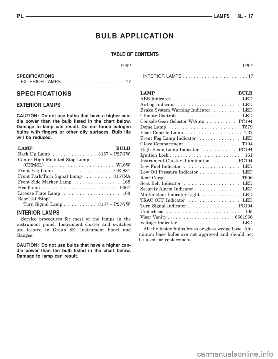
LAMP BULB
Back Up Lamp................3157 ± P27/7W
Center High Mounted Stop Lamp
(CHMSL).........................W16W
Front Fog Lamp..................... GE881
Front Park/Turn Signal Lamp..........3157NA
Front Side Marker Lamp................. 168
Headlamp............................9007
License Plate Lamp..................... 168
Rear Tail/Stop/
Turn Signal Lamp............3157 ± P27/7W
INTERIOR LAMPS
Service procedures for most of the lamps in the
instrument panel, Instrument cluster and switches
are located in Group 8E, Instrument Panel and
Gauges.
CAUTION: Do not use bulbs that have a higher can-
dle power than the bulb listed in the chart below.
Damage to lamp can result.LAMP BULB
ABS Indicator......................... LED
Airbag Indicator....................... LED
Brake System Warning Indicator.......... LED
Climate Controls....................... LED
Console Gear Selector W/Auto...........PC194
Dome Lamp..........................T579
Floor Console Lamp..................... T37
Front Fog Lamp Indicator................ LED
Glove Compartment....................T194
High Beam Lamp Indicator.............PC194
Ignition Lock........................... 161
Instrument Cluster Illumination.........PC194
Low Fuel Indicator..................... LED
Low Oil Pressure Indicator............... LED
Rear Cargo...........................T906
Seat Belt Indicator..................... LED
Security Alarm Indicator................. LED
Malfunction Indicator Light.............. LED
TRAC OFF Indicator.................... LED
Turn Signal Indicator..................PC194
Underhood............................ 105
Visor Vanity........................6501966
Voltage Indicator....................... LED
All the inside bulbs brass or glass wedge base. Alu-
minum base bulbs are not approved and should not
be used for replacement.
PLLAMPS 8L - 17
Page 344 of 1285

BULB APPLICATION
TABLE OF CONTENTS
page page
GENERAL INFORMATION
INTRODUCTION.........................19
SPECIFICATIONS
EXTERIOR LAMPS........................19INTERIOR LAMPS........................19
GENERAL INFORMATION
INTRODUCTION
The following Bulb Application Tables list the lamp
title on the left side of the column and trade number
or part number on the right.
CAUTION: Do not use bulbs that have a higher can-
dle power than the bulb listed in the Bulb Applica-
tion Table. Damage to lamp can result.
Do not touch halogen bulbs with fingers or other
possibly oily surfaces. Bulb life will be reduced.
If a halogen bulb is contaminated with oil, clean
bulb with denatured alcohol or ammonia based sol-
vent.
SPECIFICATIONS
EXTERIOR LAMPS
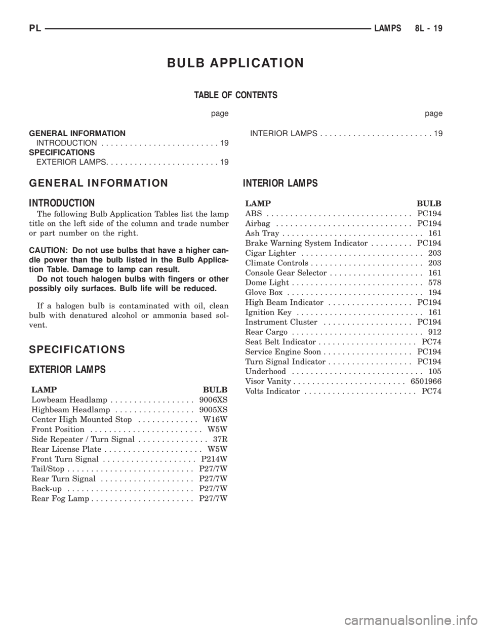
LAMP BULB
Lowbeam Headlamp..................9006XS
Highbeam Headlamp.................9005XS
Center High Mounted Stop.............W16W
Front Position........................ W5W
Side Repeater / Turn Signal............... 37R
Rear License Plate..................... W5W
Front Turn Signal....................P214W
Tail/Stop...........................P27/7W
Rear Turn Signal....................P27/7W
Back-up...........................P27/7W
Rear Fog Lamp......................P27/7W
INTERIOR LAMPS
LAMP BULB
ABS ...............................PC194
Airbag.............................PC194
AshTray .............................. 161
Brake Warning System Indicator.........PC194
Cigar Lighter.......................... 203
Climate Controls........................ 203
Console Gear Selector.................... 161
Dome Light............................ 578
Glove Box............................. 194
High Beam Indicator..................PC194
Ignition Key........................... 161
Instrument Cluster...................PC194
Rear Cargo............................ 912
Seat Belt Indicator.....................PC74
Service Engine Soon...................PC194
Turn Signal Indicator..................PC194
Underhood............................ 105
Visor Vanity........................6501966
Volts Indicator........................PC74
PLLAMPS 8L - 19
Page 397 of 1285

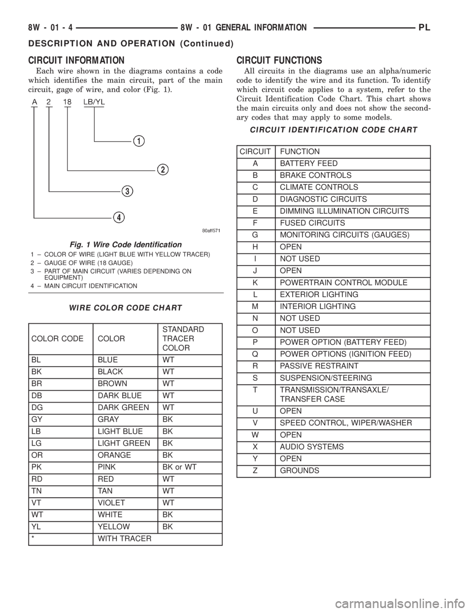
CIRCUIT INFORMATION
Each wire shown in the diagrams contains a code
which identifies the main circuit, part of the main
circuit, gage of wire, and color (Fig. 1).
CIRCUIT FUNCTIONS
All circuits in the diagrams use an alpha/numeric
code to identify the wire and its function. To identify
which circuit code applies to a system, refer to the
Circuit Identification Code Chart. This chart shows
the main circuits only and does not show the second-
ary codes that may apply to some models.
Fig. 1 Wire Code Identification
1 ± COLOR OF WIRE (LIGHT BLUE WITH YELLOW TRACER)
2 ± GAUGE OF WIRE (18 GAUGE)
3 ± PART OF MAIN CIRCUIT (VARIES DEPENDING ON
EQUIPMENT)
4 ± MAIN CIRCUIT IDENTIFICATION
WIRE COLOR CODE CHART
COLOR CODE COLORSTANDARD
TRACER
COLOR
BL BLUE WT
BK BLACK WT
BR BROWN WT
DB DARK BLUE WT
DG DARK GREEN WT
GY GRAY BK
LB LIGHT BLUE BK
LG LIGHT GREEN BK
OR ORANGE BK
PK PINK BK or WT
RD RED WT
TN TAN WT
VT VIOLET WT
WT WHITE BK
YL YELLOW BK
* WITH TRACER
CIRCUIT IDENTIFICATION CODE CHART
CIRCUIT FUNCTION
A BATTERY FEED
B BRAKE CONTROLS
C CLIMATE CONTROLS
D DIAGNOSTIC CIRCUITS
E DIMMING ILLUMINATION CIRCUITS
F FUSED CIRCUITS
G MONITORING CIRCUITS (GAUGES)
H OPEN
I NOT USED
J OPEN
K POWERTRAIN CONTROL MODULE
L EXTERIOR LIGHTING
M INTERIOR LIGHTING
N NOT USED
O NOT USED
P POWER OPTION (BATTERY FEED)
Q POWER OPTIONS (IGNITION FEED)
R PASSIVE RESTRAINT
S SUSPENSION/STEERING
T TRANSMISSION/TRANSAXLE/
TRANSFER CASE
U OPEN
V SPEED CONTROL, WIPER/WASHER
W OPEN
X AUDIO SYSTEMS
Y OPEN
Z GROUNDS
8W - 01 - 4 8W - 01 GENERAL INFORMATIONPL
DESCRIPTION AND OPERATION (Continued)
Page 1233 of 1285

GENERAL INFORMATION
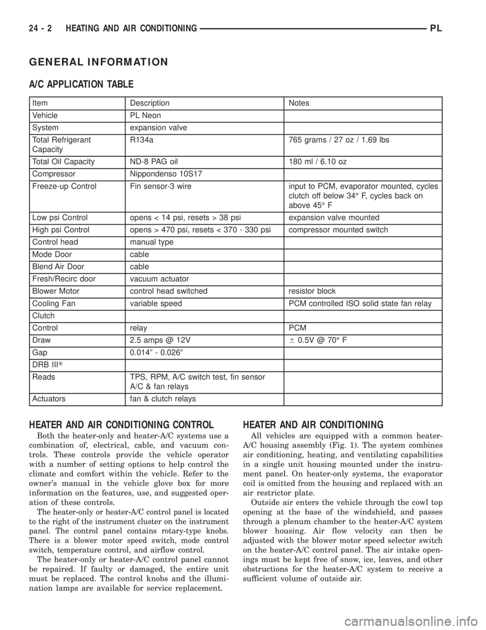
A/C APPLICATION TABLE
Item Description Notes
Vehicle PL Neon
System expansion valve
Total Refrigerant
CapacityR134a 765 grams / 27 oz / 1.69 lbs
Total Oil Capacity ND-8 PAG oil 180 ml / 6.10 oz
Compressor Nippondenso 10S17
Freeze-up Control Fin sensor-3 wire input to PCM, evaporator mounted, cycles
clutch off below 34É F, cycles back on
above 45É F
Low psi Control opens < 14 psi, resets > 38 psi expansion valve mounted
High psi Control opens > 470 psi, resets < 370 - 330 psi compressor mounted switch
Control head manual type
Mode Door cable
Blend Air Door cable
Fresh/Recirc door vacuum actuator
Blower Motor control head switched resistor block
Cooling Fan variable speed PCM controlled ISO solid state fan relay
Clutch
Control relay PCM
Draw 2.5 amps @ 12V60.5V @ 70É F
Gap 0.014º - 0.0269
DRB IIIT
Reads TPS, RPM, A/C switch test, fin sensor
A/C & fan relays
Actuators fan & clutch relays
HEATER AND AIR CONDITIONING CONTROL
Both the heater-only and heater-A/C systems use a
combination of, electrical, cable, and vacuum con-
trols. These controls provide the vehicle operator
with a number of setting options to help control the
climate and comfort within the vehicle. Refer to the
owner's manual in the vehicle glove box for more
information on the features, use, and suggested oper-
ation of these controls.
The heater-only or heater-A/C control panel is located
to the right of the instrument cluster on the instrument
panel. The control panel contains rotary-type knobs.
There is a blower motor speed switch, mode control
switch, temperature control, and airflow control.
The heater-only or heater-A/C control panel cannot
be repaired. If faulty or damaged, the entire unit
must be replaced. The control knobs and the illumi-
nation lamps are available for service replacement.
HEATER AND AIR CONDITIONING
All vehicles are equipped with a common heater-
A/C housing assembly (Fig. 1). The system combines
air conditioning, heating, and ventilating capabilities
in a single unit housing mounted under the instru-
ment panel. On heater-only systems, the evaporator
coil is omitted from the housing and replaced with an
air restrictor plate.
Outside air enters the vehicle through the cowl top
opening at the base of the windshield, and passes
through a plenum chamber to the heater-A/C system
blower housing. Air flow velocity can then be
adjusted with the blower motor speed selector switch
on the heater-A/C control panel. The air intake open-
ings must be kept free of snow, ice, leaves, and other
obstructions for the heater-A/C system to receive a
sufficient volume of outside air.
24 - 2 HEATING AND AIR CONDITIONINGPL