2000 DODGE NEON four wheel drive
[x] Cancel search: four wheel drivePage 81 of 1285
DESCRIPTION AND OPERATION
BASE BRAKE SYSTEM OPERATION
When a vehicle needs to be stopped, the driver
applies the brake pedal. The brake pedal pushes the
input rod of the power brake booster into the booster.
The booster uses vacuum to ease pedal effort as force
is transferred through the booster to the master cyl-
inder. The booster's output rod pushes in the master
cylinder's primary and secondary pistons applying
hydraulic pressure through the chassis brake tubes
and proportioning valves (rear only) to the brakes at
each tire and wheel assembly.
Front disc brakes control the braking of the front
wheels; rear braking is controlled by rear drum
brakes as standard equipment. Rear disc brakes and
an antilock brake system (ABS) with traction control
are optional.
The hydraulic brake system is diagonally split on
both the non-antilock and antilock braking systems.
This means the left front and right rear brakes are
on one hydraulic circuit and the right front and left
rear are on the other.
Vehicles equipped with the optional antilock brake
system (ABS) use a system designated Mark 20e.
This system shares most base brake hardware used
on vehicles without ABS. A vehicle equipped with
ABS, however, uses a different master cylinder and
brake tubes. Also included in the ABS system is an
integrated control unit (ICU) and four wheel speed
sensors. These components are described in detail in
the ANTILOCK BRAKE SYSTEM section in this
group of the service manual. All vehicles with ABS
come standard with four-wheel-disc brakes and trac-
tion control.
The parking brakes are hand-operated. When
applied, the parking brake lever pulls on cables that
actuate brake shoes at each rear wheel. The parking
brake lever has an automatic adjusting feature that
takes up any excessive slack in the parking brake
cable system.
BASE BRAKE SYSTEM COMPONENTS
BRAKE PEDAL
A suspended-type brake pedal is used on this vehi-
cle. The pedal pivots on a shaft mounted in the pedal
support bracket under the instrument panel. The
pedal connects to the power brake booster input rod
and pushes it in when the pedal is applied.
The brake pedal and it's pad are serviceable sepa-
rately.
POWER BRAKE BOOSTER
There are two different power brake booster
designs, although externally they appear the same.
All vehicles use a 205 mm tandem diaphragm power
brake booster. The two boosters are internally tuned
differently depending on whether the vehicle is
equipped with the standard front disc/rear drum
brake combination or the optional front disc/rear disc
(four-wheel disc) brake combination. If the power
brake booster requires replacement, be sure it is
replaced with the correct part.
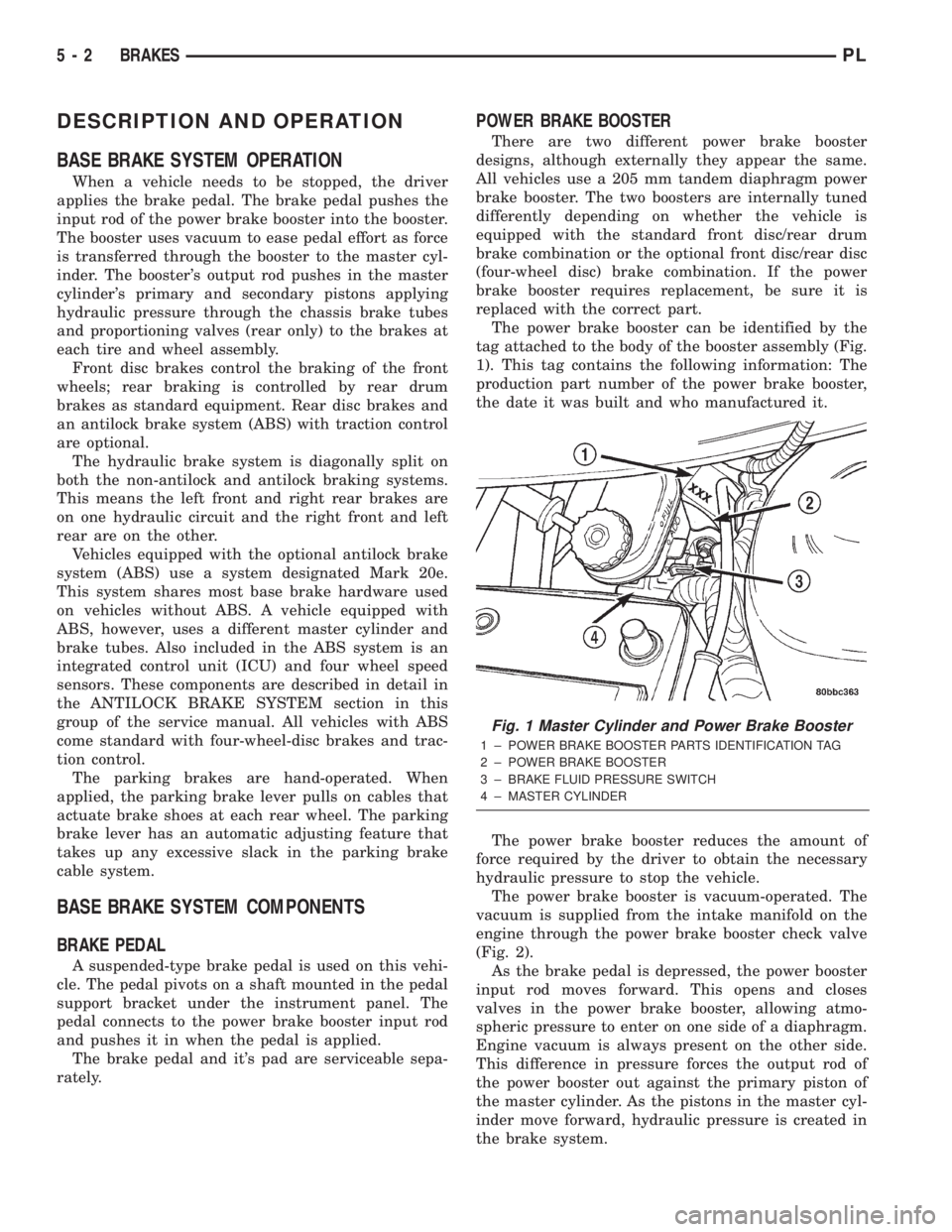
The power brake booster can be identified by the
tag attached to the body of the booster assembly (Fig.
1). This tag contains the following information: The
production part number of the power brake booster,
the date it was built and who manufactured it.
The power brake booster reduces the amount of
force required by the driver to obtain the necessary
hydraulic pressure to stop the vehicle.
The power brake booster is vacuum-operated. The
vacuum is supplied from the intake manifold on the
engine through the power brake booster check valve
(Fig. 2).
As the brake pedal is depressed, the power booster
input rod moves forward. This opens and closes
valves in the power brake booster, allowing atmo-
spheric pressure to enter on one side of a diaphragm.
Engine vacuum is always present on the other side.
This difference in pressure forces the output rod of
the power booster out against the primary piston of
the master cylinder. As the pistons in the master cyl-
inder move forward, hydraulic pressure is created in
the brake system.
Fig. 1 Master Cylinder and Power Brake Booster
1 ± POWER BRAKE BOOSTER PARTS IDENTIFICATION TAG
2 ± POWER BRAKE BOOSTER
3 ± BRAKE FLUID PRESSURE SWITCH
4 ± MASTER CYLINDER
5 - 2 BRAKESPL
Page 97 of 1285
CAUTION: Before removing the master cylinder
cap, wipe it clean to prevent dirt and other foreign
matter from dropping into the master cylinder res-
ervoir.
CAUTION: Use only MoparTbrake fluid or an equiv-
alent from a fresh, tightly sealed container. Brake
fluid must conform to DOT 3 specifications.
Do not pump the brake pedal at any time while
having a bleeder screw open during the bleeding pro-
cess. This will only increase the amount of air in the
system and make additional bleeding necessary.
Do not allow the master cylinder reservoir to run
out of brake fluid while bleeding the system. An
empty reservoir will allow additional air into the
brake system. Check the fluid level frequently and
add fluid as needed.
The following wheel circuit sequence for bleeding
the brake hydraulic system should be used to ensure
adequate removal of all trapped air from the hydrau-
lic system.
²Left rear wheel
²Right front wheel
²Right rear wheel
²Left front wheel
MANUAL BLEEDING
NOTE: To bleed the brakes manually, the aid of a
helper will be required.
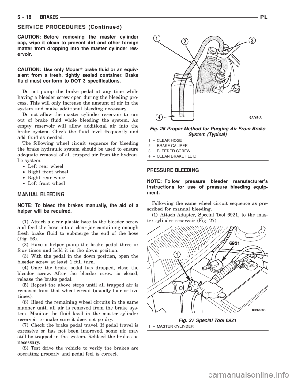
(1) Attach a clear plastic hose to the bleeder screw
and feed the hose into a clear jar containing enough
fresh brake fluid to submerge the end of the hose
(Fig. 26).
(2) Have a helper pump the brake pedal three or
four times and hold it in the down position.
(3) With the pedal in the down position, open the
bleeder screw at least 1 full turn.
(4) Once the brake pedal has dropped, close the
bleeder screw. After the bleeder screw is closed,
release the brake pedal.
(5) Repeat the above steps until all trapped air is
removed from that wheel circuit (usually four or five
times).
(6) Bleed the remaining wheel circuits in the same
manner until all air is removed from the brake sys-
tem. Monitor the fluid level in the master cylinder
reservoir to make sure it does not go dry.
(7) Check the brake pedal travel. If pedal travel is
excessive or has not been improved, some air may
still be trapped in the system. Rebleed the brakes as
necessary.
(8) Test drive the vehicle to verify the brakes are
operating properly and pedal feel is correct.
PRESSURE BLEEDING
NOTE: Follow pressure bleeder manufacturer's
instructions for use of pressure bleeding equip-
ment.
Following the same wheel circuit sequence as pre-
scribed for manual bleeding.
(1) Attach Adapter, Special Tool 6921, to the mas-
ter cylinder reservoir (Fig. 27).
Fig. 26 Proper Method for Purging Air From Brake
System (Typical)
1 ± CLEAR HOSE
2 ± BRAKE CALIPER
3 ± BLEEDER SCREW
4 ± CLEAN BRAKE FLUID
Fig. 27 Special Tool 6921
1 ± MASTER CYLINDER
5 - 18 BRAKESPL
SERVICE PROCEDURES (Continued)
Page 144 of 1285
ANTILOCK BRAKE SYSTEM
TABLE OF CONTENTS
page page
DESCRIPTION AND OPERATION
ANTILOCK BRAKE SYSTEM OPERATION......65
ANTILOCK BRAKE SYSTEM COMPONENTS....66
ELECTRONIC BRAKE DISTRIBUTION.........69
TRACTION CONTROL SYSTEM..............70
HYDRAULIC CIRCUITS AND VALVE
OPERATION...........................71
DIAGNOSIS AND TESTING
SERVICE WARNINGS AND CAUTIONS........74
ABS GENERAL DIAGNOSTICS INFORMATION . . 74
ABS WIRING DIAGRAM INFORMATION........74
ABS VEHICLE TEST DRIVE.................74
ABS ELECTRONIC DIAGNOSIS..............75
TONE WHEEL...........................76
BRAKE FLUID CONTAMINATION.............76
SERVICE PROCEDURES
BRAKE FLUID LEVEL CHECKING............77ANTILOCK BRAKE SYSTEM BLEEDING.......77
MASTER CYLINDER BLEEDING.............77
REMOVAL AND INSTALLATION
SERVICE WARNINGS AND CAUTIONS........78
MASTER CYLINDER......................78
INTEGRATED CONTROL UNIT...............79
WHEEL SPEED SENSOR (FRONT)...........81
WHEEL SPEED SENSOR (REAR)............83
DISASSEMBLY AND ASSEMBLY
INTEGRATED CONTROL UNIT...............84
SPECIFICATIONS
TONE WHEEL RUNOUT....................85
WHEEL SPEED SENSOR-TO-TONE WHEEL
CLEARANCE...........................85
BRAKE FASTENER TORQUE
SPECIFICATIONS.......................85
DESCRIPTION AND OPERATION
ANTILOCK BRAKE SYSTEM OPERATION
This section covers the physical and operational
descriptions, and the on-car service procedures for
the Mark 20e Antilock Brake System (ABS) with
traction control. It is the only antilock brake system
available on this vehicle.
The purpose of the antilock brake system is to pre-
vent wheel lockup under braking conditions on virtu-
ally any type of road surface. Antilock braking is
desirable because a vehicle that is stopped without
locking the wheels retains directional stability and
some steering capability. This allows the driver to
retain greater control of the vehicle during braking.
The traction control system reduces wheel slip and
maintains traction at the driving speeds below 56
kph (35 mph) when road conditions call for traction
assistance. Refer to TRACTION CONTROL SYSTEM
in this section for more information.
Vehicles equipped with ABS use electronic brake
distribution (EBD) to balance front-to-rear braking
when the brakes are applied in the partial braking
range. Refer to ELECTRONIC BRAKE DISTRIBU-
TION in this section for more information.
There are a few performance characteristics of the
Mark 20e Antilock Brake System that may at first
seem abnormal, but in fact are normal. These char-
acteristics are described below.
NORMAL BRAKING
Under normal braking conditions, the ABS func-
tions the same as a standard base brake system with
a diagonally split master cylinder and conventional
vacuum assist.
ABS BRAKING
ABS operation is available at all vehicle speeds
above 3±5 mph. If a wheel locking tendency is
detected during a brake application, the brake sys-
tem enters the ABS mode. During ABS braking,
hydraulic pressure in the four wheel circuits is mod-
ulated to prevent any wheel from locking. Each
wheel circuit is designed with a set of electric sole-
noids to allow modulation, although for vehicle sta-
bility, both rear wheel solenoids receive the same
electrical signal. Wheel lockup may be perceived at
the very end of an ABS stop and is considered nor-
mal.
During an ABS stop, the brakes hydraulic system
is still diagonally split. However, the brake system
pressure is further split into four control channels.
During antilock operation of the vehicle's brake sys-
tem, the wheels are controlled independently and are
on separate control channels.
The system can build, hold and release pressure at
each wheel, depending on signals generated by the
wheel speed sensors (WSS) at each wheel and
received at the controller antilock brake (CAB).
PLBRAKES 5 - 65
Page 147 of 1285
CONTROLLER ANTILOCK BRAKE INPUTS
²wheel speed sensors (four)
²stop lamp switch
²ignition switch
²system relay voltage
²ground
²traction control lamp
²diagnostic communication (PCI)
CONTROLLER ANTILOCK BRAKE OUTPUTS
²amber ABS warning lamp actuation (through
MIC)
²red BRAKE warning lamp actuation (through
MIC)
²traction control lamp actuation (through MIC)
²diagnostic communication. (PCI)
HYDRAULIC CONTROL UNIT (HCU)
The hydraulic control unit (HCU) is mounted to
the CAB as part of the ICU (Fig. 2). The HCU con-
trols the flow of brake fluid to the brakes using a
series of valves and accumulators. A pump/motor is
mounted on the HCU to supply build pressure to the
brakes during an ABS stop.
VALVES AND SOLENOIDS
The valve block contains four inlet valves and four
outlet solenoid valves. The inlet valves are spring-
loaded in the open position and the outlet valves are
spring-loaded in the closed position during normal
braking. The fluid is allowed to flow from the master
cylinder to the wheel brakes.
During an ABS stop, these valves cycle to maintain
the proper slip ratio for each wheel. The inlet valve
closes preventing further pressure increase and the
outlet valve opens to provide a path from the wheel
brake to the HCU accumulators and pump/motor.
This releases (decays) pressure from the wheel brake,
thus releasing the wheel from excessive slippage.
Once the wheel is no longer slipping, the outlet valve
is closed and the inlet valve is opened to reapply
(build) pressure.
There are four other valves in the HCU. These four
remaining valves are used for traction control. Two
traction control (TC) valves, mounted in the HCU
valve block, are normally in the open position and
close only when the traction control is applied. There
are also two shuttle valves which control pressure
return to the master cylinder under ABS and traction
control conditions.
These TC valves are used to isolate the rear (non-
driving) wheels of the vehicle from the hydraulic
pressure that the HCU pump/motor is sending to the
front (driving) wheels when traction control is being
applied. The rear brakes need to be isolated from the
master cylinder when traction control is beingapplied so the rear wheels do not drag. For more
information on the TC and shuttle valves, see TRAC-
TION CONTROL SYSTEM in this section.
BRAKE FLUID ACCUMULATORS
There are two fluid accumulators in the HCU: one
for the primary hydraulic circuit, and one for the sec-
ondary hydraulic circuit. Each hydraulic circuit uses
a 3 cc accumulator.
The fluid accumulators temporarily store brake
fluid that is removed from the wheel brakes during
an ABS cycle. This stored fluid is used by the pump/
motor to provide build pressure for the brake hydrau-
lic system. When the antilock stop is complete, the
accumulators are drained by the pump/motor.
There are two noise dampening chambers in the
HCU on this vehicle equipped with traction control.
PUMP/MOTOR
There are two pump assemblies in the HCU: one
for the primary hydraulic circuit, and one for the sec-
ondary hydraulic circuit. Both pumps are driven by a
common electric motor (Fig. 2). This DC-type motor
is integral to the HCU and is controlled by the CAB.
The pump/motor provides the extra amount of
brake fluid needed during antilock braking. Brake
fluid is released to the accumulators when the outlet
valve is opened during an antilock stop. The pump
mechanism consists of two opposing pistons operated
by an eccentric camshaft. In operation, these pistons
are used to purge fluid from the accumulators back
into the master cylinder circuits. When the antilock
stop is complete, the pump/motor drains the accumu-
lators.
The pump motor is also used to build pressure
when the system goes into traction control mode. For
more information, refer to TRACTION CONTROL
SYSTEM in this section.
The CAB may turn on the pump/motor when an
antilock stop is detected. The pump/motor continues
to run during the antilock stop and is turned off after
the stop is complete. Under some conditions, the
pump/motor runs to drain the accumulators during
the next drive-off.
The pump/motor is not a serviceable item; if it
requires replacement, the HCU must be replaced.
ABS FUSES
The ABS fuse and the ABS pump/motor fuse are
located in the power distribution center (PDC). Refer
to the sticker on the inside of the PDC cover for the
location of these fuses. The PDC is located on the
driver's side of the engine compartment between the
back of the battery and the brake master cylinder.
The CAB fuse can be found in the fuse junction
block under the instrument panel.
5 - 68 BRAKESPL
DESCRIPTION AND OPERATION (Continued)
Page 166 of 1285
CLUTCH
TABLE OF CONTENTS
page page
DESCRIPTION AND OPERATION
MODULAR CLUTCH ASSEMBLY..............1
CLUTCH CABLE..........................1
CLUTCH INTERLOCK/UPSTOP SWITCH........1
DIAGNOSIS AND TESTING
CLUTCH SYSTEM DIAGNOSIS...............2
DRIVE PLATE MISALIGNMENT..............5
CLUTCH CHATTER COMPLAINTS............5
CLASH±INTO±REVERSE COMPLAINTS........5
CLUTCH INTERLOCK/UPSTOP SWITCH........5REMOVAL AND INSTALLATION
CLUTCH CABLE..........................7
CLUTCH INTERLOCK/UPSTOP SWITCH........8
MODULAR CLUTCH ASSEMBLY..............8
RELEASE BEARING AND FORK.............12
CLEANING AND INSPECTION
CLUTCH CONTAMINATION.................12
CLEANING PRECAUTIONS.................13
SPECIFICATIONS
TORQUE...............................13
DESCRIPTION AND OPERATION
MODULAR CLUTCH ASSEMBLY
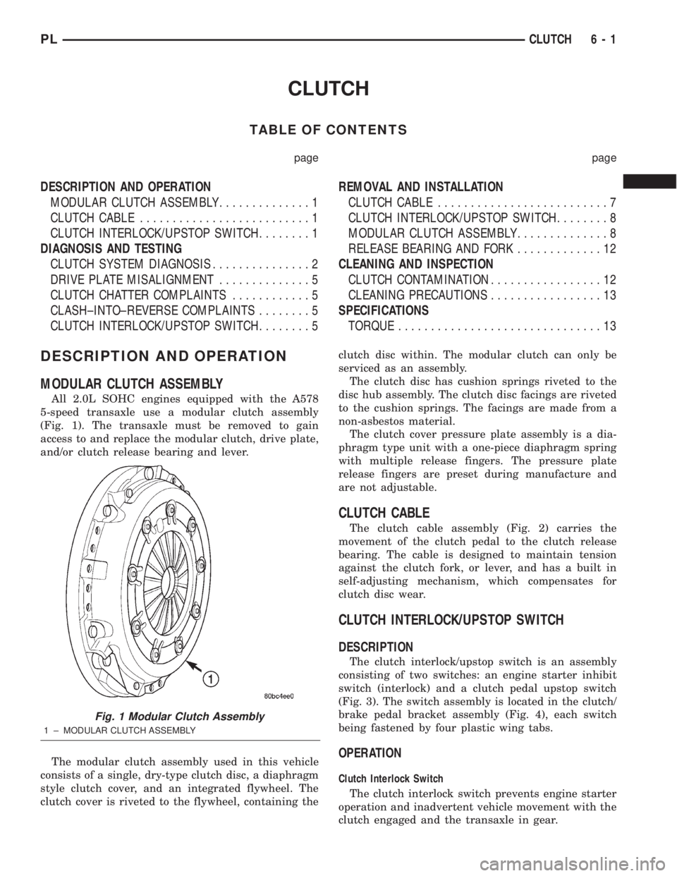
All 2.0L SOHC engines equipped with the A578
5-speed transaxle use a modular clutch assembly
(Fig. 1). The transaxle must be removed to gain
access to and replace the modular clutch, drive plate,
and/or clutch release bearing and lever.
The modular clutch assembly used in this vehicle
consists of a single, dry-type clutch disc, a diaphragm
style clutch cover, and an integrated flywheel. The
clutch cover is riveted to the flywheel, containing theclutch disc within. The modular clutch can only be
serviced as an assembly.
The clutch disc has cushion springs riveted to the
disc hub assembly. The clutch disc facings are riveted
to the cushion springs. The facings are made from a
non-asbestos material.
The clutch cover pressure plate assembly is a dia-
phragm type unit with a one-piece diaphragm spring
with multiple release fingers. The pressure plate
release fingers are preset during manufacture and
are not adjustable.
CLUTCH CABLE
The clutch cable assembly (Fig. 2) carries the
movement of the clutch pedal to the clutch release
bearing. The cable is designed to maintain tension
against the clutch fork, or lever, and has a built in
self-adjusting mechanism, which compensates for
clutch disc wear.
CLUTCH INTERLOCK/UPSTOP SWITCH
DESCRIPTION
The clutch interlock/upstop switch is an assembly
consisting of two switches: an engine starter inhibit
switch (interlock) and a clutch pedal upstop switch
(Fig. 3). The switch assembly is located in the clutch/
brake pedal bracket assembly (Fig. 4), each switch
being fastened by four plastic wing tabs.
OPERATION
Clutch Interlock Switch
The clutch interlock switch prevents engine starter
operation and inadvertent vehicle movement with the
clutch engaged and the transaxle in gear.
Fig. 1 Modular Clutch Assembly
1 ± MODULAR CLUTCH ASSEMBLY
PLCLUTCH 6 - 1
Page 170 of 1285
DRIVE PLATE MISALIGNMENT
Common causes of misalignment are:
²Heat warping
²Mounting drive plate on a dirty crankshaft
flange
²Incorrect bolt tightening
²Improper seating on the crankshaft shoulder
²Loose crankshaft bolts
Clean the crankshaft flange before mounting the
drive plate. Dirt and grease on the flange surface
may misalign the flywheel, causing excessive runout.
Use new bolts when mounting drive plate to crank-
shaft. Tighten drive plate bolts to specified torque
only. Over-tightening can distort the drive plate hub
causing excessive runout.
CLUTCH CHATTER COMPLAINTS
For all clutch chatter complaints, do the following:
(1) Check for loose, misaligned, or broken engine
and transmission mounts. If present, they should be
corrected at this time. Test vehicle for chatter. If
chatter is gone, there is no need to go any further. If
chatter persists:
(2) Check to see if clutch cable routing is correct
and operates smoothly.
(3) Check for loose connections in drive train. Cor-
rect any problems and determine if clutch chatter
complaints have been satisfied. If not:
(4) Remove transaxle. See Group 21, Manual Tran-
saxle for procedure.
(5) Check to see if the release bearing is sticky or
binding. Replace bearing, if needed.
(6) Check linkage for excessive wear on the pivot
stud and fork fingers. Replace all worn parts.
(7) Check clutch assembly for contamination (dirt,
oil). Replace clutch assembly, if required.
(8) Check to see if the clutch disc hub splines are
damaged. Replace with new clutch assembly, if nec-
essary.
(9) Check input shaft splines for damage. Replace,
if necessary.
(10) Check for uneven wear on clutch fingers.
(11) Check for broken clutch cover diaphragm
spring fingers. Replace with new clutch assembly, if
necessary.
CLASH±INTO±REVERSE COMPLAINTS
Certain NV T350 (A-578) manual transaxles are
equipped with a reverse brake. It prevents clash
when shifting into reverse, but only if the vehicle is
not moving. See Group 21, Transaxle for further
diagnosis.
(1) Depress clutch pedal to floor and hold. After
three seconds, shift to reverse. If clash is present,
clutch has excessive spin time, and the reverse brake
may not be functioning.(2) Remove transaxle. See Group 21, Manual Tran-
saxle for procedure.
(3) Check the input shaft spline, clutch disc
splines, and release bearing for dry rust. If present,
clean rust off and apply a light coat of bearing grease
to the input shaft splines. Apply grease on the input
shaft splines only where the clutch disc slides. Verify
that the clutch disc slides freely along the input shaft
spline.
(4) Check to see if the clutch disc hub splines are
damaged, and replace with new clutch assembly if
required.
(5) Check the input shaft for damaged splines.
Replace as necessary.
(6) Check for broken clutch cover diaphragm
spring fingers.
(7) Install clutch assembly and transaxle.
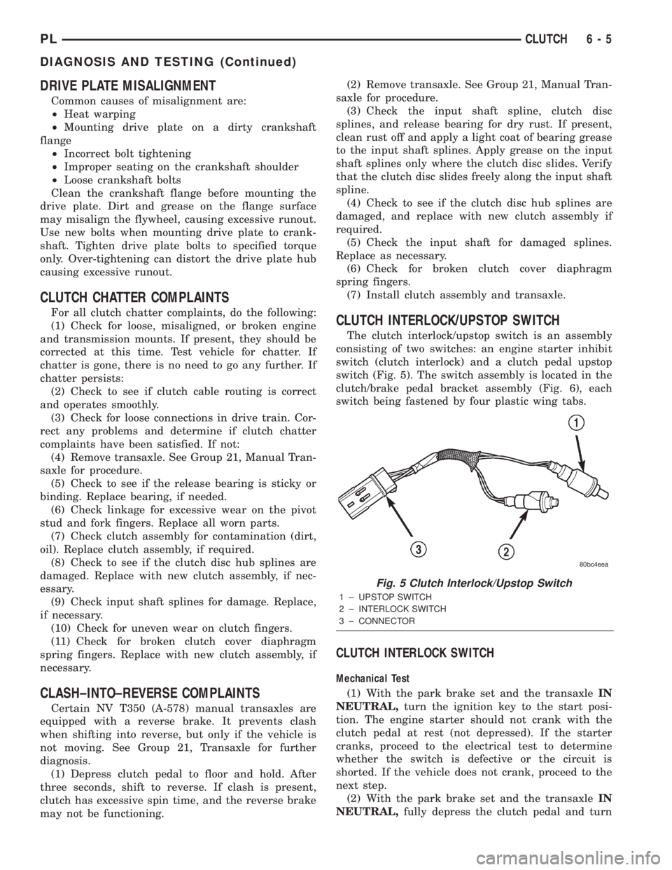
CLUTCH INTERLOCK/UPSTOP SWITCH
The clutch interlock/upstop switch is an assembly
consisting of two switches: an engine starter inhibit
switch (clutch interlock) and a clutch pedal upstop
switch (Fig. 5). The switch assembly is located in the
clutch/brake pedal bracket assembly (Fig. 6), each
switch being fastened by four plastic wing tabs.
CLUTCH INTERLOCK SWITCH
Mechanical Test
(1) With the park brake set and the transaxleIN
NEUTRAL,turn the ignition key to the start posi-
tion. The engine starter should not crank with the
clutch pedal at rest (not depressed). If the starter
cranks, proceed to the electrical test to determine
whether the switch is defective or the circuit is
shorted. If the vehicle does not crank, proceed to the
next step.
(2) With the park brake set and the transaxleIN
NEUTRAL,fully depress the clutch pedal and turn
Fig. 5 Clutch Interlock/Upstop Switch
1 ± UPSTOP SWITCH
2 ± INTERLOCK SWITCH
3 ± CONNECTOR
PLCLUTCH 6 - 5
DIAGNOSIS AND TESTING (Continued)
Page 390 of 1285
CHIME WARNING/REMINDER SYSTEM
TABLE OF CONTENTS
page page
DESCRIPTION AND OPERATION
INTRODUCTION..........................1
DIAGNOSIS AND TESTING
FASTEN SEAT BELTS......................1
HEADLAMPS LEFT ON.....................1
KEY LEFT IN IGNITION SWITCH.............1CHIME SYSTEM CONDITIONS...............1
REMOVAL AND INSTALLATION
CHIME..................................2
SEAT BELT BUCKLE.......................2
HEADLAMP SWITCH......................2
KEY-IN SWITCH..........................2
DESCRIPTION AND OPERATION
INTRODUCTION
WARNING: ON VEHICLES EQUIPPED WITH AN AIR-
BAG, REFER TO THE AIRBAG PORTION OF THIS
SECTION FOR STEERING WHEEL OR SWITCH
REMOVAL AND INSTALLATION PROCEDURES.
The seat belt reminder system uses both visual
and audible signals. A combined seat belt and key
reminder chime with a red light on the instrument
panel.
The system will always illuminate the seat belt
reminder lamp for four to eight seconds when the
ignition switch is turned to the ON position. The
CHIME will sound during the same time interval if
the driver's seat belt is not fastened. Passenger belts
are not connected to the system.
The chime will activate if the drivers door is
opened and:
²The key is in the ignition switch, with the igni-
tion switch in either the OFF or accessory (ACC)
position.
²The head lamps are ON.
The chime is integral to the instrument cluster.
DIAGNOSIS AND TESTING
FASTEN SEAT BELTS
To test the fasten seat belts function, turn the igni-
tion switch to the ON position with the driver's seat
belt unbuckled and fully retracted. The seat belt
warning lamp should light for four to eight seconds
and the tone should sound three to five times.
If the lamp does not light, check the connection at
the seat belt retractor and the LED in the instru-
ment cluster. Replace as necessary.
HEADLAMPS LEFT ON
These are the conditions that have to be met for
the headlamps on, chime function to work:
²Headlamps ON.
²Driver's door open.
²Key removed from the ignition switch.
Chime should sound until headlamps are turned
off or driver's door is closed.
If these conditions are met and there is still a
problem with the system, replace the instrument
cluster. Refer to Group 8E-Instrument Panel and
Systems, Instrument Cluster Removal and Installa-
tion.
KEY LEFT IN IGNITION SWITCH
To test the key left in ignition function, insert key
into the ignition and open the driver's door. Chime
should sound until key is removed from ignition or
driver's door is closed.
If these conditions are met and there is still a
problem with the system, replace the instrument
cluster. Refer to Group 8E-Instrument Panel and
Systems, Instrument Cluster Removal and Installa-
tion.
CHIME SYSTEM CONDITIONS
NO TONE WHEN IGNITION SWITCH IS TURNED ON
AND DRIVERS SEAT BELT IS UNBUCKLED
(1) Using an ohmmeter, with the seat belt fully
retracted, check for continuity to ground at Pin 25 of
the cluster harness connector. If OK, go to step 2. If
not OK, repair as necessary.
(2) Using voltmeter, check for battery feed at Pin
21 of the cluster harness connector. Check for igni-
tion feed at Pin 15 of the cluster harness connector.
If not OK, repair as necessary.
PLCHIME WARNING/REMINDER SYSTEM 8U - 1
Page 811 of 1285
CAUTION: After removing the steering knuckle from
the ball joint stud, do not pull outward on the knuckle.
Pulling the steering knuckle outward at this point can
separate the inner C/V joint on the driveshaft. Refer to
FRONT DRIVESHAFTS in the DIFFERENTIAL AND
DRIVELINE group for further information.
NOTE: Use caution when separating the ball joint
stud from the steering knuckle, so the ball joint seal
does not get cut.
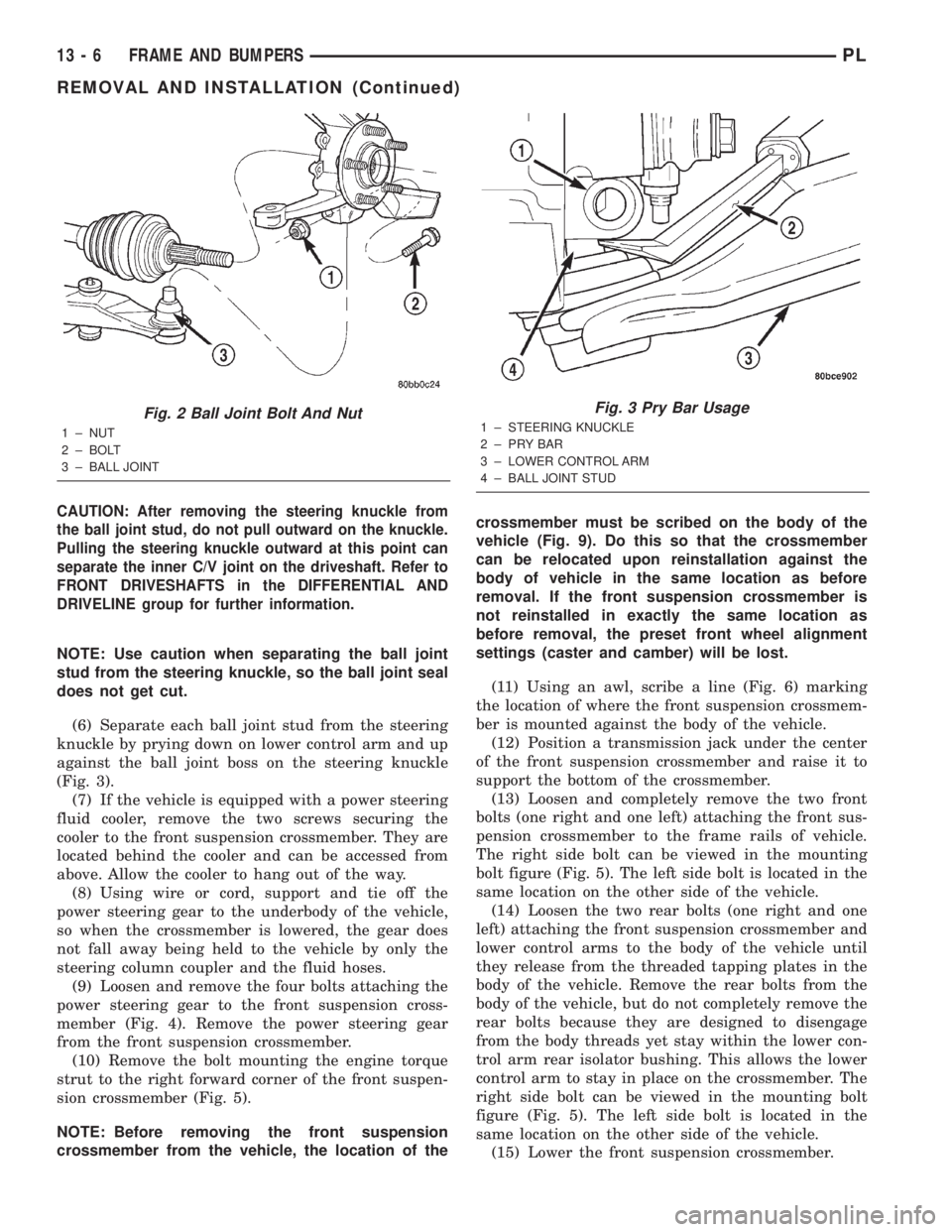
(6) Separate each ball joint stud from the steering
knuckle by prying down on lower control arm and up
against the ball joint boss on the steering knuckle
(Fig. 3).
(7) If the vehicle is equipped with a power steering
fluid cooler, remove the two screws securing the
cooler to the front suspension crossmember. They are
located behind the cooler and can be accessed from
above. Allow the cooler to hang out of the way.
(8) Using wire or cord, support and tie off the
power steering gear to the underbody of the vehicle,
so when the crossmember is lowered, the gear does
not fall away being held to the vehicle by only the
steering column coupler and the fluid hoses.
(9) Loosen and remove the four bolts attaching the
power steering gear to the front suspension cross-
member (Fig. 4). Remove the power steering gear
from the front suspension crossmember.
(10) Remove the bolt mounting the engine torque
strut to the right forward corner of the front suspen-
sion crossmember (Fig. 5).
NOTE: Before removing the front suspension
crossmember from the vehicle, the location of thecrossmember must be scribed on the body of the
vehicle (Fig. 9). Do this so that the crossmember
can be relocated upon reinstallation against the
body of vehicle in the same location as before
removal. If the front suspension crossmember is
not reinstalled in exactly the same location as
before removal, the preset front wheel alignment
settings (caster and camber) will be lost.
(11) Using an awl, scribe a line (Fig. 6) marking
the location of where the front suspension crossmem-
ber is mounted against the body of the vehicle.
(12) Position a transmission jack under the center
of the front suspension crossmember and raise it to
support the bottom of the crossmember.
(13) Loosen and completely remove the two front
bolts (one right and one left) attaching the front sus-
pension crossmember to the frame rails of vehicle.
The right side bolt can be viewed in the mounting
bolt figure (Fig. 5). The left side bolt is located in the
same location on the other side of the vehicle.
(14) Loosen the two rear bolts (one right and one
left) attaching the front suspension crossmember and
lower control arms to the body of the vehicle until
they release from the threaded tapping plates in the
body of the vehicle. Remove the rear bolts from the
body of the vehicle, but do not completely remove the
rear bolts because they are designed to disengage
from the body threads yet stay within the lower con-
trol arm rear isolator bushing. This allows the lower
control arm to stay in place on the crossmember. The
right side bolt can be viewed in the mounting bolt
figure (Fig. 5). The left side bolt is located in the
same location on the other side of the vehicle.
(15) Lower the front suspension crossmember.
Fig. 2 Ball Joint Bolt And Nut
1 ± NUT
2 ± BOLT
3 ± BALL JOINT
Fig. 3 Pry Bar Usage
1 ± STEERING KNUCKLE
2±PRYBAR
3 ± LOWER CONTROL ARM
4 ± BALL JOINT STUD
13 - 6 FRAME AND BUMPERSPL
REMOVAL AND INSTALLATION (Continued)