2000 DODGE NEON ad blue
[x] Cancel search: ad bluePage 397 of 1285

CIRCUIT INFORMATION
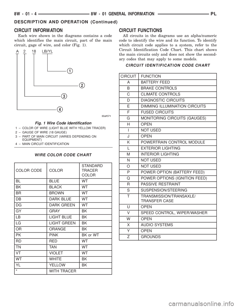
Each wire shown in the diagrams contains a code
which identifies the main circuit, part of the main
circuit, gage of wire, and color (Fig. 1).
CIRCUIT FUNCTIONS
All circuits in the diagrams use an alpha/numeric
code to identify the wire and its function. To identify
which circuit code applies to a system, refer to the
Circuit Identification Code Chart. This chart shows
the main circuits only and does not show the second-
ary codes that may apply to some models.
Fig. 1 Wire Code Identification
1 ± COLOR OF WIRE (LIGHT BLUE WITH YELLOW TRACER)
2 ± GAUGE OF WIRE (18 GAUGE)
3 ± PART OF MAIN CIRCUIT (VARIES DEPENDING ON
EQUIPMENT)
4 ± MAIN CIRCUIT IDENTIFICATION
WIRE COLOR CODE CHART
COLOR CODE COLORSTANDARD
TRACER
COLOR
BL BLUE WT
BK BLACK WT
BR BROWN WT
DB DARK BLUE WT
DG DARK GREEN WT
GY GRAY BK
LB LIGHT BLUE BK
LG LIGHT GREEN BK
OR ORANGE BK
PK PINK BK or WT
RD RED WT
TN TAN WT
VT VIOLET WT
WT WHITE BK
YL YELLOW BK
* WITH TRACER
CIRCUIT IDENTIFICATION CODE CHART
CIRCUIT FUNCTION
A BATTERY FEED
B BRAKE CONTROLS
C CLIMATE CONTROLS
D DIAGNOSTIC CIRCUITS
E DIMMING ILLUMINATION CIRCUITS
F FUSED CIRCUITS
G MONITORING CIRCUITS (GAUGES)
H OPEN
I NOT USED
J OPEN
K POWERTRAIN CONTROL MODULE
L EXTERIOR LIGHTING
M INTERIOR LIGHTING
N NOT USED
O NOT USED
P POWER OPTION (BATTERY FEED)
Q POWER OPTIONS (IGNITION FEED)
R PASSIVE RESTRAINT
S SUSPENSION/STEERING
T TRANSMISSION/TRANSAXLE/
TRANSFER CASE
U OPEN
V SPEED CONTROL, WIPER/WASHER
W OPEN
X AUDIO SYSTEMS
Y OPEN
Z GROUNDS
8W - 01 - 4 8W - 01 GENERAL INFORMATIONPL
DESCRIPTION AND OPERATION (Continued)
Page 624 of 1285

RED
BLACKBLACK
RED
- M1 20PK
G120 18WT/DBM2 18YL-
Z1 18BK Z1 18BK
C301
CAV CIRCUIT
1
2
4 3
6 5
-
C301
5
6 3
4 2 1CIRCUIT CAV
M2 18YL
G120 18WT/DB M1 20PK
1 36 4
-
134
6
-
L50 20WT/TN
G71 20VT/YL G78 18TN/BK
5
6 3
4 1CIRCUIT CAV
C302
Z1 18BK
C302
Q2 16LG/BK
BUILT-UP-EXPORT ELECTRIC RELEASE
CARGO LAMP
Z1 20BK 2
Q2 16LG/BK Z1 18BK CAV CIRCUIT
1
2
4 3
6 5
G78 22TN/BK
G71 20VT/YL L50 20WT/TN
-
1 46
3
3 64
1
EXCEPT ELECTRIC RELEASE
C304P33 18OR/BK
5
6
7 3
4 2 1CIRCUIT CAV
C304
1
7 7
1
P36 18PK/VT-
-
-
-
-- - - - -
P36 18PK/VT
CAV CIRCUIT
1
2
4 3
7 6 5P33 18OR/BK
P33 18OR/BK
5
6
7 3
4 2 1CIRCUIT CAV
P36 18PK/VT-
-
-
-
- - - - - -
P36 18PK/VT 1 7
7 1
C303
CAV CIRCUIT
1
2
4 3
7 6 5P33 18OR/BK
C303
BLUE
BLUE
BLACK
BLACK
PL8W-80 CONNECTOR PIN-OUTS 8W - 80 - 15
PLI08015008W-10
Page 631 of 1285

DRIVER POWER
WINDOW MOTOR
1
2
BLACK
DRIVER WINDOW DRIVER UP 14LB Q11 2DRIVER WINDOW DRIVER DOWN 14WT/LB Q21 1
FUNCTION CIRCUIT CAV
POWER MIRROR FOLD POWER MIRROR FOLD
P160 18LBP160 18LBPOWER MIRROR UNFOLD
P159 18DGPOWER MIRROR UNFOLD
P159 18DG 7
17
1
DRIVER POWER
MIRROR
(RHD)POWER MIRROR VERTICAL
P92 20YL P92 20YL P93 20YL/WT C16 20LB/YL
POWER MIRROR HORIZONTAL HEATED MIRRORFUNCTIONP95 20DB/WT
CAV CIRCUIT
1
2
4 3
6 5
Z8 20BK/VT
GROUND
7POWER MIRROR COMMON
POWER MIRROR COMMON
POWER MIRROR COMMON POWER MIRROR COMMON
- - 7
GROUND Z8 20BK/VT
5
6 3
4 2 1CIRCUIT CAVP91 20WT/BK-
FUNCTION
HEATED MIRROR
POWER MIRROR HORIZONTAL C16 20LB/YL
P94 20WT/YL
P92 20YL
P92 20YLPOWER MIRROR VERTICAL-
(LHD)
MIRROR DRIVER POWER
GRAY
BLUE
8W - 80 - 22 8W-80 CONNECTOR PIN-OUTSPL
008W-10PLI08022
Page 640 of 1285

MOTOR DOOR LOCKLEFT REAR
DOOR LOCK DRIVER 18OR/BK P33 DOOR UNLOCK DRIVER 18PK/VT P36
CAV CIRCUIT FUNCTION
1
B3 20LG/DB LEFT REAR WHEEL SPEED SENSOR (-) 2B4 20LG1
BLUE
2
LEFT REAR
WHEEL SPEED
SENSOR SPEAKER LEFT REAR
2 1
BLACK
LEFT REAR SPEAKER (-) 18BR/LB X57
2
LEFT REAR SPEAKER (+) 18BR/YL X51 1
FUNCTION CIRCUIT CAV
12-VOLT SUPPLY BLACK
34
2 1CAV
3
4 2
- - 1
FUNCTION CIRCUIT
--
REAR FOG LAMP FEED
L38 16BR/WT L250 18YL
31
FOG LAMP LEFT REAR
GROUND
Z1 16BKFUNCTION
CAV CIRCUIT
1
2
3
1 3
L63 18DG/RD LEFT TURN SIGNAL
3 2
GROUND 18BK Z1 1
FUNCTION CIRCUIT CAV
(BUILT-UP-EXPORT)LEFT REAR TURN
SIGNAL LAMP
--
(BUILT-UP-EXPORT)
DUMMY CIRCUIT PLUG
GRAY
GRAY
PL8W-80 CONNECTOR PIN-OUTS 8W - 80 - 31
PLI08031008W-10
Page 644 of 1285

1 2
BLACK
PASSENGER WINDOW DRIVER (UP) 14BR Q12 2PASSENGER WINDOW DRIVER (DOWN) 14VT Q22 1
FUNCTION CIRCUIT CAV
14VT Q22 MASTER WINDOW SWITCH RIGHT FRONT UP 14BR/WT Q16
FUSED IGNITION SWITCH OUTPUT (RUN) 14TN F21 MASTER WINDOW SWITCH RIGHT FRONT DOWN 14VT/WT Q26
14BR Q12
PASSENGER POWER
WINDOW MOTOR
PASSENGER POWER
WINDOW SWITCH
PASSENGER WINDOW DRIVER (DOWN)
PASSENGER WINDOW DRIVER (UP)
GRAY
8
6 5
4
3
2
1
FUNCTION CIRCUIT CAV
5 81 4
--
7F20 20WT
FUSED IGNITION SWITCH OUTPUT (RUN)
F20 20WT
FUSED IGNITION SWITCH OUTPUT (RUN)
Z14 18BK/YL
GROUND 7
17
1
PASSENGER POWER
MIRROR
(RHD)
POWER MIRROR COMMON
- - 7
GROUND Z14 18BK/YL
5
6 3
4 2 1CIRCUIT CAVP95 20DB/WT-
FUNCTION
HEATED MIRROR
POWER MIRROR HORIZONTAL C16 20LB/YL
P93 20YL/WT
P92 20YLPOWER MIRROR VERTICAL-
(LHD)
MIRROR PASSENGER POWER
Z14 18BK/YL
GROUND
GROUND Z14 18BK/YL
POWER MIRROR UNFOLD
P160 18LB P94 20WT/YL C16 20LB/YL
POWER MIRROR HORIZONTAL HEATED MIRRORFUNCTION
P159 18DG/WT
CAV CIRCUIT
1
2
4 3
6 5
Z14 18BK/YL
GROUND
7
POWER MIRROR FOLD
P91 20WT/BKPOWER MIRROR VERTICAL
P92 20YLPOWER MIRROR COMMON
BLACK
CAV CIRCUIT FUNCTION
1 F20 20WT FUSED IGNITION SWITCH OUTPUT (RUN)
2P96 18LG PASSENGER DOOR SWITCH MUX
PASSENGER DOOR
LOCK SWITCH
3
1
GROUND Z14 18BK/YL
3PASSENGER DOOR SWITCH MUX P96 18LG
Z14 18BK GROUND
GRAY
BLUE
PL8W-80 CONNECTOR PIN-OUTS 8W - 80 - 35
PLI08035008W-10
Page 653 of 1285

CAV CIRCUIT FUNCTION
1
X52 18DB/WT 2X58 18DB/OR RIGHT REAR SPEAKER (-)
B1 20YL/DB B2 20YL
BLACK
1 2
RIGHT REAR
SPEAKERRIGHT REAR SPEAKER (+)
SENSOR WHEEL SPEEDRIGHT REAR
2BLUE1 12-VOLT SUPPLY
2
RIGHT REAR WHEEL SPEED SENSOR (-) 1
FUNCTION CIRCUIT CAV
GROUND Z1 20BK 2RIGHT TURN SIGNAL L60 20TN 1
FUNCTION CIRCUIT CAV
REAR FOG LAMP FEED
L38 16BR/WTDUMMY CIRCUIT PLUG
L250 18YL
FOG LAMP RIGHT REAR
GROUND
Z1 16BKFUNCTION
CAV CIRCUIT
1
2
331
(BUILT-UP-EXPORT)LAMP RIGHT REPEATER
1 3
(BUILT-UP-EXPORT)
CAV CIRCUIT FUNCTION
1 Z1 18BK GROUND
2
3 L62 18BR/RD RIGHT TURN SIGNAL
RIGHT REAR TURN
SIGNAL LAMP
--
(BUILT-UP-EXPORT)
GRAY
GRAY
BLACK21
8W - 80 - 44 8W-80 CONNECTOR PIN-OUTSPL
008W-10PLI08044
Page 784 of 1285

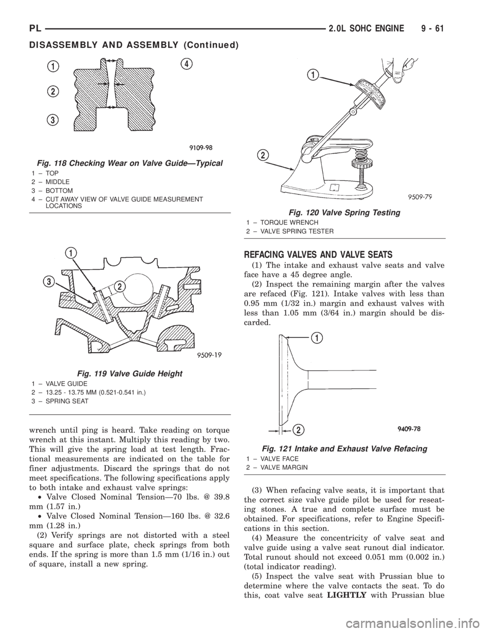
wrench until ping is heard. Take reading on torque
wrench at this instant. Multiply this reading by two.
This will give the spring load at test length. Frac-
tional measurements are indicated on the table for
finer adjustments. Discard the springs that do not
meet specifications. The following specifications apply
to both intake and exhaust valve springs:
²Valve Closed Nominal TensionÐ70 lbs. @ 39.8
mm (1.57 in.)
²Valve Closed Nominal TensionÐ160 lbs. @ 32.6
mm (1.28 in.)
(2) Verify springs are not distorted with a steel
square and surface plate, check springs from both
ends. If the spring is more than 1.5 mm (1/16 in.) out
of square, install a new spring.
REFACING VALVES AND VALVE SEATS
(1) The intake and exhaust valve seats and valve
face have a 45 degree angle.
(2) Inspect the remaining margin after the valves
are refaced (Fig. 121). Intake valves with less than
0.95 mm (1/32 in.) margin and exhaust valves with
less than 1.05 mm (3/64 in.) margin should be dis-
carded.
(3) When refacing valve seats, it is important that
the correct size valve guide pilot be used for reseat-
ing stones. A true and complete surface must be
obtained. For specifications, refer to Engine Specifi-
cations in this section.
(4) Measure the concentricity of valve seat and
valve guide using a valve seat runout dial indicator.
Total runout should not exceed 0.051 mm (0.002 in.)
(total indicator reading).
(5) Inspect the valve seat with Prussian blue to
determine where the valve contacts the seat. To do
this, coat valve seatLIGHTLYwith Prussian blue
Fig. 118 Checking Wear on Valve GuideÐTypical
1±TOP
2 ± MIDDLE
3 ± BOTTOM
4 ± CUT AWAY VIEW OF VALVE GUIDE MEASUREMENT
LOCATIONS
Fig. 119 Valve Guide Height
1 ± VALVE GUIDE
2 ± 13.25 - 13.75 MM (0.521-0.541 in.)
3 ± SPRING SEAT
Fig. 120 Valve Spring Testing
1 ± TORQUE WRENCH
2 ± VALVE SPRING TESTER
Fig. 121 Intake and Exhaust Valve Refacing
1 ± VALVE FACE
2 ± VALVE MARGIN
PL2.0L SOHC ENGINE 9 - 61
DISASSEMBLY AND ASSEMBLY (Continued)
Page 785 of 1285

then set valve in place. Rotate the valve with light
pressure. If the blue is transferred to the center of
valve face, contact is satisfactory. If the blue is trans-
ferred to top edge of the valve face, lower valve seat
with a 15 degrees stone. If the blue is transferred to
the bottom edge of valve face raise valve seat with a
65 degrees stone.
(6) Valve seats which are worn or burned can be
reworked, provided that correct angle and seat width
are maintained. The intake valve seat must be ser-
viced when the valve seat width is 2.0 mm (0.079 in.)
or greater. The exhaust valve seat must be serviced
when the valve seat width is 2.5 mm (0.098 in.) or
greater. Otherwise the cylinder head must be
replaced.
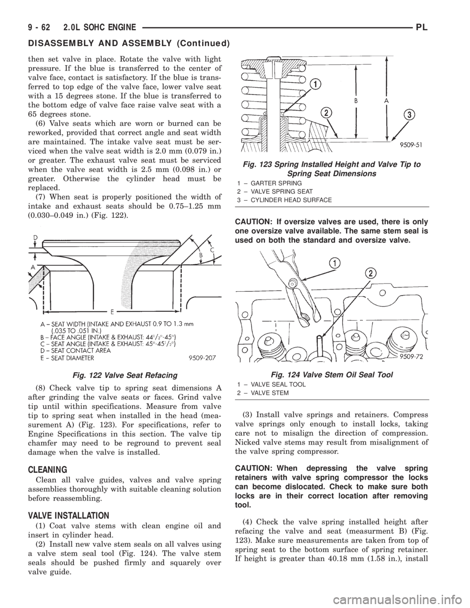
(7) When seat is properly positioned the width of
intake and exhaust seats should be 0.75±1.25 mm
(0.030±0.049 in.) (Fig. 122).
(8) Check valve tip to spring seat dimensions A
after grinding the valve seats or faces. Grind valve
tip until within specifications. Measure from valve
tip to spring seat when installed in the head (mea-
surement A) (Fig. 123). For specifications, refer to
Engine Specifications in this section. The valve tip
chamfer may need to be reground to prevent seal
damage when the valve is installed.
CLEANING
Clean all valve guides, valves and valve spring
assemblies thoroughly with suitable cleaning solution
before reassembling.
VALVE INSTALLATION
(1) Coat valve stems with clean engine oil and
insert in cylinder head.
(2) Install new valve stem seals on all valves using
a valve stem seal tool (Fig. 124). The valve stem
seals should be pushed firmly and squarely over
valve guide.CAUTION: If oversize valves are used, there is only
one oversize valve available. The same stem seal is
used on both the standard and oversize valve.
(3) Install valve springs and retainers. Compress
valve springs only enough to install locks, taking
care not to misalign the direction of compression.
Nicked valve stems may result from misalignment of
the valve spring compressor.
CAUTION: When depressing the valve spring
retainers with valve spring compressor the locks
can become dislocated. Check to make sure both
locks are in their correct location after removing
tool.
(4) Check the valve spring installed height after
refacing the valve and seat (measurment B) (Fig.
123). Make sure measurements are taken from top of
spring seat to the bottom surface of spring retainer.
If height is greater than 40.18 mm (1.58 in.), install
Fig. 122 Valve Seat Refacing
Fig. 123 Spring Installed Height and Valve Tip to
Spring Seat Dimensions
1 ± GARTER SPRING
2 ± VALVE SPRING SEAT
3 ± CYLINDER HEAD SURFACE
Fig. 124 Valve Stem Oil Seal Tool
1 ± VALVE SEAL TOOL
2 ± VALVE STEM
9 - 62 2.0L SOHC ENGINEPL
DISASSEMBLY AND ASSEMBLY (Continued)