2000 DODGE NEON ad blue
[x] Cancel search: ad bluePage 835 of 1285

FUEL PUMP INLET STRAINER
REMOVAL
(1) Remove fuel pump module. Refer to Fuel Pump
Module Removal in this section.
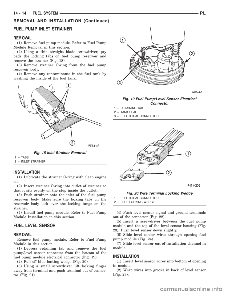
(2) Using a thin straight blade screwdriver, pry
back the locking tabs on fuel pump reservoir and
remove the strainer (Fig. 18).
(3) Remove strainer O-ring from the fuel pump
reservoir body.
(4) Remove any contaminants in the fuel tank by
washing the inside of the fuel tank.
INSTALLATION
(1) Lubricate the strainer O-ring with clean engine
oil.
(2) Insert strainer O-ring into outlet of strainer so
that it sits evenly on the step inside the outlet.
(3) Push strainer onto the inlet of the fuel pump
reservoir body. Make sure the locking tabs on the
reservoir body lock over the locking tangs on the
strainer.
(4) Install fuel pump module. Refer to Fuel Pump
Module Installation in this section.
FUEL LEVEL SENSOR
REMOVAL
Remove fuel pump module. Refer to Fuel Pump
Module in this section.
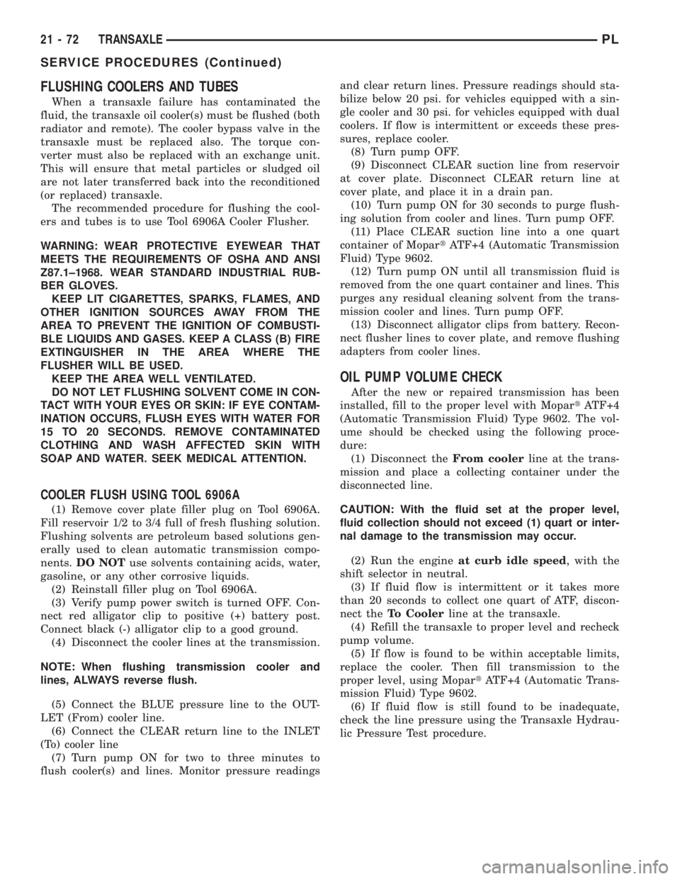
(1) Depress retaining tab and remove the fuel
pump/level sensor connector from the bottom of the
fuel pump module electrical connector (Fig. 19).
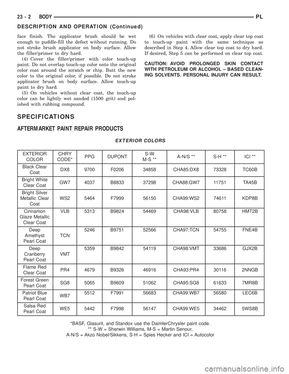
(2) Pull off blue locking wedge (Fig. 20).
(3) Using a small screwdriver lift locking finger
away from terminal and push terminal out of connec-
tor (Fig. 21).(4) Push level sensor signal and ground terminals
out of the connector (Fig. 22).
(5) Insert a screwdriver between the fuel pump
module and the top of the level sensor housing (Fig.
23). Push level sensor down slightly.
(6) Slide level sensor wires through opening fuel
pump module (Fig. 24).
(7) Slide level sensor out of installation channel in
module.
INSTALLATION
(1) Insert level sensor wires into bottom of opening
in module.
(2) Wrap wires into groove in back of level sensor
(Fig. 23).
Fig. 18 Inlet Strainer Removal
1±TABS
2 ± INLET STRAINER
Fig. 19 Fuel Pump/Level Sensor Electrical
Connector
1 ± RETAINING TAB
2 ± TANK SEAL
3 ± ELECTRICAL CONNECTOR
Fig. 20 Wire Terminal Locking Wedge
1 ± ELECTRICAL CONNECTOR
2 ± BLUE LOCKING WEDGE
14 - 14 FUEL SYSTEMPL
REMOVAL AND INSTALLATION (Continued)
Page 985 of 1285

FLUSHING COOLERS AND TUBES
When a transaxle failure has contaminated the
fluid, the transaxle oil cooler(s) must be flushed (both
radiator and remote). The cooler bypass valve in the
transaxle must be replaced also. The torque con-
verter must also be replaced with an exchange unit.
This will ensure that metal particles or sludged oil
are not later transferred back into the reconditioned
(or replaced) transaxle.
The recommended procedure for flushing the cool-
ers and tubes is to use Tool 6906A Cooler Flusher.
WARNING: WEAR PROTECTIVE EYEWEAR THAT
MEETS THE REQUIREMENTS OF OSHA AND ANSI
Z87.1±1968. WEAR STANDARD INDUSTRIAL RUB-
BER GLOVES.
KEEP LIT CIGARETTES, SPARKS, FLAMES, AND
OTHER IGNITION SOURCES AWAY FROM THE
AREA TO PREVENT THE IGNITION OF COMBUSTI-
BLE LIQUIDS AND GASES. KEEP A CLASS (B) FIRE
EXTINGUISHER IN THE AREA WHERE THE
FLUSHER WILL BE USED.
KEEP THE AREA WELL VENTILATED.
DO NOT LET FLUSHING SOLVENT COME IN CON-
TACT WITH YOUR EYES OR SKIN: IF EYE CONTAM-
INATION OCCURS, FLUSH EYES WITH WATER FOR
15 TO 20 SECONDS. REMOVE CONTAMINATED
CLOTHING AND WASH AFFECTED SKIN WITH
SOAP AND WATER. SEEK MEDICAL ATTENTION.
COOLER FLUSH USING TOOL 6906A
(1) Remove cover plate filler plug on Tool 6906A.
Fill reservoir 1/2 to 3/4 full of fresh flushing solution.
Flushing solvents are petroleum based solutions gen-
erally used to clean automatic transmission compo-
nents.DO NOTuse solvents containing acids, water,
gasoline, or any other corrosive liquids.
(2) Reinstall filler plug on Tool 6906A.
(3) Verify pump power switch is turned OFF. Con-
nect red alligator clip to positive (+) battery post.
Connect black (-) alligator clip to a good ground.
(4) Disconnect the cooler lines at the transmission.
NOTE: When flushing transmission cooler and
lines, ALWAYS reverse flush.
(5) Connect the BLUE pressure line to the OUT-
LET (From) cooler line.
(6) Connect the CLEAR return line to the INLET
(To) cooler line
(7) Turn pump ON for two to three minutes to
flush cooler(s) and lines. Monitor pressure readingsand clear return lines. Pressure readings should sta-
bilize below 20 psi. for vehicles equipped with a sin-
gle cooler and 30 psi. for vehicles equipped with dual
coolers. If flow is intermittent or exceeds these pres-
sures, replace cooler.
(8) Turn pump OFF.
(9) Disconnect CLEAR suction line from reservoir
at cover plate. Disconnect CLEAR return line at
cover plate, and place it in a drain pan.
(10) Turn pump ON for 30 seconds to purge flush-
ing solution from cooler and lines. Turn pump OFF.
(11) Place CLEAR suction line into a one quart
container of MopartATF+4 (Automatic Transmission
Fluid) Type 9602.
(12) Turn pump ON until all transmission fluid is
removed from the one quart container and lines. This
purges any residual cleaning solvent from the trans-
mission cooler and lines. Turn pump OFF.
(13) Disconnect alligator clips from battery. Recon-
nect flusher lines to cover plate, and remove flushing
adapters from cooler lines.
OIL PUMP VOLUME CHECK
After the new or repaired transmission has been
installed, fill to the proper level with MopartATF+4
(Automatic Transmission Fluid) Type 9602. The vol-
ume should be checked using the following proce-
dure:
(1) Disconnect theFrom coolerline at the trans-
mission and place a collecting container under the
disconnected line.
CAUTION: With the fluid set at the proper level,
fluid collection should not exceed (1) quart or inter-
nal damage to the transmission may occur.
(2) Run the engineat curb idle speed, with the
shift selector in neutral.
(3) If fluid flow is intermittent or it takes more
than 20 seconds to collect one quart of ATF, discon-
nect theTo Coolerline at the transaxle.
(4) Refill the transaxle to proper level and recheck
pump volume.
(5) If flow is found to be within acceptable limits,
replace the cooler. Then fill transmission to the
proper level, using MopartATF+4 (Automatic Trans-
mission Fluid) Type 9602.
(6) If fluid flow is still found to be inadequate,
check the line pressure using the Transaxle Hydrau-
lic Pressure Test procedure.
21 - 72 TRANSAXLEPL
SERVICE PROCEDURES (Continued)
Page 1119 of 1285

face finish. The applicator brush should be wet
enough to puddle-fill the defect without running. Do
not stroke brush applicator on body surface. Allow
the filler/primer to dry hard.
(4) Cover the filler/primer with color touch-up
paint. Do not overlap touch-up color onto the original
color coat around the scratch or chip. Butt the new
color to the original color, if possible. Do not stroke
applicator brush on body surface. Allow touch-up
paint to dry hard.
(5) On vehicles without clear coat, the touch-up
color can be lightly wet sanded (1500 grit) and pol-
ished with rubbing compound.(6) On vehicles with clear coat, apply clear top coat
to touch-up paint with the same technique as
described in Step 4. Allow clear top coat to dry hard.
If desired, Step 5 can be performed on clear top coat.
CAUTION: AVOID PROLONGED SKIN CONTACT
WITH PETROLEUM OR ALCOHOL ± BASED CLEAN-
ING SOLVENTS. PERSONAL INJURY CAN RESULT.
SPECIFICATIONS
AFTERMARKET PAINT REPAIR PRODUCTS
EXTERIOR COLORS
EXTERIOR
COLORCHRY
CODE*PPG DUPONTS-W
M-S **A-N/S ** S-H ** ICI **
Black Clear
CoatDX8 9700 F0206 34858 CHA85:DX8 73328 TC60B
Bright White
Clear CoatGW7 4037 B8833 37298 CHA88:GW7 11751 TA45B
Bright Silver
Metallic Clear
CoatWS2 5464 F7999 56150 CHA99:WS2 74611 KDP8B
Cinnamon
Glaze Metallic
Clear CoatVLB 5313 B9824 54469 CHA98:VLB 80758 HMT2B
Deep
Amethyst
Pearl CoatTCN5246 B9751 52566 CHA97:TCN 54755 FNE4B
Deep
Cranberry
Pearl CoatVMT5359 B9842 54119 CHA98:VMT 33686 GJX2B
Flame Red
Clear CoatPR4 4679 B9326 46916 CHA93:PR4 30116 2NNGB
Forest Green
Pearl CoatSG8 5065 B9609 51062 CHA95:SG8 61633 7MR8B
Patriot Blue
Pearl CoatWB75512 F7991 56683 CHA99:WB7 56580 LEC6B
Salsa Red
Pearl CoatWE5 5442 F7998 56147 CHA99:WE5 34462 5WS8B
*BASF, Glasurit, and Standox use the DaimlerChrysler paint code.
** S-W = Sherwin Williams, M-S = Martin Senour,
A-N/S = Akzo Nobel/Sikkens, S-H = Spies Hecker and ICI = Autocolor
23 - 2 BODYPL
DESCRIPTION AND OPERATION (Continued)
Page 1250 of 1285

Then allow the system to evacuate an additional 10
minutes.
(3) Close all valves. Turn off and disconnect the
vacuum pump.
(4) The refrigerant system is prepared to be
charged with refrigerant.
R-134a REFRIGERANT
This vehicle uses a refrigerant called R-134a. It is
a non-toxic, non-flammable, clear colorless liquefied
gas.
R-134a refrigerant is not compatible with R-12
refrigerant in an air conditioning system. Even a
small amount of R-12 in a R-134a system could cause
compressor failure, refrigerant oil to sludge and/or
poor performance.Never add any other type of
refrigerant to a system designed to use R-134a
refrigerant. System failure will occur.
The high pressure service port is located on the
ffilter/drier. The low pressure service port is located
on the suction line near the strut tower.
When servicing a system, it is required that an air
conditioning charging recovery/recycling machine be
used (Fig. 18). Contact an automotive service equip-
ment supplier for proper equipment. Refer to the
operating instructions provided with the equipment
for proper operation.
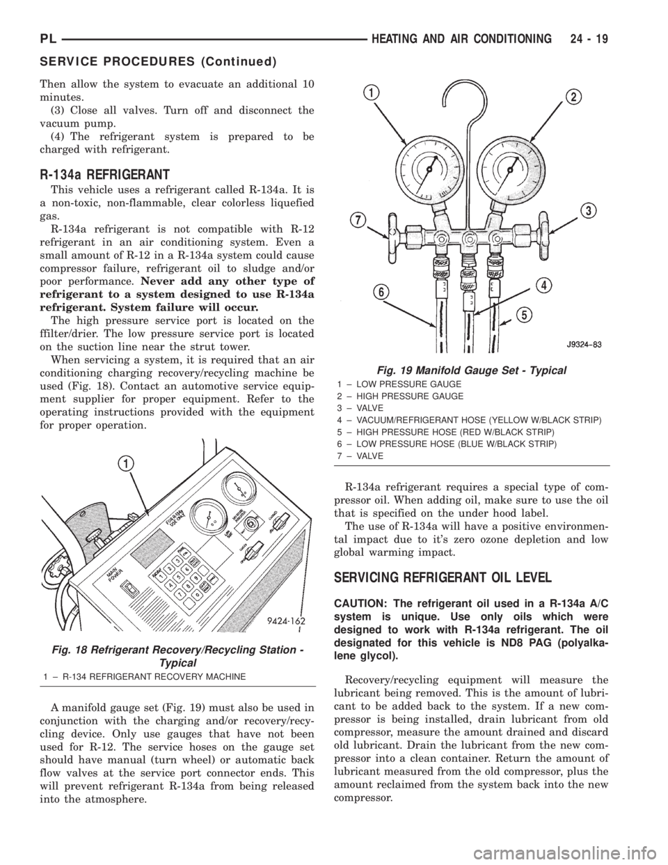
A manifold gauge set (Fig. 19) must also be used in
conjunction with the charging and/or recovery/recy-
cling device. Only use gauges that have not been
used for R-12. The service hoses on the gauge set
should have manual (turn wheel) or automatic back
flow valves at the service port connector ends. This
will prevent refrigerant R-134a from being released
into the atmosphere.R-134a refrigerant requires a special type of com-
pressor oil. When adding oil, make sure to use the oil
that is specified on the under hood label.
The use of R-134a will have a positive environmen-
tal impact due to it's zero ozone depletion and low
global warming impact.
SERVICING REFRIGERANT OIL LEVEL
CAUTION: The refrigerant oil used in a R-134a A/C
system is unique. Use only oils which were
designed to work with R-134a refrigerant. The oil
designated for this vehicle is ND8 PAG (polyalka-
lene glycol).
Recovery/recycling equipment will measure the
lubricant being removed. This is the amount of lubri-
cant to be added back to the system. If a new com-
pressor is being installed, drain lubricant from old
compressor, measure the amount drained and discard
old lubricant. Drain the lubricant from the new com-
pressor into a clean container. Return the amount of
lubricant measured from the old compressor, plus the
amount reclaimed from the system back into the new
compressor.
Fig. 18 Refrigerant Recovery/Recycling Station -
Typical
1 ± R-134 REFRIGERANT RECOVERY MACHINE
Fig. 19 Manifold Gauge Set - Typical
1 ± LOW PRESSURE GAUGE
2 ± HIGH PRESSURE GAUGE
3 ± VALVE
4 ± VACUUM/REFRIGERANT HOSE (YELLOW W/BLACK STRIP)
5 ± HIGH PRESSURE HOSE (RED W/BLACK STRIP)
6 ± LOW PRESSURE HOSE (BLUE W/BLACK STRIP)
7 ± VALVE
PLHEATING AND AIR CONDITIONING 24 - 19
SERVICE PROCEDURES (Continued)