2000 DODGE NEON fold seats
[x] Cancel search: fold seatsPage 82 of 1285

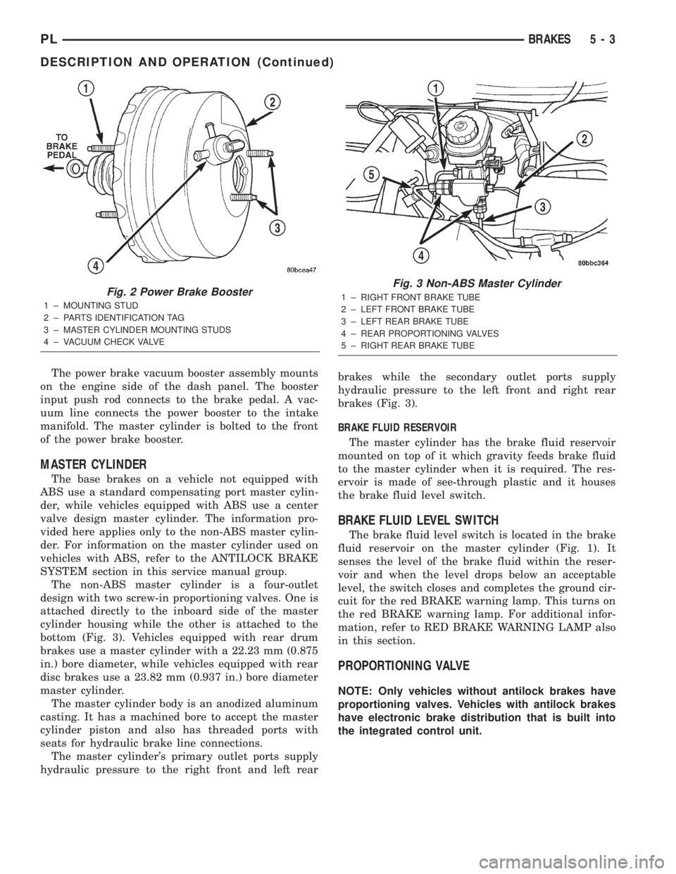
The power brake vacuum booster assembly mounts
on the engine side of the dash panel. The booster
input push rod connects to the brake pedal. A vac-
uum line connects the power booster to the intake
manifold. The master cylinder is bolted to the front
of the power brake booster.
MASTER CYLINDER
The base brakes on a vehicle not equipped with
ABS use a standard compensating port master cylin-
der, while vehicles equipped with ABS use a center
valve design master cylinder. The information pro-
vided here applies only to the non-ABS master cylin-
der. For information on the master cylinder used on
vehicles with ABS, refer to the ANTILOCK BRAKE
SYSTEM section in this service manual group.
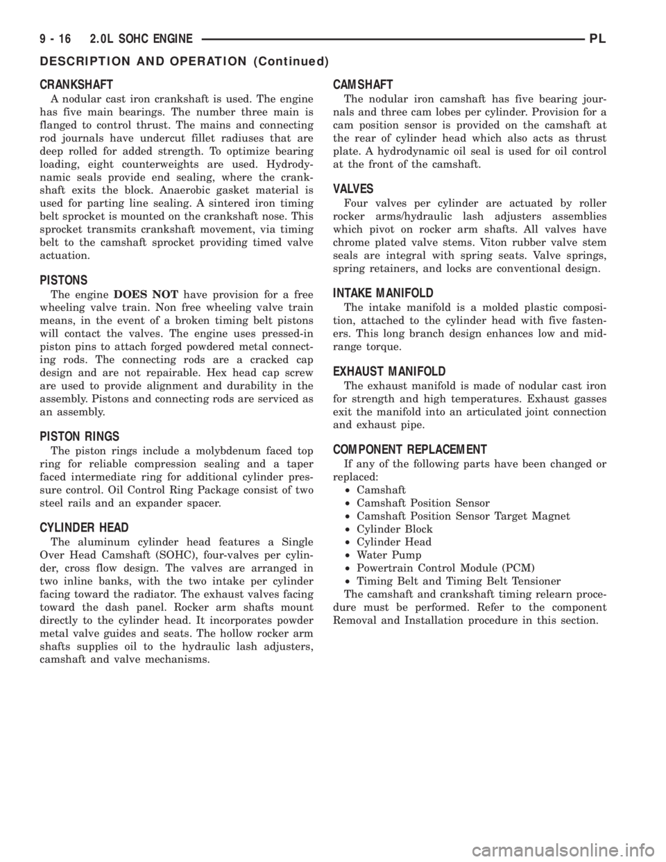
The non-ABS master cylinder is a four-outlet
design with two screw-in proportioning valves. One is
attached directly to the inboard side of the master
cylinder housing while the other is attached to the
bottom (Fig. 3). Vehicles equipped with rear drum
brakes use a master cylinder with a 22.23 mm (0.875
in.) bore diameter, while vehicles equipped with rear
disc brakes use a 23.82 mm (0.937 in.) bore diameter
master cylinder.
The master cylinder body is an anodized aluminum
casting. It has a machined bore to accept the master
cylinder piston and also has threaded ports with
seats for hydraulic brake line connections.
The master cylinder's primary outlet ports supply
hydraulic pressure to the right front and left rearbrakes while the secondary outlet ports supply
hydraulic pressure to the left front and right rear
brakes (Fig. 3).
BRAKE FLUID RESERVOIR
The master cylinder has the brake fluid reservoir
mounted on top of it which gravity feeds brake fluid
to the master cylinder when it is required. The res-
ervoir is made of see-through plastic and it houses
the brake fluid level switch.
BRAKE FLUID LEVEL SWITCH
The brake fluid level switch is located in the brake
fluid reservoir on the master cylinder (Fig. 1). It
senses the level of the brake fluid within the reser-
voir and when the level drops below an acceptable
level, the switch closes and completes the ground cir-
cuit for the red BRAKE warning lamp. This turns on
the red BRAKE warning lamp. For additional infor-
mation, refer to RED BRAKE WARNING LAMP also
in this section.
PROPORTIONING VALVE
NOTE: Only vehicles without antilock brakes have
proportioning valves. Vehicles with antilock brakes
have electronic brake distribution that is built into
the integrated control unit.
Fig. 2 Power Brake Booster
1 ± MOUNTING STUD
2 ± PARTS IDENTIFICATION TAG
3 ± MASTER CYLINDER MOUNTING STUDS
4 ± VACUUM CHECK VALVE
Fig. 3 Non-ABS Master Cylinder
1 ± RIGHT FRONT BRAKE TUBE
2 ± LEFT FRONT BRAKE TUBE
3 ± LEFT REAR BRAKE TUBE
4 ± REAR PROPORTIONING VALVES
5 ± RIGHT REAR BRAKE TUBE
PLBRAKES 5 - 3
DESCRIPTION AND OPERATION (Continued)
Page 739 of 1285

CRANKSHAFT
A nodular cast iron crankshaft is used. The engine
has five main bearings. The number three main is
flanged to control thrust. The mains and connecting
rod journals have undercut fillet radiuses that are
deep rolled for added strength. To optimize bearing
loading, eight counterweights are used. Hydrody-
namic seals provide end sealing, where the crank-
shaft exits the block. Anaerobic gasket material is
used for parting line sealing. A sintered iron timing
belt sprocket is mounted on the crankshaft nose. This
sprocket transmits crankshaft movement, via timing
belt to the camshaft sprocket providing timed valve
actuation.
PISTONS
The engineDOES NOThave provision for a free
wheeling valve train. Non free wheeling valve train
means, in the event of a broken timing belt pistons
will contact the valves. The engine uses pressed-in
piston pins to attach forged powdered metal connect-
ing rods. The connecting rods are a cracked cap
design and are not repairable. Hex head cap screw
are used to provide alignment and durability in the
assembly. Pistons and connecting rods are serviced as
an assembly.
PISTON RINGS
The piston rings include a molybdenum faced top
ring for reliable compression sealing and a taper
faced intermediate ring for additional cylinder pres-
sure control. Oil Control Ring Package consist of two
steel rails and an expander spacer.
CYLINDER HEAD
The aluminum cylinder head features a Single
Over Head Camshaft (SOHC), four-valves per cylin-
der, cross flow design. The valves are arranged in
two inline banks, with the two intake per cylinder
facing toward the radiator. The exhaust valves facing
toward the dash panel. Rocker arm shafts mount
directly to the cylinder head. It incorporates powder
metal valve guides and seats. The hollow rocker arm
shafts supplies oil to the hydraulic lash adjusters,
camshaft and valve mechanisms.
CAMSHAFT
The nodular iron camshaft has five bearing jour-
nals and three cam lobes per cylinder. Provision for a
cam position sensor is provided on the camshaft at
the rear of cylinder head which also acts as thrust
plate. A hydrodynamic oil seal is used for oil control
at the front of the camshaft.
VALVES
Four valves per cylinder are actuated by roller
rocker arms/hydraulic lash adjusters assemblies
which pivot on rocker arm shafts. All valves have
chrome plated valve stems. Viton rubber valve stem
seals are integral with spring seats. Valve springs,
spring retainers, and locks are conventional design.
INTAKE MANIFOLD
The intake manifold is a molded plastic composi-
tion, attached to the cylinder head with five fasten-
ers. This long branch design enhances low and mid-
range torque.
EXHAUST MANIFOLD
The exhaust manifold is made of nodular cast iron
for strength and high temperatures. Exhaust gasses
exit the manifold into an articulated joint connection
and exhaust pipe.
COMPONENT REPLACEMENT
If any of the following parts have been changed or
replaced:
²Camshaft
²Camshaft Position Sensor
²Camshaft Position Sensor Target Magnet
²Cylinder Block
²Cylinder Head
²Water Pump
²Powertrain Control Module (PCM)
²Timing Belt and Timing Belt Tensioner
The camshaft and crankshaft timing relearn proce-
dure must be performed. Refer to the component
Removal and Installation procedure in this section.
9 - 16 2.0L SOHC ENGINEPL
DESCRIPTION AND OPERATION (Continued)
Page 1173 of 1285

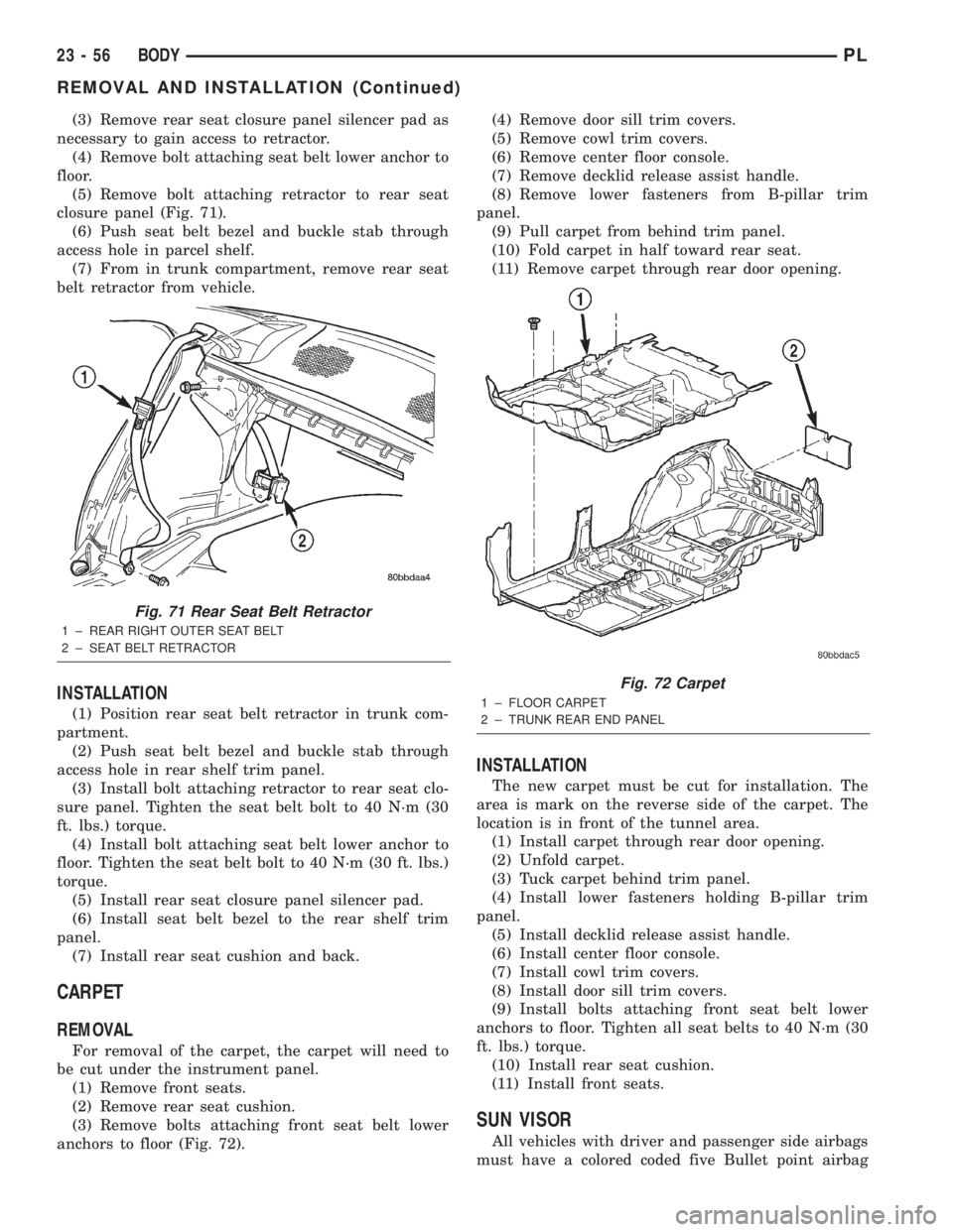
(3) Remove rear seat closure panel silencer pad as
necessary to gain access to retractor.
(4) Remove bolt attaching seat belt lower anchor to
floor.
(5) Remove bolt attaching retractor to rear seat
closure panel (Fig. 71).
(6) Push seat belt bezel and buckle stab through
access hole in parcel shelf.
(7) From in trunk compartment, remove rear seat
belt retractor from vehicle.
INSTALLATION
(1) Position rear seat belt retractor in trunk com-
partment.
(2) Push seat belt bezel and buckle stab through
access hole in rear shelf trim panel.
(3) Install bolt attaching retractor to rear seat clo-
sure panel. Tighten the seat belt bolt to 40 N´m (30
ft. lbs.) torque.
(4) Install bolt attaching seat belt lower anchor to
floor. Tighten the seat belt bolt to 40 N´m (30 ft. lbs.)
torque.
(5) Install rear seat closure panel silencer pad.
(6) Install seat belt bezel to the rear shelf trim
panel.
(7) Install rear seat cushion and back.
CARPET
REMOVAL
For removal of the carpet, the carpet will need to
be cut under the instrument panel.
(1) Remove front seats.
(2) Remove rear seat cushion.
(3) Remove bolts attaching front seat belt lower
anchors to floor (Fig. 72).(4) Remove door sill trim covers.
(5) Remove cowl trim covers.
(6) Remove center floor console.
(7) Remove decklid release assist handle.
(8) Remove lower fasteners from B-pillar trim
panel.
(9) Pull carpet from behind trim panel.
(10) Fold carpet in half toward rear seat.
(11) Remove carpet through rear door opening.
INSTALLATION
The new carpet must be cut for installation. The
area is mark on the reverse side of the carpet. The
location is in front of the tunnel area.
(1) Install carpet through rear door opening.
(2) Unfold carpet.
(3) Tuck carpet behind trim panel.
(4) Install lower fasteners holding B-pillar trim
panel.
(5) Install decklid release assist handle.
(6) Install center floor console.
(7) Install cowl trim covers.
(8) Install door sill trim covers.
(9) Install bolts attaching front seat belt lower
anchors to floor. Tighten all seat belts to 40 N´m (30
ft. lbs.) torque.
(10) Install rear seat cushion.
(11) Install front seats.
SUN VISOR
All vehicles with driver and passenger side airbags
must have a colored coded five Bullet point airbag
Fig. 71 Rear Seat Belt Retractor
1 ± REAR RIGHT OUTER SEAT BELT
2 ± SEAT BELT RETRACTOR
Fig. 72 Carpet
1 ± FLOOR CARPET
2 ± TRUNK REAR END PANEL
23 - 56 BODYPL
REMOVAL AND INSTALLATION (Continued)