2000 DODGE NEON oil additives
[x] Cancel search: oil additivesPage 181 of 1285

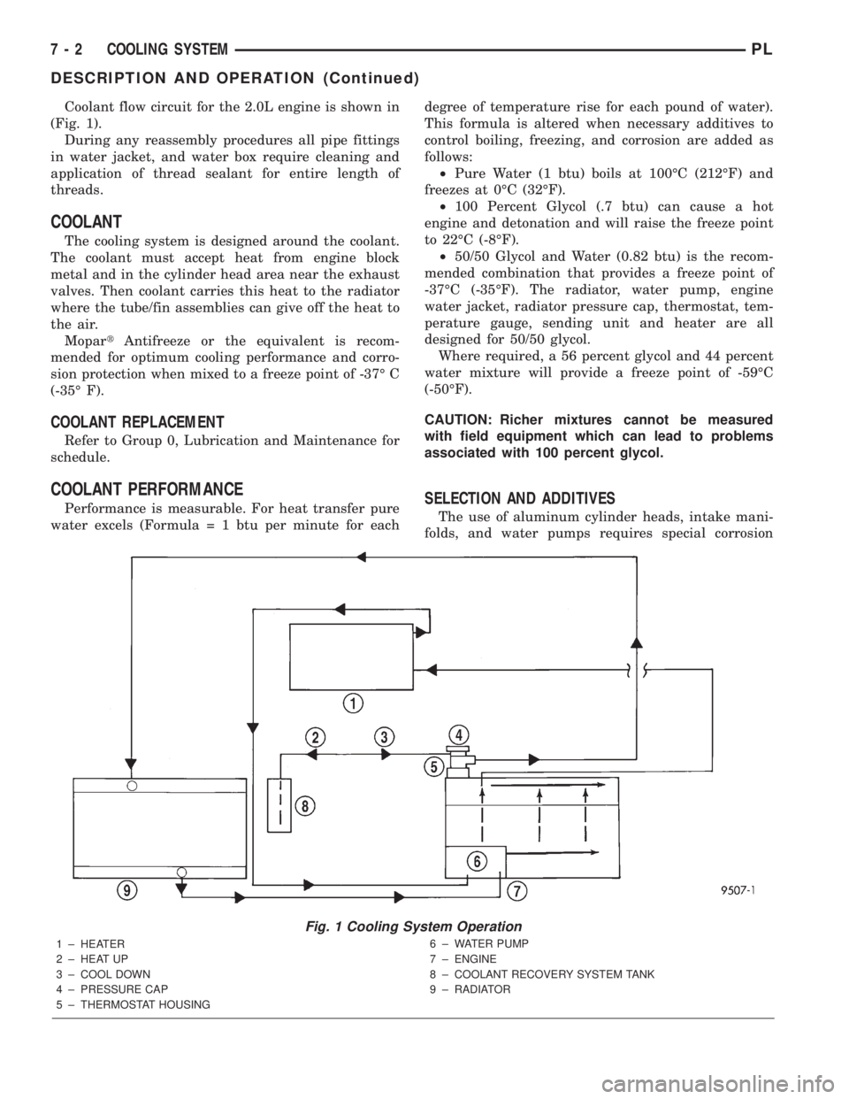
Coolant flow circuit for the 2.0L engine is shown in
(Fig. 1).
During any reassembly procedures all pipe fittings
in water jacket, and water box require cleaning and
application of thread sealant for entire length of
threads.
COOLANT
The cooling system is designed around the coolant.
The coolant must accept heat from engine block
metal and in the cylinder head area near the exhaust
valves. Then coolant carries this heat to the radiator
where the tube/fin assemblies can give off the heat to
the air.
MopartAntifreeze or the equivalent is recom-
mended for optimum cooling performance and corro-
sion protection when mixed to a freeze point of -37É C
(-35É F).
COOLANT REPLACEMENT
Refer to Group 0, Lubrication and Maintenance for
schedule.
COOLANT PERFORMANCE
Performance is measurable. For heat transfer pure
water excels (Formula = 1 btu per minute for eachdegree of temperature rise for each pound of water).
This formula is altered when necessary additives to
control boiling, freezing, and corrosion are added as
follows:
²Pure Water (1 btu) boils at 100ÉC (212ÉF) and
freezes at 0ÉC (32ÉF).
²100 Percent Glycol (.7 btu) can cause a hot
engine and detonation and will raise the freeze point
to 22ÉC (-8ÉF).
²50/50 Glycol and Water (0.82 btu) is the recom-
mended combination that provides a freeze point of
-37ÉC (-35ÉF). The radiator, water pump, engine
water jacket, radiator pressure cap, thermostat, tem-
perature gauge, sending unit and heater are all
designed for 50/50 glycol.
Where required, a 56 percent glycol and 44 percent
water mixture will provide a freeze point of -59ÉC
(-50ÉF).
CAUTION: Richer mixtures cannot be measured
with field equipment which can lead to problems
associated with 100 percent glycol.SELECTION AND ADDITIVES
The use of aluminum cylinder heads, intake mani-
folds, and water pumps requires special corrosion
Fig. 1 Cooling System Operation
1 ± HEATER
2 ± HEAT UP
3 ± COOL DOWN
4 ± PRESSURE CAP
5 ± THERMOSTAT HOUSING6 ± WATER PUMP
7 ± ENGINE
8 ± COOLANT RECOVERY SYSTEM TANK
9 ± RADIATOR
7 - 2 COOLING SYSTEMPL
DESCRIPTION AND OPERATION (Continued)
Page 915 of 1285

ferential case transfers torque from the ring gear to the
drive axles by means of differential side gears.
The NV T350 (A-578) transaxle internal components
can only be serviced by separating the case halves.
CAUTION: The transaxle output shaft is serviced as
a unit. No disassembly and reassembly is possible.
Damage to the transaxle may result.
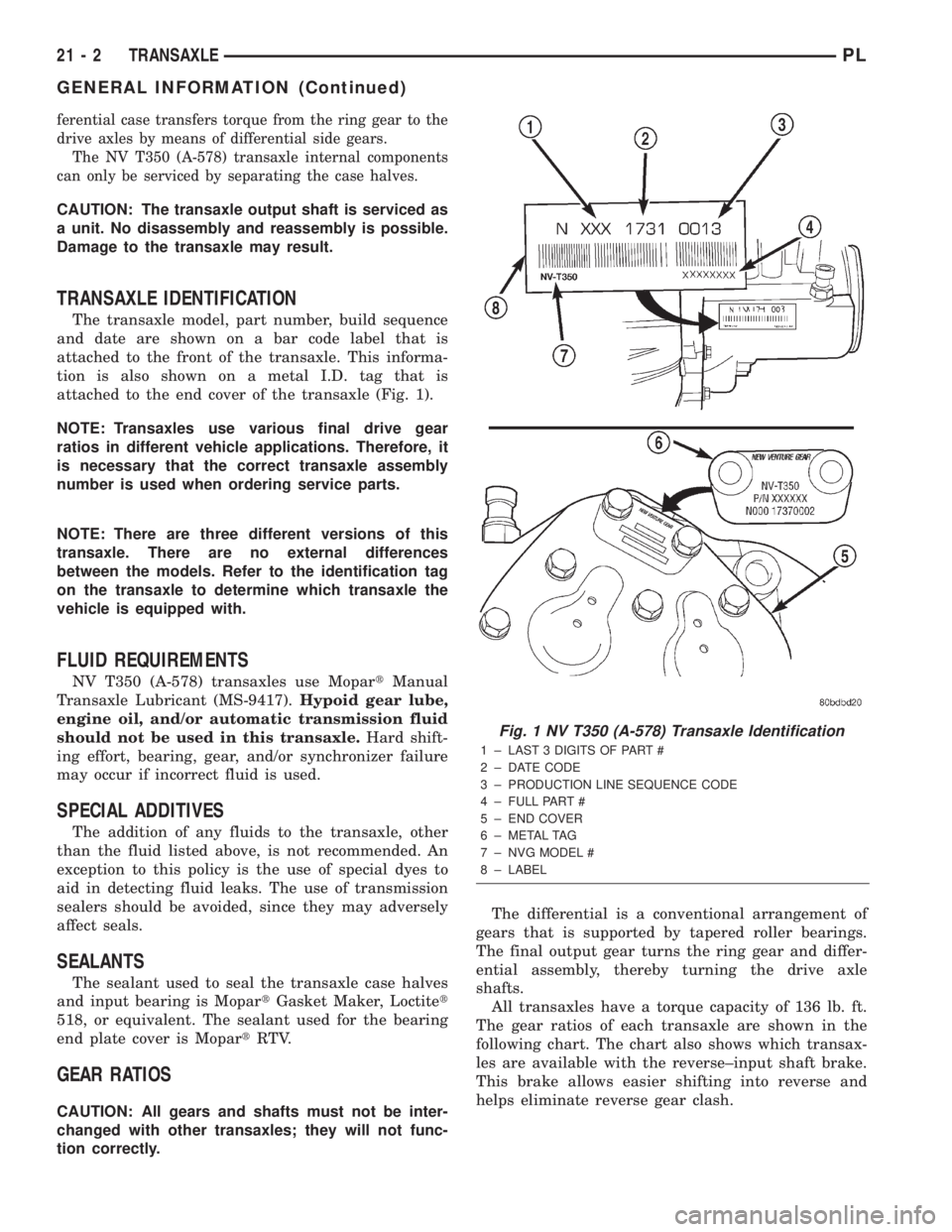
TRANSAXLE IDENTIFICATION
The transaxle model, part number, build sequence
and date are shown on a bar code label that is
attached to the front of the transaxle. This informa-
tion is also shown on a metal I.D. tag that is
attached to the end cover of the transaxle (Fig. 1).
NOTE: Transaxles use various final drive gear
ratios in different vehicle applications. Therefore, it
is necessary that the correct transaxle assembly
number is used when ordering service parts.
NOTE: There are three different versions of this
transaxle. There are no external differences
between the models. Refer to the identification tag
on the transaxle to determine which transaxle the
vehicle is equipped with.
FLUID REQUIREMENTS
NV T350 (A-578) transaxles use MopartManual
Transaxle Lubricant (MS-9417).Hypoid gear lube,
engine oil, and/or automatic transmission fluid
should not be used in this transaxle.Hard shift-
ing effort, bearing, gear, and/or synchronizer failure
may occur if incorrect fluid is used.
SPECIAL ADDITIVES
The addition of any fluids to the transaxle, other
than the fluid listed above, is not recommended. An
exception to this policy is the use of special dyes to
aid in detecting fluid leaks. The use of transmission
sealers should be avoided, since they may adversely
affect seals.
SEALANTS
The sealant used to seal the transaxle case halves
and input bearing is MopartGasket Maker, Loctitet
518, or equivalent. The sealant used for the bearing
end plate cover is MopartRTV.
GEAR RATIOS
CAUTION: All gears and shafts must not be inter-
changed with other transaxles; they will not func-
tion correctly.The differential is a conventional arrangement of
gears that is supported by tapered roller bearings.
The final output gear turns the ring gear and differ-
ential assembly, thereby turning the drive axle
shafts.
All transaxles have a torque capacity of 136 lb. ft.
The gear ratios of each transaxle are shown in the
following chart. The chart also shows which transax-
les are available with the reverse±input shaft brake.
This brake allows easier shifting into reverse and
helps eliminate reverse gear clash.
Fig. 1 NV T350 (A-578) Transaxle Identification
1 ± LAST 3 DIGITS OF PART #
2 ± DATE CODE
3 ± PRODUCTION LINE SEQUENCE CODE
4 ± FULL PART #
5 ± END COVER
6 ± METAL TAG
7 ± NVG MODEL #
8 ± LABEL
21 - 2 TRANSAXLEPL
GENERAL INFORMATION (Continued)
Page 968 of 1285

GENERAL INFORMATION
IN VEHICLE SERVICE
The following components are serviceable in the
vehicle without transaxle removal:
²Valve Body Assembly
²Converter Clutch Solenoid
²Governor
²Vehicle Speed Sensor & Pinion
²Park/Neutral & Back-up Lamp Switch
²Transfer Gears and Transfer Shaft
²Low/Reverse Servo
²Kickdown Servo
²Accumulator
FLUID REQUIREMENTS
NOTE: The transmission and differential have a
common oil sump with an opening between the
two.
TRANSMISSION/DIFFERENTIAL
MopartATF+4 (Automatic Transmission Fluid
Type 9602) is required in this transaxle. Substitute
fluids must meet fluid specification MS-9602.
FLUID ADDITIVES
Chrysler Corporation strongly recommends against
the addition of any fluids to the transmission, other
than those automatic transmission fluids listed
above. Exceptions to this policy are the use of special
dyes to aid in detecting fluid leaks.
Various ªspecialº additives and supplements exist
that claim to improve shift feel/quality and converter
clutch operation, inhibit overheating, oxidation, var-
nish and sludge. These claims have not been sup-
ported to Chrysler's satisfaction and these additives
must not be used. The use of transmission ªsealersº
should also be avoided, since they may adversely
affect the integrity of tranmission seals.
DESCRIPTION AND OPERATION
31TH GENERAL INFORMATION
NOTE: Safety goggles should be worn at all times
when working on these transaxles.
This transaxle combines torque converter, three
speed transmission, final drive gearing, and differen-
tial into a front wheel drive system.
NOTE: Transaxle operation requirements are differ-
ent for each vehicle and engine combination. Some
internal parts will be different to provide for this.Therefore, when replacing parts, refer to the seven
digit part number stamped on rear of the transaxle
oil pan flange.
Within this transaxle, there are three primary
areas:
(1) Main center line plus valve body.
(2) Transfer shaft center line (includes governor
and parking sprag).
(3) Differential center line.
Center distances between the main rotating parts
in these three areas are held precise to maintain a
low noise level.
The torque converter, transaxle area, and differen-
tial are housed in an integral aluminum die casting.
The differential oil sump is common with the
transaxle sump. Separate filling of the differen-
tial is NOT necessary.
The torque converter is attached to the crankshaft
through a flexible driving plate. Cooling of the con-
verter is accomplished by circulating the transaxle
fluid through a remote cooler. There are two types of
coolers used. An oil-to-water type cooler located in
the radiator side tank and/or an oil-to-air heat
exchanger. The torque converter assembly is a sealed
unit that cannot be disassembled.
The transaxle fluid is filtered by an internal filter
attached to the lower side of the valve body assembly.
Engine torque is transmitted to the torque con-
verter and then through the input shaft to multiple-
disc clutches in the transaxle. The power flow
depends on the application of the clutches and bands.
Refer to Elements in Use Chart in Diagnosis and
Tests section.
The transaxle consists of:
²Two multiple-disc clutches
²An overrunning clutch
²Two servos
²A hydraulic accumulator
²Two bands
²Two planetary gear sets
This provides three forward ratios and a reverse
ratio. The common sun gear of the planetary gear
sets is connected to the front clutch by a driving
shell. The driving shell is splined to the sun gear and
front clutch retainer. The hydraulic system consists
of an oil pump and a single valve body which con-
tains all of the valves except the governor valves.
The transaxle sump and differential sump are both
vented through the dipstick. Output torque from the
main center line is delivered through helical gears to
the transfer shaft. This gear set is a factor in the
transaxle final drive (axle) ratio. The shaft also car-
ries the governor and parking sprag. An integral heli-
cal gear on the transfer shaft drives the differential
ring gear.
PLTRANSAXLE 21 - 55
Page 984 of 1285

(4) Clean the oil pan and magnet. Reinstall pan
using new Mopar Silicone Adhesive sealant. Tighten
oil pan bolts to 19 N´m (165 in. lbs.).
(5) Pour four quarts of MopartATF+4 (Automatic
Transmission Fluid) Type 9602 through the dipstick
opening.
(6) Start engine and allow to idle for at least one
minute. Then, with parking and service brakes
applied, move selector lever momentarily to each
position, ending in the park or neutral position.
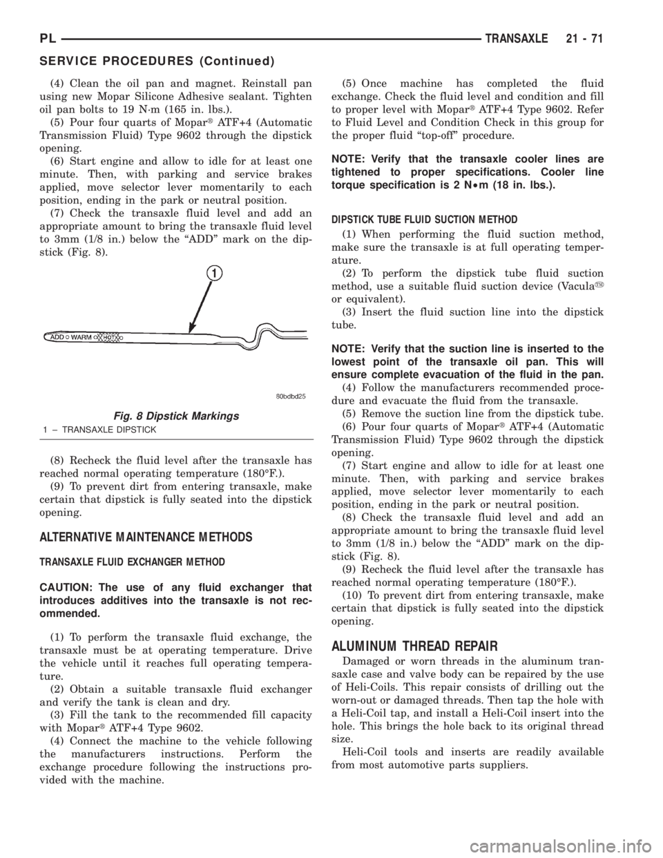
(7) Check the transaxle fluid level and add an
appropriate amount to bring the transaxle fluid level
to 3mm (1/8 in.) below the ªADDº mark on the dip-
stick (Fig. 8).
(8) Recheck the fluid level after the transaxle has
reached normal operating temperature (180ÉF.).
(9) To prevent dirt from entering transaxle, make
certain that dipstick is fully seated into the dipstick
opening.
ALTERNATIVE MAINTENANCE METHODS
TRANSAXLE FLUID EXCHANGER METHOD
CAUTION: The use of any fluid exchanger that
introduces additives into the transaxle is not rec-
ommended.
(1) To perform the transaxle fluid exchange, the
transaxle must be at operating temperature. Drive
the vehicle until it reaches full operating tempera-
ture.
(2) Obtain a suitable transaxle fluid exchanger
and verify the tank is clean and dry.
(3) Fill the tank to the recommended fill capacity
with MopartATF+4 Type 9602.
(4) Connect the machine to the vehicle following
the manufacturers instructions. Perform the
exchange procedure following the instructions pro-
vided with the machine.(5) Once machine has completed the fluid
exchange. Check the fluid level and condition and fill
to proper level with MopartATF+4 Type 9602. Refer
to Fluid Level and Condition Check in this group for
the proper fluid ªtop-offº procedure.
NOTE: Verify that the transaxle cooler lines are
tightened to proper specifications. Cooler line
torque specification is 2 N²m (18 in. lbs.).
DIPSTICK TUBE FLUID SUCTION METHOD
(1) When performing the fluid suction method,
make sure the transaxle is at full operating temper-
ature.
(2) To perform the dipstick tube fluid suction
method, use a suitable fluid suction device (Vaculay
or equivalent).
(3) Insert the fluid suction line into the dipstick
tube.
NOTE: Verify that the suction line is inserted to the
lowest point of the transaxle oil pan. This will
ensure complete evacuation of the fluid in the pan.
(4) Follow the manufacturers recommended proce-
dure and evacuate the fluid from the transaxle.
(5) Remove the suction line from the dipstick tube.
(6) Pour four quarts of MopartATF+4 (Automatic
Transmission Fluid) Type 9602 through the dipstick
opening.
(7) Start engine and allow to idle for at least one
minute. Then, with parking and service brakes
applied, move selector lever momentarily to each
position, ending in the park or neutral position.
(8) Check the transaxle fluid level and add an
appropriate amount to bring the transaxle fluid level
to 3mm (1/8 in.) below the ªADDº mark on the dip-
stick (Fig. 8).
(9) Recheck the fluid level after the transaxle has
reached normal operating temperature (180ÉF.).
(10) To prevent dirt from entering transaxle, make
certain that dipstick is fully seated into the dipstick
opening.
ALUMINUM THREAD REPAIR
Damaged or worn threads in the aluminum tran-
saxle case and valve body can be repaired by the use
of Heli-Coils. This repair consists of drilling out the
worn-out or damaged threads. Then tap the hole with
a Heli-Coil tap, and install a Heli-Coil insert into the
hole. This brings the hole back to its original thread
size.
Heli-Coil tools and inserts are readily available
from most automotive parts suppliers.
Fig. 8 Dipstick Markings
1 ± TRANSAXLE DIPSTICK
PLTRANSAXLE 21 - 71
SERVICE PROCEDURES (Continued)