2000 DODGE NEON traction control
[x] Cancel search: traction controlPage 81 of 1285
DESCRIPTION AND OPERATION
BASE BRAKE SYSTEM OPERATION
When a vehicle needs to be stopped, the driver
applies the brake pedal. The brake pedal pushes the
input rod of the power brake booster into the booster.
The booster uses vacuum to ease pedal effort as force
is transferred through the booster to the master cyl-
inder. The booster's output rod pushes in the master
cylinder's primary and secondary pistons applying
hydraulic pressure through the chassis brake tubes
and proportioning valves (rear only) to the brakes at
each tire and wheel assembly.
Front disc brakes control the braking of the front
wheels; rear braking is controlled by rear drum
brakes as standard equipment. Rear disc brakes and
an antilock brake system (ABS) with traction control
are optional.
The hydraulic brake system is diagonally split on
both the non-antilock and antilock braking systems.
This means the left front and right rear brakes are
on one hydraulic circuit and the right front and left
rear are on the other.
Vehicles equipped with the optional antilock brake
system (ABS) use a system designated Mark 20e.
This system shares most base brake hardware used
on vehicles without ABS. A vehicle equipped with
ABS, however, uses a different master cylinder and
brake tubes. Also included in the ABS system is an
integrated control unit (ICU) and four wheel speed
sensors. These components are described in detail in
the ANTILOCK BRAKE SYSTEM section in this
group of the service manual. All vehicles with ABS
come standard with four-wheel-disc brakes and trac-
tion control.
The parking brakes are hand-operated. When
applied, the parking brake lever pulls on cables that
actuate brake shoes at each rear wheel. The parking
brake lever has an automatic adjusting feature that
takes up any excessive slack in the parking brake
cable system.
BASE BRAKE SYSTEM COMPONENTS
BRAKE PEDAL
A suspended-type brake pedal is used on this vehi-
cle. The pedal pivots on a shaft mounted in the pedal
support bracket under the instrument panel. The
pedal connects to the power brake booster input rod
and pushes it in when the pedal is applied.
The brake pedal and it's pad are serviceable sepa-
rately.
POWER BRAKE BOOSTER
There are two different power brake booster
designs, although externally they appear the same.
All vehicles use a 205 mm tandem diaphragm power
brake booster. The two boosters are internally tuned
differently depending on whether the vehicle is
equipped with the standard front disc/rear drum
brake combination or the optional front disc/rear disc
(four-wheel disc) brake combination. If the power
brake booster requires replacement, be sure it is
replaced with the correct part.
The power brake booster can be identified by the
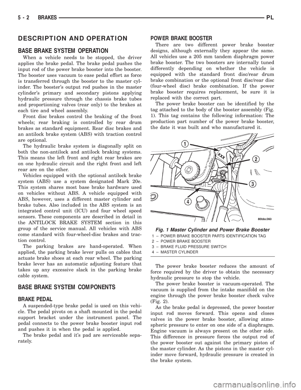
tag attached to the body of the booster assembly (Fig.
1). This tag contains the following information: The
production part number of the power brake booster,
the date it was built and who manufactured it.
The power brake booster reduces the amount of
force required by the driver to obtain the necessary
hydraulic pressure to stop the vehicle.
The power brake booster is vacuum-operated. The
vacuum is supplied from the intake manifold on the
engine through the power brake booster check valve
(Fig. 2).
As the brake pedal is depressed, the power booster
input rod moves forward. This opens and closes
valves in the power brake booster, allowing atmo-
spheric pressure to enter on one side of a diaphragm.
Engine vacuum is always present on the other side.
This difference in pressure forces the output rod of
the power booster out against the primary piston of
the master cylinder. As the pistons in the master cyl-
inder move forward, hydraulic pressure is created in
the brake system.
Fig. 1 Master Cylinder and Power Brake Booster
1 ± POWER BRAKE BOOSTER PARTS IDENTIFICATION TAG
2 ± POWER BRAKE BOOSTER
3 ± BRAKE FLUID PRESSURE SWITCH
4 ± MASTER CYLINDER
5 - 2 BRAKESPL
Page 144 of 1285
ANTILOCK BRAKE SYSTEM
TABLE OF CONTENTS
page page
DESCRIPTION AND OPERATION
ANTILOCK BRAKE SYSTEM OPERATION......65
ANTILOCK BRAKE SYSTEM COMPONENTS....66
ELECTRONIC BRAKE DISTRIBUTION.........69
TRACTION CONTROL SYSTEM..............70
HYDRAULIC CIRCUITS AND VALVE
OPERATION...........................71
DIAGNOSIS AND TESTING
SERVICE WARNINGS AND CAUTIONS........74
ABS GENERAL DIAGNOSTICS INFORMATION . . 74
ABS WIRING DIAGRAM INFORMATION........74
ABS VEHICLE TEST DRIVE.................74
ABS ELECTRONIC DIAGNOSIS..............75
TONE WHEEL...........................76
BRAKE FLUID CONTAMINATION.............76
SERVICE PROCEDURES
BRAKE FLUID LEVEL CHECKING............77ANTILOCK BRAKE SYSTEM BLEEDING.......77
MASTER CYLINDER BLEEDING.............77
REMOVAL AND INSTALLATION
SERVICE WARNINGS AND CAUTIONS........78
MASTER CYLINDER......................78
INTEGRATED CONTROL UNIT...............79
WHEEL SPEED SENSOR (FRONT)...........81
WHEEL SPEED SENSOR (REAR)............83
DISASSEMBLY AND ASSEMBLY
INTEGRATED CONTROL UNIT...............84
SPECIFICATIONS
TONE WHEEL RUNOUT....................85
WHEEL SPEED SENSOR-TO-TONE WHEEL
CLEARANCE...........................85
BRAKE FASTENER TORQUE
SPECIFICATIONS.......................85
DESCRIPTION AND OPERATION
ANTILOCK BRAKE SYSTEM OPERATION
This section covers the physical and operational
descriptions, and the on-car service procedures for
the Mark 20e Antilock Brake System (ABS) with
traction control. It is the only antilock brake system
available on this vehicle.
The purpose of the antilock brake system is to pre-
vent wheel lockup under braking conditions on virtu-
ally any type of road surface. Antilock braking is
desirable because a vehicle that is stopped without
locking the wheels retains directional stability and
some steering capability. This allows the driver to
retain greater control of the vehicle during braking.
The traction control system reduces wheel slip and
maintains traction at the driving speeds below 56
kph (35 mph) when road conditions call for traction
assistance. Refer to TRACTION CONTROL SYSTEM
in this section for more information.
Vehicles equipped with ABS use electronic brake
distribution (EBD) to balance front-to-rear braking
when the brakes are applied in the partial braking
range. Refer to ELECTRONIC BRAKE DISTRIBU-
TION in this section for more information.
There are a few performance characteristics of the
Mark 20e Antilock Brake System that may at first
seem abnormal, but in fact are normal. These char-
acteristics are described below.
NORMAL BRAKING
Under normal braking conditions, the ABS func-
tions the same as a standard base brake system with
a diagonally split master cylinder and conventional
vacuum assist.
ABS BRAKING
ABS operation is available at all vehicle speeds
above 3±5 mph. If a wheel locking tendency is
detected during a brake application, the brake sys-
tem enters the ABS mode. During ABS braking,
hydraulic pressure in the four wheel circuits is mod-
ulated to prevent any wheel from locking. Each
wheel circuit is designed with a set of electric sole-
noids to allow modulation, although for vehicle sta-
bility, both rear wheel solenoids receive the same
electrical signal. Wheel lockup may be perceived at
the very end of an ABS stop and is considered nor-
mal.
During an ABS stop, the brakes hydraulic system
is still diagonally split. However, the brake system
pressure is further split into four control channels.
During antilock operation of the vehicle's brake sys-
tem, the wheels are controlled independently and are
on separate control channels.
The system can build, hold and release pressure at
each wheel, depending on signals generated by the
wheel speed sensors (WSS) at each wheel and
received at the controller antilock brake (CAB).
PLBRAKES 5 - 65
Page 146 of 1285
The ABS with traction control ICU consists of the
following components: the CAB, eight (build/decay)
solenoid valves (four inlet valves and four outlet
valves), two hydraulic shuttle valves, two traction
control valves, valve block, fluid accumulators, a
pump, and an electric pump/motor.
The replaceable components of the ICU are the
HCU and the CAB. No attempt should be made to
service any components found inside of the HCU or
CAB.
CONTROLLER ANTILOCK BRAKE (CAB)
The controller antilock brake (CAB) is a micropro-
cessor-based device which monitors the ABS system
during normal braking and controls it when the vehi-
cle is in an ABS stop. The CAB is mounted to the
bottom of the HCU (Fig. 2). The CAB uses a 25-way
electrical connector on the vehicle wiring harness.
The power source for the CAB is through the ignition
switch in the RUN or ON position. The CAB is on
the PCI bus.
The primary functions of the (CAB) are to:
(1) monitor the antilock brake system for proper
operation.
(2) detect wheel locking or wheel slipping tenden-
cies by monitoring the speed of all four wheels of the
vehicle.
(3) control fluid modulation to the wheel brakes
while the system is in an ABS mode or the traction
control system is activated.
(4) store diagnostic information.
(5) provide communication to the DRB scan tool
while in diagnostic mode.
The CAB constantly monitors the antilock brake
system for proper operation. If the CAB detects a
fault, it will send a message to the mechanical instu-
ment cluster (MIC) instructing it to turn on the
amber ABS warning lamp and disable the antilock
braking system. The normal base braking system will
remain operational.
The CAB continuously monitors the speed of each
wheel through the signals generated by the wheel
speed sensors to determine if any wheel is beginning
to lock. When a wheel locking tendency is detected,
the CAB commands the CAB command coils to actu-
ate. The CAB command coils then open and close the
valves in the HCU that modulate brake fluid pres-
sure in some or all of the hydraulic circuits. The CAB
continues to control pressure in individual hydraulic
circuits until a locking tendency is no longer present.
The CAB contains a self-diagnostic program that
monitors the antilock brake system for system faults.
When a fault is detected, the amber ABS warning
lamp is turned on and the fault diagnostic trouble
code (DTC) is then stored in a diagnostic program
memory. These DTC's will remain in the CAB mem-
ory even after the ignition has been turned off. The
DTC's can be read and cleared from the CAB mem-
ory by a technician using the DRB scan tool. If not
cleared with a DRB scan tool, the fault occurrence
and DTC will be automatically cleared from the CAB
memory after the identical fault has not been seen
during the next 3,500 miles of vehicle operation.
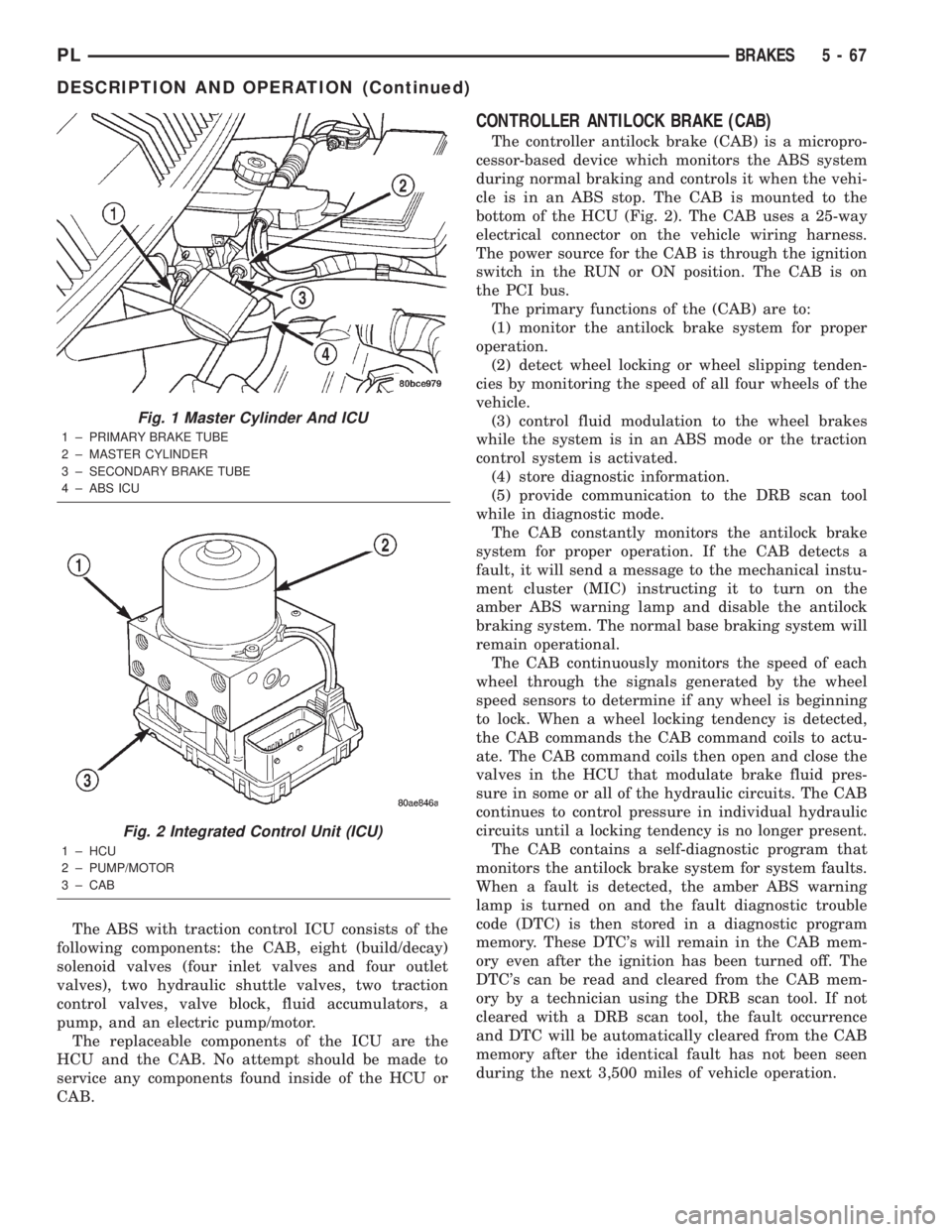
Fig. 1 Master Cylinder And ICU
1 ± PRIMARY BRAKE TUBE
2 ± MASTER CYLINDER
3 ± SECONDARY BRAKE TUBE
4 ± ABS ICU
Fig. 2 Integrated Control Unit (ICU)
1 ± HCU
2 ± PUMP/MOTOR
3 ± CAB
PLBRAKES 5 - 67
DESCRIPTION AND OPERATION (Continued)
Page 147 of 1285
CONTROLLER ANTILOCK BRAKE INPUTS
²wheel speed sensors (four)
²stop lamp switch
²ignition switch
²system relay voltage
²ground
²traction control lamp
²diagnostic communication (PCI)
CONTROLLER ANTILOCK BRAKE OUTPUTS
²amber ABS warning lamp actuation (through
MIC)
²red BRAKE warning lamp actuation (through
MIC)
²traction control lamp actuation (through MIC)
²diagnostic communication. (PCI)
HYDRAULIC CONTROL UNIT (HCU)
The hydraulic control unit (HCU) is mounted to
the CAB as part of the ICU (Fig. 2). The HCU con-
trols the flow of brake fluid to the brakes using a
series of valves and accumulators. A pump/motor is
mounted on the HCU to supply build pressure to the
brakes during an ABS stop.
VALVES AND SOLENOIDS
The valve block contains four inlet valves and four
outlet solenoid valves. The inlet valves are spring-
loaded in the open position and the outlet valves are
spring-loaded in the closed position during normal
braking. The fluid is allowed to flow from the master
cylinder to the wheel brakes.
During an ABS stop, these valves cycle to maintain
the proper slip ratio for each wheel. The inlet valve
closes preventing further pressure increase and the
outlet valve opens to provide a path from the wheel
brake to the HCU accumulators and pump/motor.
This releases (decays) pressure from the wheel brake,
thus releasing the wheel from excessive slippage.
Once the wheel is no longer slipping, the outlet valve
is closed and the inlet valve is opened to reapply
(build) pressure.
There are four other valves in the HCU. These four
remaining valves are used for traction control. Two
traction control (TC) valves, mounted in the HCU
valve block, are normally in the open position and
close only when the traction control is applied. There
are also two shuttle valves which control pressure
return to the master cylinder under ABS and traction
control conditions.
These TC valves are used to isolate the rear (non-
driving) wheels of the vehicle from the hydraulic
pressure that the HCU pump/motor is sending to the
front (driving) wheels when traction control is being
applied. The rear brakes need to be isolated from the
master cylinder when traction control is beingapplied so the rear wheels do not drag. For more
information on the TC and shuttle valves, see TRAC-
TION CONTROL SYSTEM in this section.
BRAKE FLUID ACCUMULATORS
There are two fluid accumulators in the HCU: one
for the primary hydraulic circuit, and one for the sec-
ondary hydraulic circuit. Each hydraulic circuit uses
a 3 cc accumulator.
The fluid accumulators temporarily store brake
fluid that is removed from the wheel brakes during
an ABS cycle. This stored fluid is used by the pump/
motor to provide build pressure for the brake hydrau-
lic system. When the antilock stop is complete, the
accumulators are drained by the pump/motor.
There are two noise dampening chambers in the
HCU on this vehicle equipped with traction control.
PUMP/MOTOR
There are two pump assemblies in the HCU: one
for the primary hydraulic circuit, and one for the sec-
ondary hydraulic circuit. Both pumps are driven by a
common electric motor (Fig. 2). This DC-type motor
is integral to the HCU and is controlled by the CAB.
The pump/motor provides the extra amount of
brake fluid needed during antilock braking. Brake
fluid is released to the accumulators when the outlet
valve is opened during an antilock stop. The pump
mechanism consists of two opposing pistons operated
by an eccentric camshaft. In operation, these pistons
are used to purge fluid from the accumulators back
into the master cylinder circuits. When the antilock
stop is complete, the pump/motor drains the accumu-
lators.
The pump motor is also used to build pressure
when the system goes into traction control mode. For
more information, refer to TRACTION CONTROL
SYSTEM in this section.
The CAB may turn on the pump/motor when an
antilock stop is detected. The pump/motor continues
to run during the antilock stop and is turned off after
the stop is complete. Under some conditions, the
pump/motor runs to drain the accumulators during
the next drive-off.
The pump/motor is not a serviceable item; if it
requires replacement, the HCU must be replaced.
ABS FUSES
The ABS fuse and the ABS pump/motor fuse are
located in the power distribution center (PDC). Refer
to the sticker on the inside of the PDC cover for the
location of these fuses. The PDC is located on the
driver's side of the engine compartment between the
back of the battery and the brake master cylinder.
The CAB fuse can be found in the fuse junction
block under the instrument panel.
5 - 68 BRAKESPL
DESCRIPTION AND OPERATION (Continued)
Page 149 of 1285
the rear brake circuit is pulsed. This allows fluid to
enter the low pressure accumulator (LPA) in the
hydraulic control unit (HCU) resulting in a drop in
fluid pressure to the rear brakes. In order to increase
the rear brake pressure, the outlet valve is switched
off and the inlet valve is pulsed. This increases the
pressure to the rear brakes. This back-and-forth pro-
cess will continue until the required slip difference is
obtained. At the end of EBD braking (brakes
released) the fluid in the LPA drains back to themaster cylinder by switching on the outlet valve and
draining through the inlet valve check valve. At the
same time the inlet valve is switched on in case of
another brake application.
The EBD will remain functional during many ABS
fault modes. If both the red BRAKE, and amber ABS
warning lamps are illuminated, the EBD may not be
functioning.
TRACTION CONTROL SYSTEM
Traction control reduces wheel slip and maintains
traction at the driving wheels at speeds below 56 kph
(35 mph) when road surfaces are slippery. The trac-
tion control system reduces wheel slip by braking the
wheel that is losing traction.
The CAB monitors wheel speed. During accelera-
tion, if the CAB detects front (drive) wheel slip and
the brakes are not applied, the CAB enters traction
control mode. Traction control operation proceeds in
the following order:
(1) Close the normally open traction control (TC)
valves.
(2) Start the pump/motor and supply volume and
pressure to the front (drive) hydraulic circuit. (The
pump/motor runs continuously during traction con-
trol operation.)
(3) Open and close the build and decay solenoid
valves to maintain minimum wheel slip and maxi-
mum traction.
The cycling of the build and decay valves during
traction control is similar to that during antilock
braking, except the valves work to control wheel spin
by applying the brakes, whereas the ABS function is
to control wheel skid by releasing the brakes.
HYDRAULIC SHUTTLE VALVES
Two pressure relief shuttle valves allow pressure
and volume to return to the master cylinder reservoir
when not consumed by the build and decay valves.
These valves are necessary because the pump/motor
supplies more volume than the system requires.
If the brakes are applied at anytime during a trac-
tion control cycle, the brake lamp switch triggers the
control module to switch off traction control.
TRACTION CONTROL FUNCTION LAMP
The traction control function lamp illuminates dur-
ing a traction control cycle, displaying TRAC on the
instrument panel.
The traction control system is enabled at each igni-
tion cycle. It may be turned off by depressing the
traction control switch button. The traction control
function lamp (TRAC OFF) illuminates immediately
upon depressing the button. Pressing this button
again, or turning off and restarting the vehicle will
enable the traction control system.
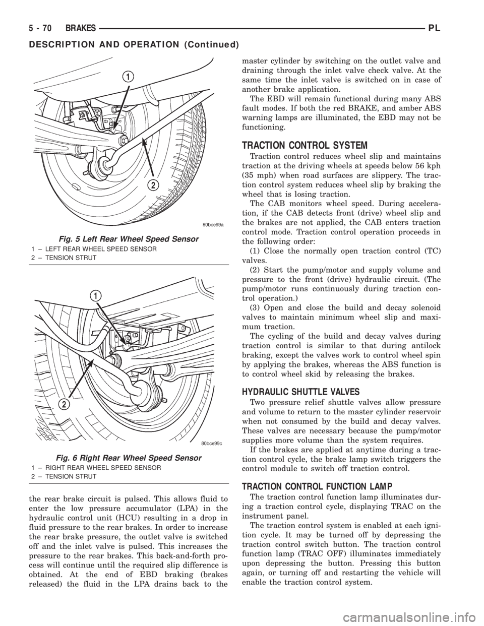
Fig. 5 Left Rear Wheel Speed Sensor
1 ± LEFT REAR WHEEL SPEED SENSOR
2 ± TENSION STRUT
Fig. 6 Right Rear Wheel Speed Sensor
1 ± RIGHT REAR WHEEL SPEED SENSOR
2 ± TENSION STRUT
5 - 70 BRAKESPL
DESCRIPTION AND OPERATION (Continued)
Page 150 of 1285
If the CAB calculates that the brake temperatures
are high, the traction control system becomes inoper-
ative until a time-out period has elapsed. During this
ªthermo-protection mode,º the traction control func-
tion lamp illuminates TRAC OFF; note that no trou-
ble code is registered.
HYDRAULIC CIRCUITS AND VALVE OPERATION
The hydraulic shuttle valves control the flow of
pressurized brake fluid to the wheel brakes during
the different modes of ABS braking. The following
paragraphs explain how this works. For purposes of
explanation only, it is assumed that only the right
front wheel is experiencing antilock braking; the fol-
lowing diagrams show only the right front wheel in
an antilock braking operation.
NORMAL BRAKING HYDRAULIC CIRCUIT,
SOLENOID VALVE, AND SHUTTLE VALVE
FUNCTION (ABS WITH TRACTION CONTROL)
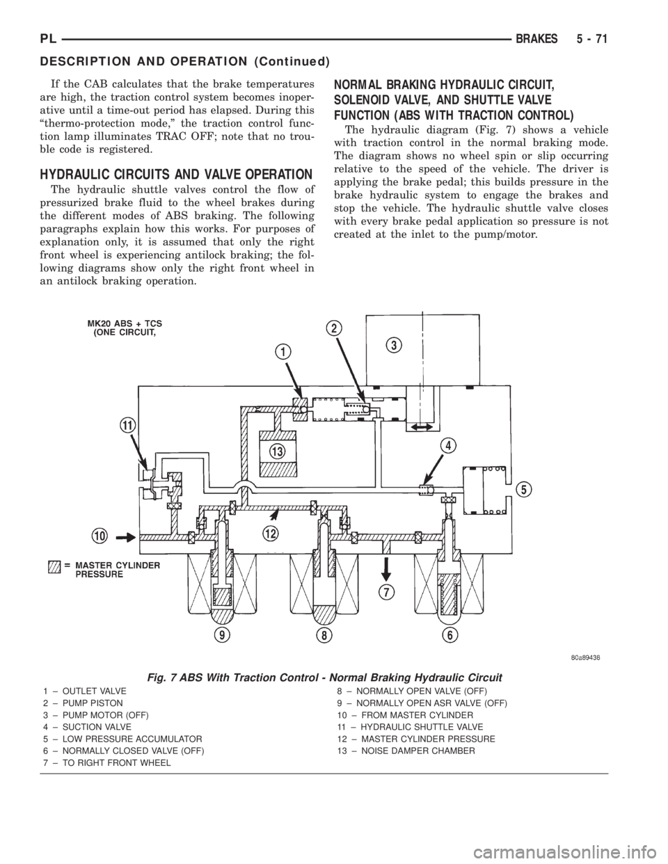
The hydraulic diagram (Fig. 7) shows a vehicle
with traction control in the normal braking mode.
The diagram shows no wheel spin or slip occurring
relative to the speed of the vehicle. The driver is
applying the brake pedal; this builds pressure in the
brake hydraulic system to engage the brakes and
stop the vehicle. The hydraulic shuttle valve closes
with every brake pedal application so pressure is not
created at the inlet to the pump/motor.
Fig. 7 ABS With Traction Control - Normal Braking Hydraulic Circuit
1 ± OUTLET VALVE
2 ± PUMP PISTON
3 ± PUMP MOTOR (OFF)
4 ± SUCTION VALVE
5 ± LOW PRESSURE ACCUMULATOR
6 ± NORMALLY CLOSED VALVE (OFF)
7 ± TO RIGHT FRONT WHEEL8 ± NORMALLY OPEN VALVE (OFF)
9 ± NORMALLY OPEN ASR VALVE (OFF)
10 ± FROM MASTER CYLINDER
11 ± HYDRAULIC SHUTTLE VALVE
12 ± MASTER CYLINDER PRESSURE
13 ± NOISE DAMPER CHAMBER
PLBRAKES 5 - 71
DESCRIPTION AND OPERATION (Continued)
Page 151 of 1285
ABS BRAKING HYDRAULIC CIRCUIT, SOLENOID
VALVE, AND SHUTTLE VALVE FUNCTION (ABS
WITH TRACTION CONTROL)
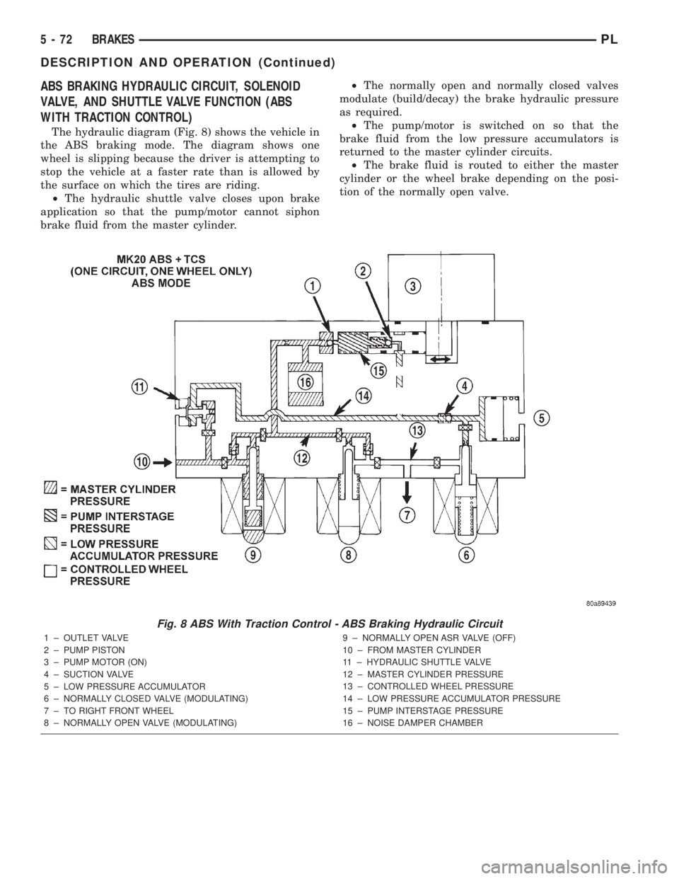
The hydraulic diagram (Fig. 8) shows the vehicle in
the ABS braking mode. The diagram shows one
wheel is slipping because the driver is attempting to
stop the vehicle at a faster rate than is allowed by
the surface on which the tires are riding.
²The hydraulic shuttle valve closes upon brake
application so that the pump/motor cannot siphon
brake fluid from the master cylinder.²The normally open and normally closed valves
modulate (build/decay) the brake hydraulic pressure
as required.
²The pump/motor is switched on so that the
brake fluid from the low pressure accumulators is
returned to the master cylinder circuits.
²The brake fluid is routed to either the master
cylinder or the wheel brake depending on the posi-
tion of the normally open valve.
Fig. 8 ABS With Traction Control - ABS Braking Hydraulic Circuit
1 ± OUTLET VALVE
2 ± PUMP PISTON
3 ± PUMP MOTOR (ON)
4 ± SUCTION VALVE
5 ± LOW PRESSURE ACCUMULATOR
6 ± NORMALLY CLOSED VALVE (MODULATING)
7 ± TO RIGHT FRONT WHEEL
8 ± NORMALLY OPEN VALVE (MODULATING)9 ± NORMALLY OPEN ASR VALVE (OFF)
10 ± FROM MASTER CYLINDER
11 ± HYDRAULIC SHUTTLE VALVE
12 ± MASTER CYLINDER PRESSURE
13 ± CONTROLLED WHEEL PRESSURE
14 ± LOW PRESSURE ACCUMULATOR PRESSURE
15 ± PUMP INTERSTAGE PRESSURE
16 ± NOISE DAMPER CHAMBER
5 - 72 BRAKESPL
DESCRIPTION AND OPERATION (Continued)
Page 152 of 1285
ABS TRACTION CONTROL HYDRAULIC CIRCUIT,
SOLENOID VALVE, AND SHUTTLE VALVE
FUNCTION (ABS WITH TRACTION CONTROL)
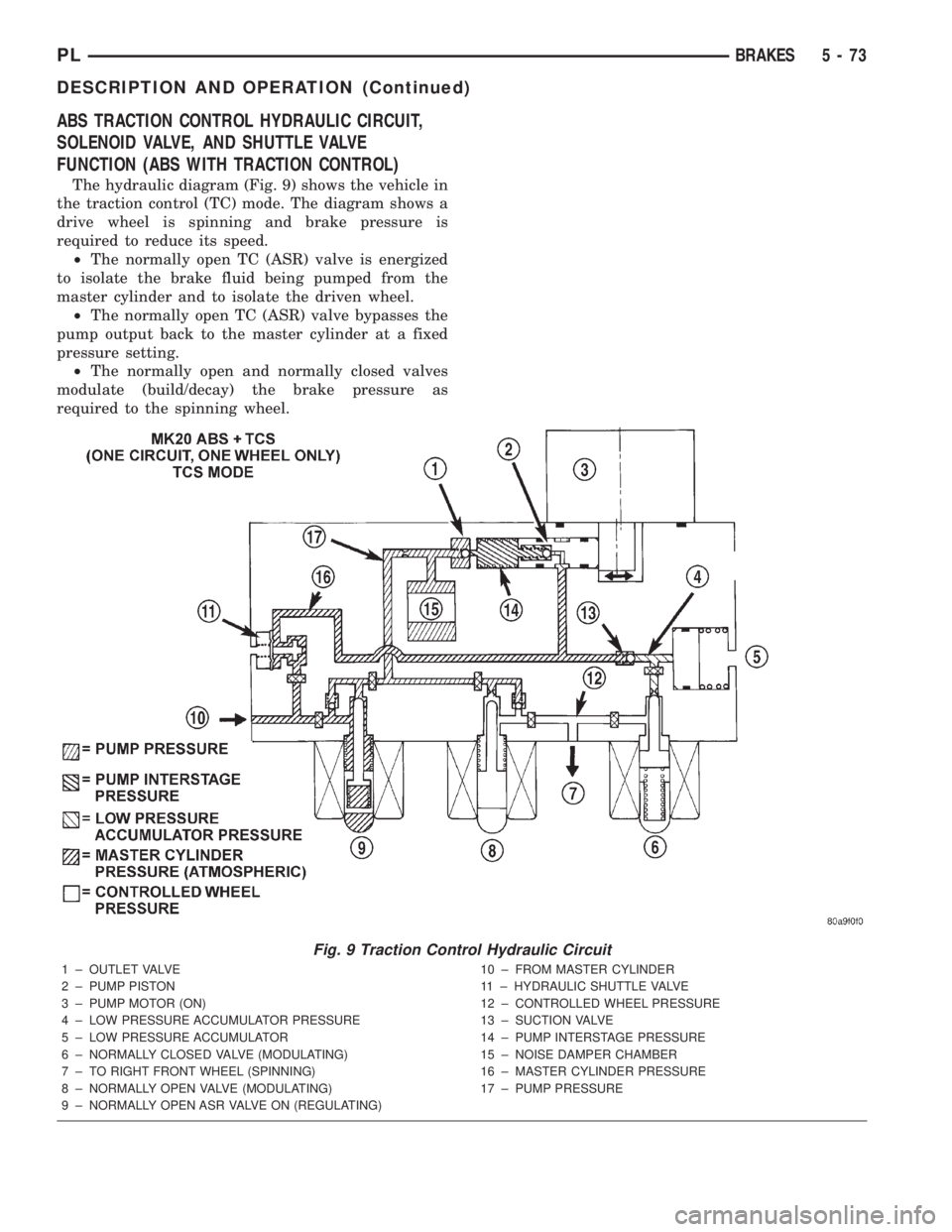
The hydraulic diagram (Fig. 9) shows the vehicle in
the traction control (TC) mode. The diagram shows a
drive wheel is spinning and brake pressure is
required to reduce its speed.
²The normally open TC (ASR) valve is energized
to isolate the brake fluid being pumped from the
master cylinder and to isolate the driven wheel.
²The normally open TC (ASR) valve bypasses the
pump output back to the master cylinder at a fixed
pressure setting.
²The normally open and normally closed valves
modulate (build/decay) the brake pressure as
required to the spinning wheel.
Fig. 9 Traction Control Hydraulic Circuit
1 ± OUTLET VALVE
2 ± PUMP PISTON
3 ± PUMP MOTOR (ON)
4 ± LOW PRESSURE ACCUMULATOR PRESSURE
5 ± LOW PRESSURE ACCUMULATOR
6 ± NORMALLY CLOSED VALVE (MODULATING)
7 ± TO RIGHT FRONT WHEEL (SPINNING)
8 ± NORMALLY OPEN VALVE (MODULATING)
9 ± NORMALLY OPEN ASR VALVE ON (REGULATING)10 ± FROM MASTER CYLINDER
11 ± HYDRAULIC SHUTTLE VALVE
12 ± CONTROLLED WHEEL PRESSURE
13 ± SUCTION VALVE
14 ± PUMP INTERSTAGE PRESSURE
15 ± NOISE DAMPER CHAMBER
16 ± MASTER CYLINDER PRESSURE
17 ± PUMP PRESSURE
PLBRAKES 5 - 73
DESCRIPTION AND OPERATION (Continued)