2000 DODGE NEON traction control
[x] Cancel search: traction controlPage 182 of 1285
protection. MopartAntifreeze or the equivalent is
recommended for best engine cooling without corro-
sion. When mixed only to a freeze point of -37ÉC
(-35ÉF) to -59ÉC (-50ÉF). If it looses color or becomes
contaminated, drain, flush, and replace with fresh
properly mixed solution.
COOLANT RECOVERY SYSTEM
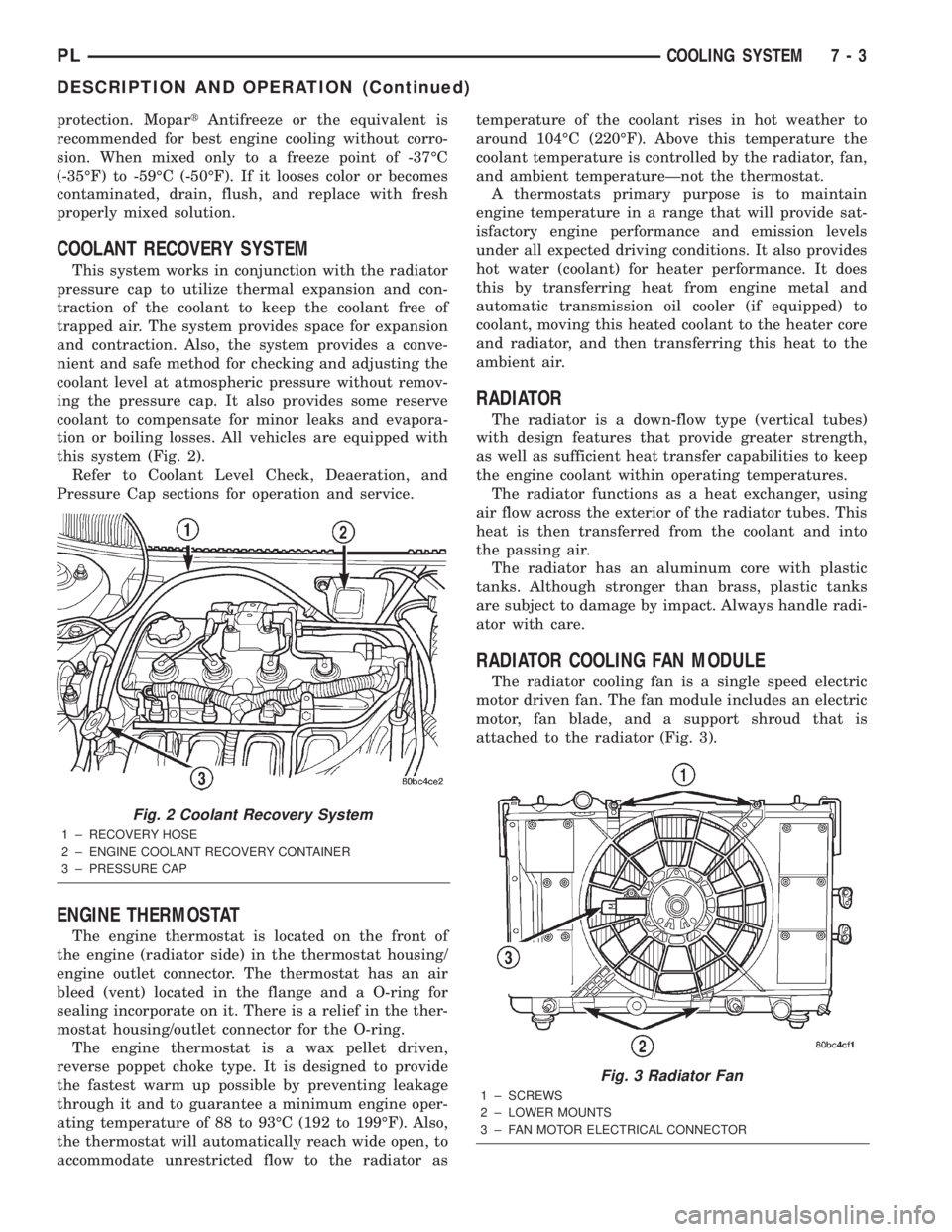
This system works in conjunction with the radiator
pressure cap to utilize thermal expansion and con-
traction of the coolant to keep the coolant free of
trapped air. The system provides space for expansion
and contraction. Also, the system provides a conve-
nient and safe method for checking and adjusting the
coolant level at atmospheric pressure without remov-
ing the pressure cap. It also provides some reserve
coolant to compensate for minor leaks and evapora-
tion or boiling losses. All vehicles are equipped with
this system (Fig. 2).
Refer to Coolant Level Check, Deaeration, and
Pressure Cap sections for operation and service.
ENGINE THERMOSTAT
The engine thermostat is located on the front of
the engine (radiator side) in the thermostat housing/
engine outlet connector. The thermostat has an air
bleed (vent) located in the flange and a O-ring for
sealing incorporate on it. There is a relief in the ther-
mostat housing/outlet connector for the O-ring.
The engine thermostat is a wax pellet driven,
reverse poppet choke type. It is designed to provide
the fastest warm up possible by preventing leakage
through it and to guarantee a minimum engine oper-
ating temperature of 88 to 93ÉC (192 to 199ÉF). Also,
the thermostat will automatically reach wide open, to
accommodate unrestricted flow to the radiator astemperature of the coolant rises in hot weather to
around 104ÉC (220ÉF). Above this temperature the
coolant temperature is controlled by the radiator, fan,
and ambient temperatureÐnot the thermostat.
A thermostats primary purpose is to maintain
engine temperature in a range that will provide sat-
isfactory engine performance and emission levels
under all expected driving conditions. It also provides
hot water (coolant) for heater performance. It does
this by transferring heat from engine metal and
automatic transmission oil cooler (if equipped) to
coolant, moving this heated coolant to the heater core
and radiator, and then transferring this heat to the
ambient air.
RADIATOR
The radiator is a down-flow type (vertical tubes)
with design features that provide greater strength,
as well as sufficient heat transfer capabilities to keep
the engine coolant within operating temperatures.
The radiator functions as a heat exchanger, using
air flow across the exterior of the radiator tubes. This
heat is then transferred from the coolant and into
the passing air.
The radiator has an aluminum core with plastic
tanks. Although stronger than brass, plastic tanks
are subject to damage by impact. Always handle radi-
ator with care.
RADIATOR COOLING FAN MODULE
The radiator cooling fan is a single speed electric
motor driven fan. The fan module includes an electric
motor, fan blade, and a support shroud that is
attached to the radiator (Fig. 3).
Fig. 2 Coolant Recovery System
1 ± RECOVERY HOSE
2 ± ENGINE COOLANT RECOVERY CONTAINER
3 ± PRESSURE CAP
Fig. 3 Radiator Fan
1 ± SCREWS
2 ± LOWER MOUNTS
3 ± FAN MOTOR ELECTRICAL CONNECTOR
PLCOOLING SYSTEM 7 - 3
DESCRIPTION AND OPERATION (Continued)
Page 248 of 1285
INSTRUMENT PANEL SYSTEMS
TABLE OF CONTENTS
page page
GENERAL INFORMATION
INTRODUCTION..........................1
DESCRIPTION AND OPERATION
HEADLAMP SWITCH......................2
INSTRUMENT CLUSTER....................2
WARNING AND INDICATOR LAMPS..........2
DIAGNOSIS AND TESTING
AIRBAG WARNING SYSTEM................2
BRAKE SYSTEM WARNING LAMP TEST.......2
INSTRUMENT CLUSTER LAMPS.............2
LOW OIL PRESSURE WARNING LAMP TEST...3
MULTIPLE/INDIVIDUAL GAUGES
INOPERATIVE..........................4
SERVICE PROCEDURES
INSTRUMENT CLUSTER SELF-DIAGNOSTICS...4
REMOVAL AND INSTALLATION
ACCESSORY SWITCH/POWER OUTLET
BEZEL................................4CENTER CONSOLE FLOOD LAMP............5
CIGAR LIGHTER / POWER OUTLET
ASSEMBLY.............................5
GLOVE BOX DOOR/BIN....................6
GLOVE BOX DOOR/BIN....................6
GLOVE BOX SWITCH/LAMP.................6
INSTRUMENT CLUSTER....................6
INSTRUMENT CLUSTER BEZEL..............6
INSTRUMENT CLUSTER LAMPS.............7
INSTRUMENT PANEL ASSEMBLY............7
INSTRUMENT PANEL CENTER BEZEL........10
INSTRUMENT PANEL END CAPS............10
INSTRUMENT PANEL TOP COVER...........10
LOWER INSTRUMENT PANEL COVER........10
LOWER STORAGE BIN....................10
STEERING COLUMN SHROUDS.............11
GENERAL INFORMATION
INTRODUCTION
The purpose of the dash gauges and indicator
lamps is to keep the driver informed about the oper-
ating condition of the vehicle. If an abnormal condi-
tion occurs, the driver is informed by indicator lamp.
The driver can seek service before damage occurs.
Indicator lamps use ON/OFF switch functions for
operation, while gauges use a sending unit or sensor.
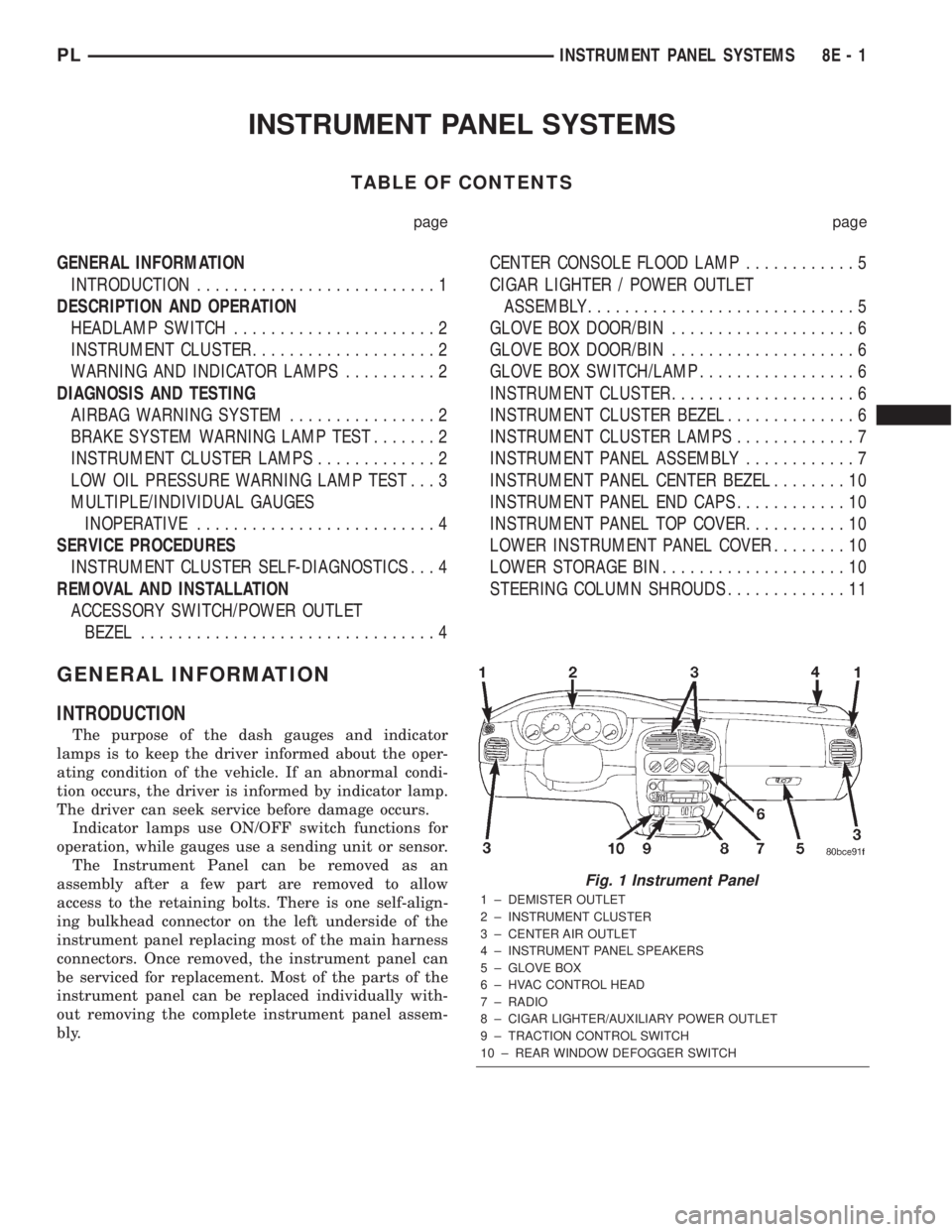
The Instrument Panel can be removed as an
assembly after a few part are removed to allow
access to the retaining bolts. There is one self-align-
ing bulkhead connector on the left underside of the
instrument panel replacing most of the main harness
connectors. Once removed, the instrument panel can
be serviced for replacement. Most of the parts of the
instrument panel can be replaced individually with-
out removing the complete instrument panel assem-
bly.
Fig. 1 Instrument Panel
1 ± DEMISTER OUTLET
2 ± INSTRUMENT CLUSTER
3 ± CENTER AIR OUTLET
4 ± INSTRUMENT PANEL SPEAKERS
5 ± GLOVE BOX
6 ± HVAC CONTROL HEAD
7 ± RADIO
8 ± CIGAR LIGHTER/AUXILIARY POWER OUTLET
9 ± TRACTION CONTROL SWITCH
10 ± REAR WINDOW DEFOGGER SWITCH
PLINSTRUMENT PANEL SYSTEMS 8E - 1
Page 251 of 1285
MULTIPLE/INDIVIDUAL GAUGES INOPERATIVE
Test speedometer, tachometer and other gauges for
malfunction:
(1) Remove the cluster. Refer to Cluster Removal
and Installation.
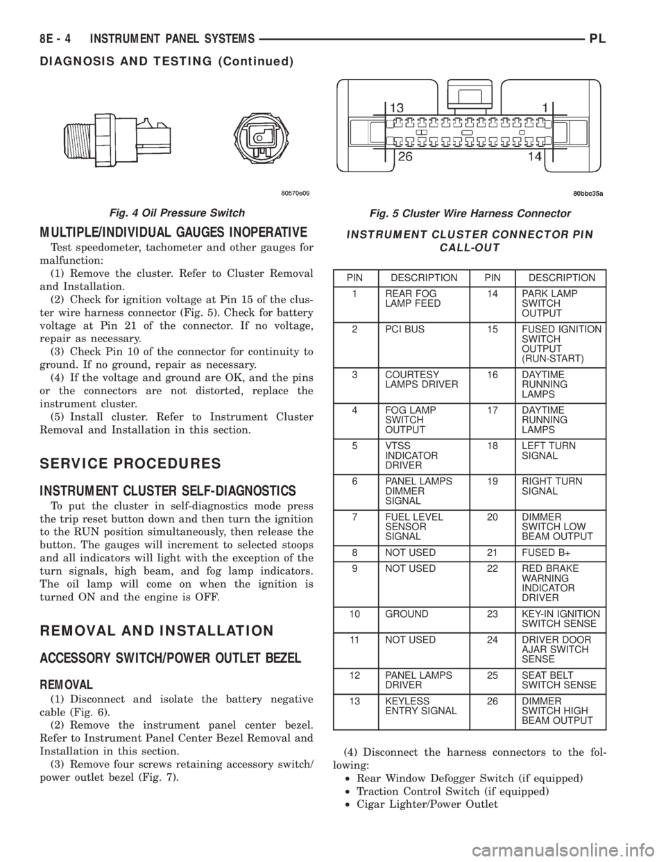
(2) Check for ignition voltage at Pin 15 of the clus-
ter wire harness connector (Fig. 5). Check for battery
voltage at Pin 21 of the connector. If no voltage,
repair as necessary.
(3) Check Pin 10 of the connector for continuity to
ground. If no ground, repair as necessary.
(4) If the voltage and ground are OK, and the pins
or the connectors are not distorted, replace the
instrument cluster.
(5) Install cluster. Refer to Instrument Cluster
Removal and Installation in this section.
SERVICE PROCEDURES
INSTRUMENT CLUSTER SELF-DIAGNOSTICS
To put the cluster in self-diagnostics mode press
the trip reset button down and then turn the ignition
to the RUN position simultaneously, then release the
button. The gauges will increment to selected stoops
and all indicators will light with the exception of the
turn signals, high beam, and fog lamp indicators.
The oil lamp will come on when the ignition is
turned ON and the engine is OFF.
REMOVAL AND INSTALLATION
ACCESSORY SWITCH/POWER OUTLET BEZEL
REMOVAL
(1) Disconnect and isolate the battery negative
cable (Fig. 6).
(2) Remove the instrument panel center bezel.
Refer to Instrument Panel Center Bezel Removal and
Installation in this section.
(3) Remove four screws retaining accessory switch/
power outlet bezel (Fig. 7).(4) Disconnect the harness connectors to the fol-
lowing:
²Rear Window Defogger Switch (if equipped)
²Traction Control Switch (if equipped)
²Cigar Lighter/Power Outlet
Fig. 5 Cluster Wire Harness Connector
INSTRUMENT CLUSTER CONNECTOR PIN
CALL-OUT
PIN DESCRIPTION PIN DESCRIPTION
1 REAR FOG
LAMP FEED14 PARK LAMP
SWITCH
OUTPUT
2 PCI BUS 15 FUSED IGNITION
SWITCH
OUTPUT
(RUN-START)
3 COURTESY
LAMPS DRIVER16 DAYTIME
RUNNING
LAMPS
4 FOG LAMP
SWITCH
OUTPUT17 DAYTIME
RUNNING
LAMPS
5 VTSS
INDICATOR
DRIVER18 LEFT TURN
SIGNAL
6 PANEL LAMPS
DIMMER
SIGNAL19 RIGHT TURN
SIGNAL
7 FUEL LEVEL
SENSOR
SIGNAL20 DIMMER
SWITCH LOW
BEAM OUTPUT
8 NOT USED 21 FUSED B+
9 NOT USED 22 RED BRAKE
WARNING
INDICATOR
DRIVER
10 GROUND 23 KEY-IN IGNITION
SWITCH SENSE
11 NOT USED 24 DRIVER DOOR
AJAR SWITCH
SENSE
12 PANEL LAMPS
DRIVER25 SEAT BELT
SWITCH SENSE
13 KEYLESS
ENTRY SIGNAL26 DIMMER
SWITCH HIGH
BEAM OUTPUT
Fig. 4 Oil Pressure Switch
8E - 4 INSTRUMENT PANEL SYSTEMSPL
DIAGNOSIS AND TESTING (Continued)
Page 252 of 1285
The accessory switches are not serviced separately,
but the cigar lighter/power outlet is and must be
transferred to the new bezel. Refer to Cigar Lighter/
Power Outlet Removal and Installation in this sec-
tion.
INSTALLATION
For installation reverse the above procedures.
CENTER CONSOLE FLOOD LAMP
REMOVAL
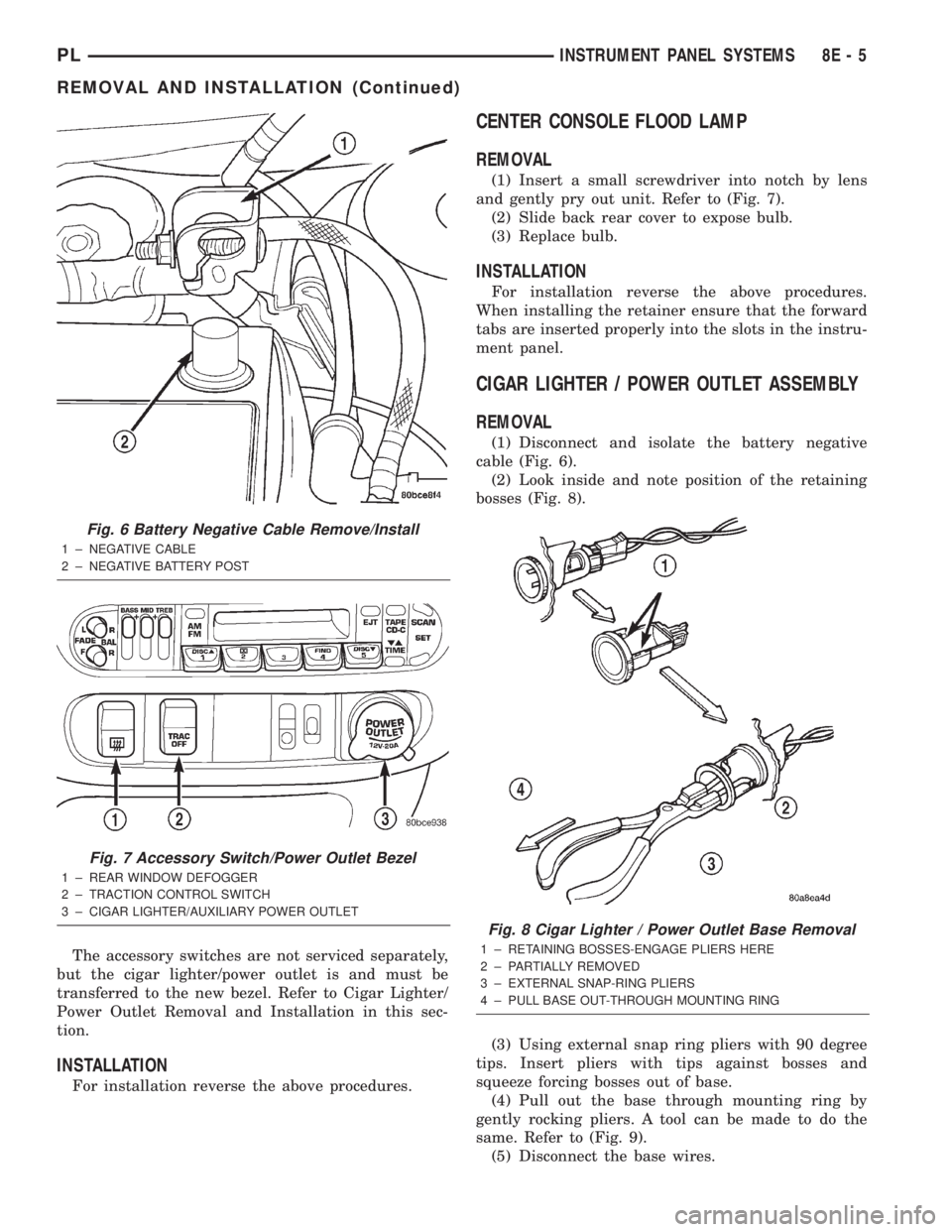
(1) Insert a small screwdriver into notch by lens
and gently pry out unit. Refer to (Fig. 7).
(2) Slide back rear cover to expose bulb.
(3) Replace bulb.
INSTALLATION
For installation reverse the above procedures.
When installing the retainer ensure that the forward
tabs are inserted properly into the slots in the instru-
ment panel.
CIGAR LIGHTER / POWER OUTLET ASSEMBLY
REMOVAL
(1) Disconnect and isolate the battery negative
cable (Fig. 6).
(2) Look inside and note position of the retaining
bosses (Fig. 8).
(3) Using external snap ring pliers with 90 degree
tips. Insert pliers with tips against bosses and
squeeze forcing bosses out of base.
(4) Pull out the base through mounting ring by
gently rocking pliers. A tool can be made to do the
same. Refer to (Fig. 9).
(5) Disconnect the base wires.
Fig. 6 Battery Negative Cable Remove/Install
1 ± NEGATIVE CABLE
2 ± NEGATIVE BATTERY POST
Fig. 7 Accessory Switch/Power Outlet Bezel
1 ± REAR WINDOW DEFOGGER
2 ± TRACTION CONTROL SWITCH
3 ± CIGAR LIGHTER/AUXILIARY POWER OUTLET
Fig. 8 Cigar Lighter / Power Outlet Base Removal
1 ± RETAINING BOSSES-ENGAGE PLIERS HERE
2 ± PARTIALLY REMOVED
3 ± EXTERNAL SNAP-RING PLIERS
4 ± PULL BASE OUT-THROUGH MOUNTING RING
PLINSTRUMENT PANEL SYSTEMS 8E - 5
REMOVAL AND INSTALLATION (Continued)
Page 356 of 1285
ELECTRICALLY HEATED SYSTEMS
TABLE OF CONTENTS
page page
DESCRIPTION AND OPERATION
REAR WINDOW DEFOGGER SYSTEM.........1
REAR WINDOW DEFOGGER SWITCH.........1
DIAGNOSIS AND TESTING
GRID LINES.............................2
REAR WINDOW DEFOGGER SWITCH.........2REAR WINDOW DEFOGGER SYSTEM.........2
SERVICE PROCEDURES
GRID LINE AND TERMINAL REPAIR..........3
REMOVAL AND INSTALLATION
REAR WINDOW DEFOGGER SWITCH.........4
DESCRIPTION AND OPERATION
REAR WINDOW DEFOGGER SYSTEM
For proper operation of the Rear Window Defogger
system refer to the Owner's Manual.
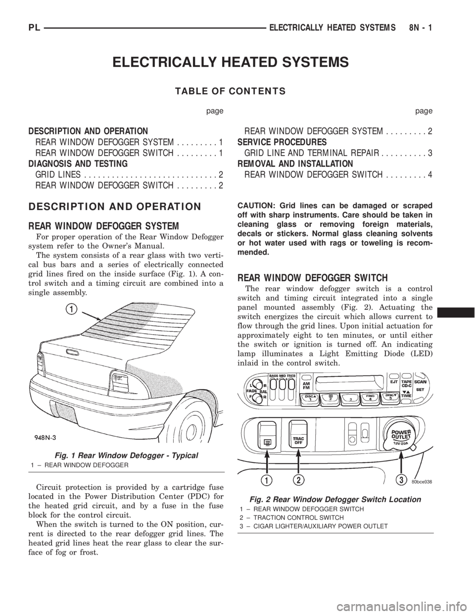
The system consists of a rear glass with two verti-
cal bus bars and a series of electrically connected
grid lines fired on the inside surface (Fig. 1). A con-
trol switch and a timing circuit are combined into a
single assembly.
Circuit protection is provided by a cartridge fuse
located in the Power Distribution Center (PDC) for
the heated grid circuit, and by a fuse in the fuse
block for the control circuit.
When the switch is turned to the ON position, cur-
rent is directed to the rear defogger grid lines. The
heated grid lines heat the rear glass to clear the sur-
face of fog or frost.CAUTION: Grid lines can be damaged or scraped
off with sharp instruments. Care should be taken in
cleaning glass or removing foreign materials,
decals or stickers. Normal glass cleaning solvents
or hot water used with rags or toweling is recom-
mended.
REAR WINDOW DEFOGGER SWITCH
The rear window defogger switch is a control
switch and timing circuit integrated into a single
panel mounted assembly (Fig. 2). Actuating the
switch energizes the circuit which allows current to
flow through the grid lines. Upon initial actuation for
approximately eight to ten minutes, or until either
the switch or ignition is turned off. An indicating
lamp illuminates a Light Emitting Diode (LED)
inlaid in the control switch.
Fig. 1 Rear Window Defogger - Typical
1 ± REAR WINDOW DEFOGGER
Fig. 2 Rear Window Defogger Switch Location
1 ± REAR WINDOW DEFOGGER SWITCH
2 ± TRACTION CONTROL SWITCH
3 ± CIGAR LIGHTER/AUXILIARY POWER OUTLET
PLELECTRICALLY HEATED SYSTEMS 8N - 1
Page 411 of 1285
Component Page
Sunroof Switch.......................8W-64
Sunroof Vent Switch...................8W-64
Tail/Stop Lamps......................8W-51
Tail/Stop/Turn Signal Lamps..........8W-51, 52
Throttle Position Sensor................8W-30
Torque Converter Clutch Solenoid.........8W-30
Traction Control Switch.................8W-35
Trunk Key Cylinder Switch..............8W-61
Turn Signal Lamps....................8W-52
Underhood Lamp......................8W-44Component Page
Vehicle Speed Control Servo.............8W-33
Vehicle Speed Control Switch............8W-33
Vehicle Speed Sensor...................8W-30
Visor/Vanity Lamps....................8W-44
Wheel Speed Sensors...................8W-35
Windshield Washer Pump...............8W-53
Wipe/Wash Switch.....................8W-53
Wiper Motor.........................8W-53
8W - 02 - 2 8W - 02 COMPONENT INDEXPL
Page 454 of 1285
8W-15 GROUND DISTRIBUTION
Component Page
A/C Compressor Clutch................8W-15-5
A/C Compressor Clutch Relay...........8W-15-5
A/C Heater Control..................8W-15-10
Airbag Control Module................8W-15-8
Battery............................8W-15-8
Brake Lamp Switch..................8W-15-4
Brake Warning Indicator Switch........8W-15-3
Center High Mounted Stop Lamp....8W-15-12, 13
Center Stack Lamp..................8W-15-11
Cigar Lighter/Power Outlet............8W-15-11
Clockspring.........................8W-15-8
Clutch Interlock Switch...............8W-15-3
Controller Anti-Lock Brake.............8W-15-5
Data Link Connector.................8W-15-4
Decklid Solenoid.................8W-15-12, 13
Diode No. 1.........................8W-15-5
Dome Lamp/Intrusion Sensor..........8W-15-13
Driver Cylinder Lock Switch...........8W-15-9
Driver Door Lock Switch..............8W-15-9
Driver Power Mirror.................8W-15-10
Driver Power Window Switch........8W-15-9, 10
Fuel Pump Module..................8W-15-16
Fuel Tank.........................8W-15-16
G101............................8W-15-2, 3
G102..............................8W-15-4
G103............................8W-15-5, 7
G104..............................8W-15-8
G105..............................8W-15-8
G201..............................8W-15-8
G202..............................8W-15-8
G203...........................8W-15-9, 10
G204.............................8W-15-11
G301..........................8W-15-12, 13
G302..........................8W-15-14, 15
G303.............................8W-15-16
G304..........................8W-15-12, 13
Glove Box Lamp/Switch..............8W-15-11
Headlamp Leveling Switch............8W-15-11
High Note Horn...................8W-15-5, 6
Hood Ajar Switch....................8W-15-7
Instrument Cluster..................8W-15-11
Left Back-Up Lamp...............8W-15-12, 13
Left City Lamp......................8W-15-2
Left Front Fog Lamp.................8W-15-6
Left Front Side Marker Lamp..........8W-15-2
Left Front Turn Signal Lamp...........8W-15-2
Left Headlamp......................8W-15-2
Left Headlamp Leveling Motor..........8W-15-2
Left License Lamp..................8W-15-15Component Page
Left Park/Turn Signal Lamp............8W-15-2
Left Rear Fog Lamp.................8W-15-15
Left Rear Turn Signal Lamp...........8W-15-13
Left Repeater Lamp..................8W-15-2
Left Tail/Stop Lamp.................8W-15-13
Left Tail/Stop/Turn Signal Lamp........8W-15-12
License Lamp......................8W-15-14
Low Note Horn......................8W-15-5
Map/Reading Lamps.................8W-15-11
Multi-Function Switch...............8W-15-11
Oxygen Sensor 1/2 Downstream.........8W-15-3
Passenger Cylinder Lock Switch.........8W-15-9
Passenger Door Lock Switch............8W-15-9
Passenger Power Mirror...............8W-15-9
Passenger Power Window Switch........8W-15-9
Power Mirror Switch.................8W-15-10
Power Steering Pressure Switch.........8W-15-4
Powertrain Control Module............8W-15-4
PRNDL Lamp......................8W-15-11
Radiator Fan Motor..................8W-15-5
Radio.............................8W-15-8
Rear Window Defogger............8W-15-12, 13
Rear Window Defogger Switch..........8W-15-8
Remote Keyless Entry Module........8W-15-8, 11
Right Back-Up Lamp..............8W-15-14, 15
Right City Lamp.....................8W-15-7
Right Front Fog Lamp................8W-15-6
Right Front Side Marker Lamp.........8W-15-7
Right Front Turn Signal Lamp..........8W-15-7
Right Headlamp.....................8W-15-7
Right Headlamp Leveling Motor.........8W-15-7
Right License Lamp.................8W-15-15
Right Park/Turn Signal Lamp..........8W-15-7
Right Rear Fog Lamp................8W-15-15
Right Rear Turn Signal Lamp..........8W-15-15
Right Repeater Lamp.................8W-15-7
Right Tail/Stop Lamp................8W-15-15
Right Tail/Stop/Turn Signal Lamp......8W-15-14
Seat Belt Switch.................8W-15-12, 13
Sentry Key Immobilizer Module.........8W-15-8
Siren..............................8W-15-7
Sunroof Control Module..............8W-15-11
Traction Control Switch..............8W-15-11
Trunk Key Cylinder Switch.........8W-15-12, 13
Underhood Lamp....................8W-15-3
Vehicle Speed Control Servo............8W-15-3
Windshield Washer Pump..............8W-15-5
Wipe/Wash Switch...................8W-15-8
Wiper Motor.......................8W-15-11
PL8W - 15 GROUND DISTRIBUTION 8W - 15 - 1
Page 464 of 1285

2
3
CB
2
2
10
7
12
31
3
MOTOR WIPER TRACTION
CONTROL
SWITCH
MULTI-
FUNCTION
SWITCH MODULE ENTRY
KEYLESS
REMOTE OUTLET POWER
LIGHTER/
CIGAR EXPORT) (BUILT-UP-
SWITCH
LEVELING
HEADLAMP LAMP PRNDL
SWITCH LAMP/
BOX
GLOVE
CENTER
STACK
LAMP
CLUSTER INSTRUMENTSUNROOF
CONTROL
MODULEMAP/
READING
LAMPS
POWER
SUNROOF OTHER
C2025
3C204
G204 S202S205 S252
Z3
20
BK/ORZ3
20
BK/ORZ3
20
BK/ORZ3
16
BK/OR
Z3
18
BK/ORZ3
18
BK/OR
Z3
18
BK/OR
Z3
18
BK/OR
Z3
14
BK/OR
Z1
16
BK
Z1
16
BKZ1
16
BKZ1
20
BKZ1
20
BKZ1
20
BKZ1
20
BK
Z1
16
BK
C3063
Z3
18
BK/OR
(8W-53-3) (8W-35-3)
(8W-52-3)
(8W-52-4) (8W-39-2) (8W-41-4) (8W-50-8) (8W-44-5)
(8W-44-4)
(8W-44-5)
(8W-40-2)(8W-64-2) (8W-44-3)
PL8W-15 GROUND DISTRIBUTION 8W - 15 - 11
PLI01511008W-10