2000 DODGE NEON reset
[x] Cancel search: resetPage 14 of 1285
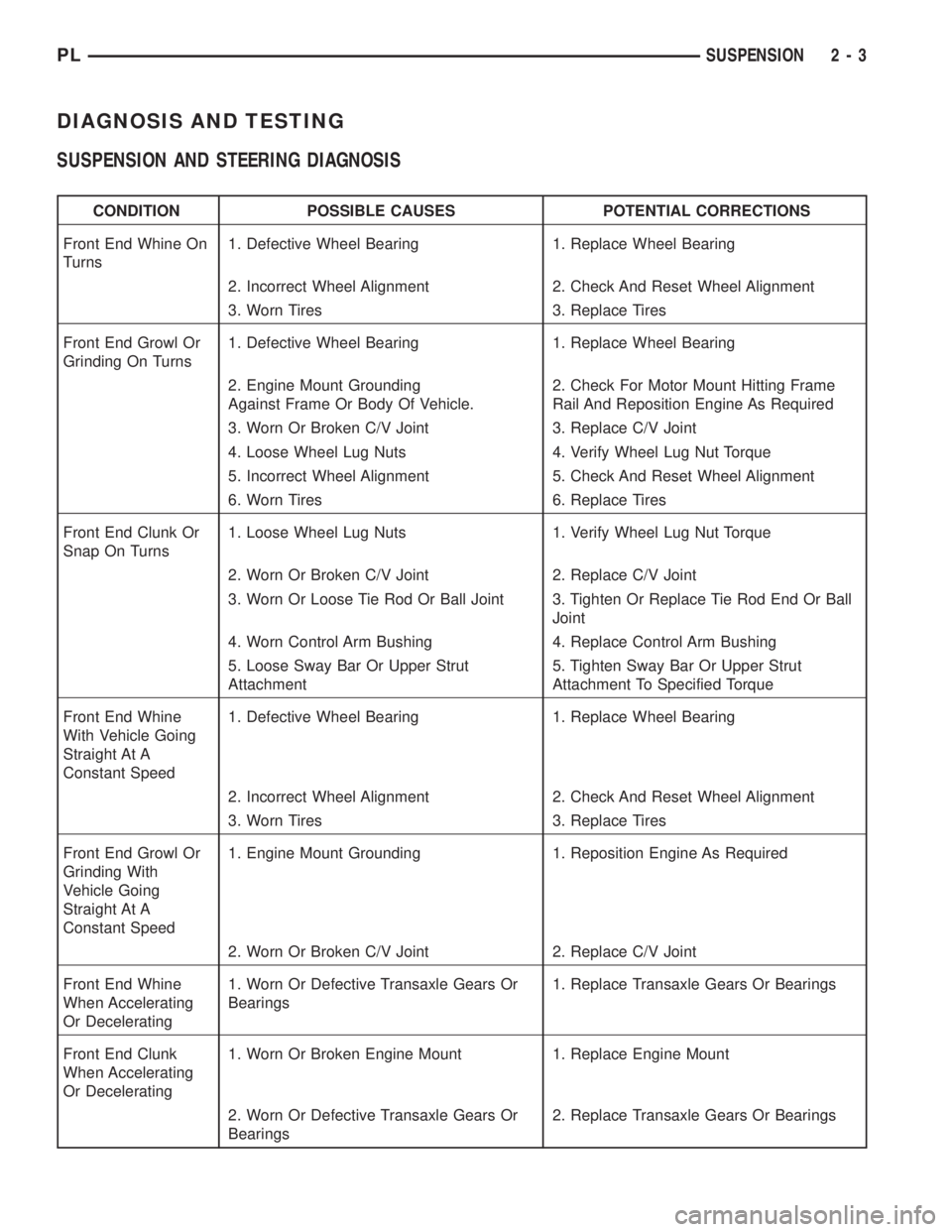
DIAGNOSIS AND TESTING
SUSPENSION AND STEERING DIAGNOSIS
CONDITION POSSIBLE CAUSES POTENTIAL CORRECTIONS
Front End Whine On
Turns1. Defective Wheel Bearing 1. Replace Wheel Bearing
2. Incorrect Wheel Alignment 2. Check And Reset Wheel Alignment
3. Worn Tires 3. Replace Tires
Front End Growl Or
Grinding On Turns1. Defective Wheel Bearing 1. Replace Wheel Bearing
2. Engine Mount Grounding
Against Frame Or Body Of Vehicle.2. Check For Motor Mount Hitting Frame
Rail And Reposition Engine As Required
3. Worn Or Broken C/V Joint 3. Replace C/V Joint
4. Loose Wheel Lug Nuts 4. Verify Wheel Lug Nut Torque
5. Incorrect Wheel Alignment 5. Check And Reset Wheel Alignment
6. Worn Tires 6. Replace Tires
Front End Clunk Or
Snap On Turns1. Loose Wheel Lug Nuts 1. Verify Wheel Lug Nut Torque
2. Worn Or Broken C/V Joint 2. Replace C/V Joint
3. Worn Or Loose Tie Rod Or Ball Joint 3. Tighten Or Replace Tie Rod End Or Ball
Joint
4. Worn Control Arm Bushing 4. Replace Control Arm Bushing
5. Loose Sway Bar Or Upper Strut
Attachment5. Tighten Sway Bar Or Upper Strut
Attachment To Specified Torque
Front End Whine
With Vehicle Going
Straight At A
Constant Speed1. Defective Wheel Bearing 1. Replace Wheel Bearing
2. Incorrect Wheel Alignment 2. Check And Reset Wheel Alignment
3. Worn Tires 3. Replace Tires
Front End Growl Or
Grinding With
Vehicle Going
Straight At A
Constant Speed1. Engine Mount Grounding 1. Reposition Engine As Required
2. Worn Or Broken C/V Joint 2. Replace C/V Joint
Front End Whine
When Accelerating
Or Decelerating1. Worn Or Defective Transaxle Gears Or
Bearings1. Replace Transaxle Gears Or Bearings
Front End Clunk
When Accelerating
Or Decelerating1. Worn Or Broken Engine Mount 1. Replace Engine Mount
2. Worn Or Defective Transaxle Gears Or
Bearings2. Replace Transaxle Gears Or Bearings
PLSUSPENSION 2 - 3
Page 15 of 1285
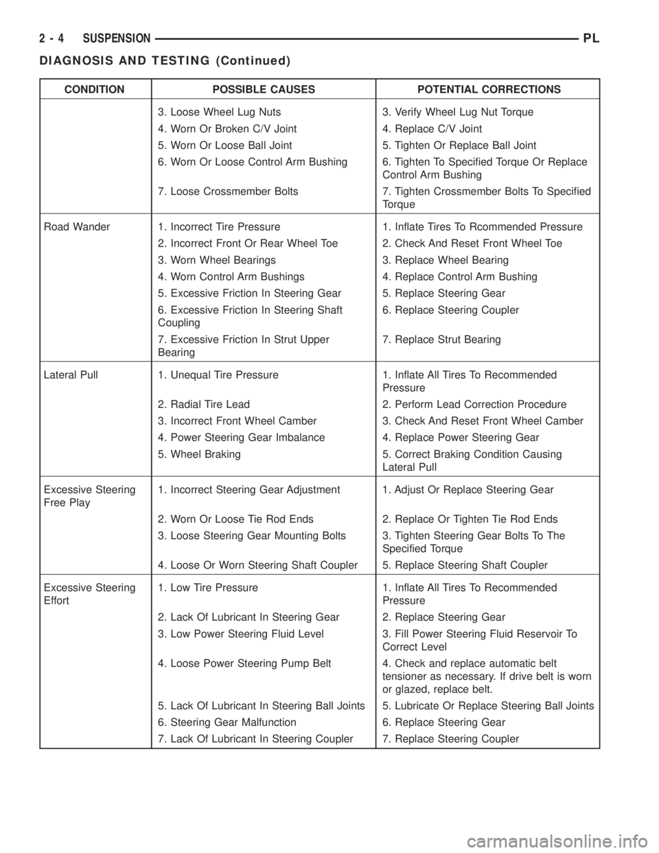
CONDITION POSSIBLE CAUSES POTENTIAL CORRECTIONS
3. Loose Wheel Lug Nuts 3. Verify Wheel Lug Nut Torque
4. Worn Or Broken C/V Joint 4. Replace C/V Joint
5. Worn Or Loose Ball Joint 5. Tighten Or Replace Ball Joint
6. Worn Or Loose Control Arm Bushing 6. Tighten To Specified Torque Or Replace
Control Arm Bushing
7. Loose Crossmember Bolts 7. Tighten Crossmember Bolts To Specified
Torque
Road Wander 1. Incorrect Tire Pressure 1. Inflate Tires To Rcommended Pressure
2. Incorrect Front Or Rear Wheel Toe 2. Check And Reset Front Wheel Toe
3. Worn Wheel Bearings 3. Replace Wheel Bearing
4. Worn Control Arm Bushings 4. Replace Control Arm Bushing
5. Excessive Friction In Steering Gear 5. Replace Steering Gear
6. Excessive Friction In Steering Shaft
Coupling6. Replace Steering Coupler
7. Excessive Friction In Strut Upper
Bearing7. Replace Strut Bearing
Lateral Pull 1. Unequal Tire Pressure 1. Inflate All Tires To Recommended
Pressure
2. Radial Tire Lead 2. Perform Lead Correction Procedure
3. Incorrect Front Wheel Camber 3. Check And Reset Front Wheel Camber
4. Power Steering Gear Imbalance 4. Replace Power Steering Gear
5. Wheel Braking 5. Correct Braking Condition Causing
Lateral Pull
Excessive Steering
Free Play1. Incorrect Steering Gear Adjustment 1. Adjust Or Replace Steering Gear
2. Worn Or Loose Tie Rod Ends 2. Replace Or Tighten Tie Rod Ends
3. Loose Steering Gear Mounting Bolts 3. Tighten Steering Gear Bolts To The
Specified Torque
4. Loose Or Worn Steering Shaft Coupler 5. Replace Steering Shaft Coupler
Excessive Steering
Effort1. Low Tire Pressure 1. Inflate All Tires To Recommended
Pressure
2. Lack Of Lubricant In Steering Gear 2. Replace Steering Gear
3. Low Power Steering Fluid Level 3. Fill Power Steering Fluid Reservoir To
Correct Level
4. Loose Power Steering Pump Belt 4. Check and replace automatic belt
tensioner as necessary. If drive belt is worn
or glazed, replace belt.
5. Lack Of Lubricant In Steering Ball Joints 5. Lubricate Or Replace Steering Ball Joints
6. Steering Gear Malfunction 6. Replace Steering Gear
7. Lack Of Lubricant In Steering Coupler 7. Replace Steering Coupler
2 - 4 SUSPENSIONPL
DIAGNOSIS AND TESTING (Continued)
Page 154 of 1285
ABS ELECTRONIC DIAGNOSIS
The following information is presented to give the
technician a general background on the diagnostic
capabilities of the ABS system. Complete electronic
diagnosis of the ABS system used on this vehicle is
covered in the Chassis Diagnostic Procedures manual.
Electronic diagnosis of the ABS system used on
this vehicle is performed using the DRBIIItscan
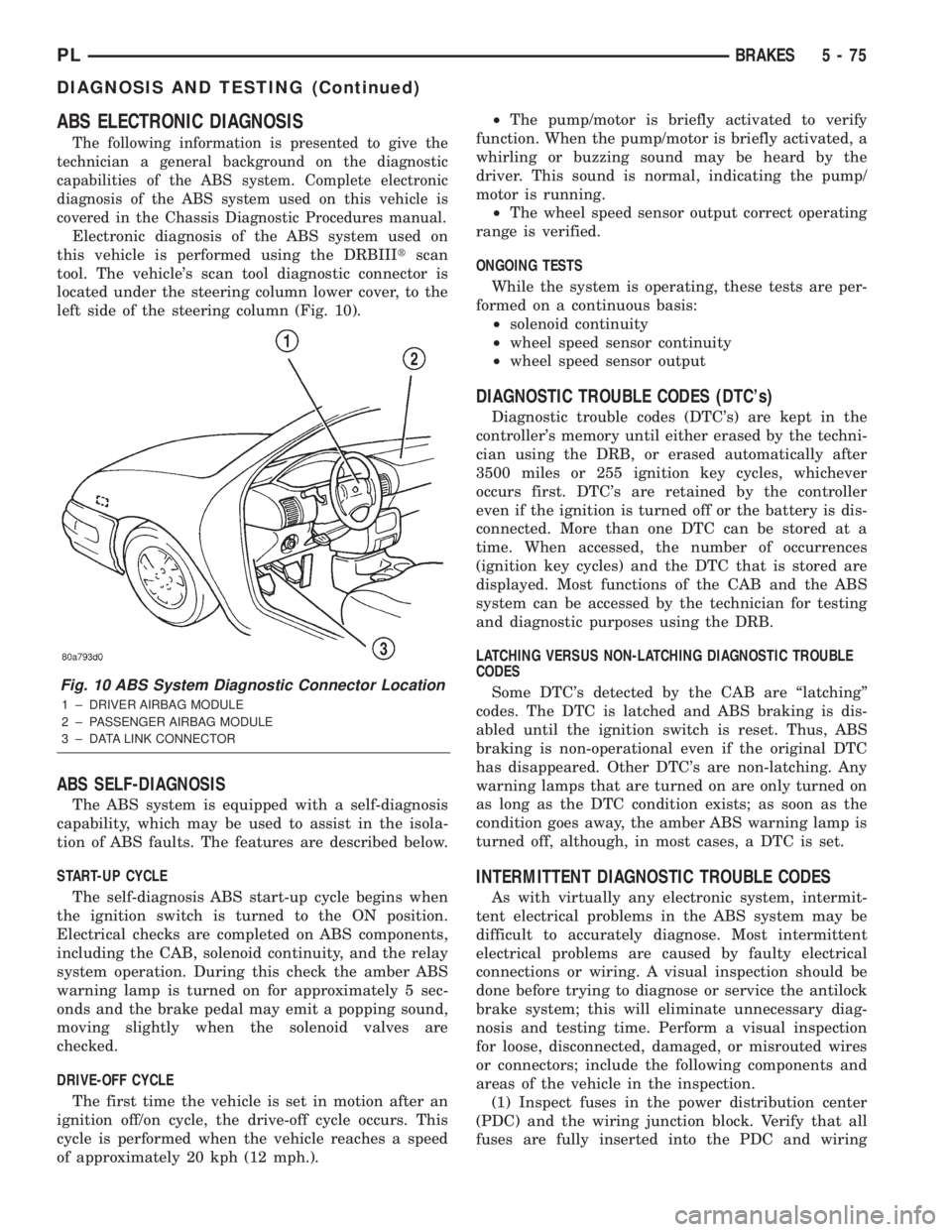
tool. The vehicle's scan tool diagnostic connector is
located under the steering column lower cover, to the
left side of the steering column (Fig. 10).
ABS SELF-DIAGNOSIS
The ABS system is equipped with a self-diagnosis
capability, which may be used to assist in the isola-
tion of ABS faults. The features are described below.
START-UP CYCLE
The self-diagnosis ABS start-up cycle begins when
the ignition switch is turned to the ON position.
Electrical checks are completed on ABS components,
including the CAB, solenoid continuity, and the relay
system operation. During this check the amber ABS
warning lamp is turned on for approximately 5 sec-
onds and the brake pedal may emit a popping sound,
moving slightly when the solenoid valves are
checked.
DRIVE-OFF CYCLE
The first time the vehicle is set in motion after an
ignition off/on cycle, the drive-off cycle occurs. This
cycle is performed when the vehicle reaches a speed
of approximately 20 kph (12 mph.).²The pump/motor is briefly activated to verify
function. When the pump/motor is briefly activated, a
whirling or buzzing sound may be heard by the
driver. This sound is normal, indicating the pump/
motor is running.
²The wheel speed sensor output correct operating
range is verified.
ONGOING TESTS
While the system is operating, these tests are per-
formed on a continuous basis:
²solenoid continuity
²wheel speed sensor continuity
²wheel speed sensor output
DIAGNOSTIC TROUBLE CODES (DTC's)
Diagnostic trouble codes (DTC's) are kept in the
controller's memory until either erased by the techni-
cian using the DRB, or erased automatically after
3500 miles or 255 ignition key cycles, whichever
occurs first. DTC's are retained by the controller
even if the ignition is turned off or the battery is dis-
connected. More than one DTC can be stored at a
time. When accessed, the number of occurrences
(ignition key cycles) and the DTC that is stored are
displayed. Most functions of the CAB and the ABS
system can be accessed by the technician for testing
and diagnostic purposes using the DRB.
LATCHING VERSUS NON-LATCHING DIAGNOSTIC TROUBLE
CODES
Some DTC's detected by the CAB are ªlatchingº
codes. The DTC is latched and ABS braking is dis-
abled until the ignition switch is reset. Thus, ABS
braking is non-operational even if the original DTC
has disappeared. Other DTC's are non-latching. Any
warning lamps that are turned on are only turned on
as long as the DTC condition exists; as soon as the
condition goes away, the amber ABS warning lamp is
turned off, although, in most cases, a DTC is set.
INTERMITTENT DIAGNOSTIC TROUBLE CODES
As with virtually any electronic system, intermit-
tent electrical problems in the ABS system may be
difficult to accurately diagnose. Most intermittent
electrical problems are caused by faulty electrical
connections or wiring. A visual inspection should be
done before trying to diagnose or service the antilock
brake system; this will eliminate unnecessary diag-
nosis and testing time. Perform a visual inspection
for loose, disconnected, damaged, or misrouted wires
or connectors; include the following components and
areas of the vehicle in the inspection.
(1) Inspect fuses in the power distribution center
(PDC) and the wiring junction block. Verify that all
fuses are fully inserted into the PDC and wiring
Fig. 10 ABS System Diagnostic Connector Location
1 ± DRIVER AIRBAG MODULE
2 ± PASSENGER AIRBAG MODULE
3 ± DATA LINK CONNECTOR
PLBRAKES 5 - 75
DIAGNOSIS AND TESTING (Continued)
Page 166 of 1285
CLUTCH
TABLE OF CONTENTS
page page
DESCRIPTION AND OPERATION
MODULAR CLUTCH ASSEMBLY..............1
CLUTCH CABLE..........................1
CLUTCH INTERLOCK/UPSTOP SWITCH........1
DIAGNOSIS AND TESTING
CLUTCH SYSTEM DIAGNOSIS...............2
DRIVE PLATE MISALIGNMENT..............5
CLUTCH CHATTER COMPLAINTS............5
CLASH±INTO±REVERSE COMPLAINTS........5
CLUTCH INTERLOCK/UPSTOP SWITCH........5REMOVAL AND INSTALLATION
CLUTCH CABLE..........................7
CLUTCH INTERLOCK/UPSTOP SWITCH........8
MODULAR CLUTCH ASSEMBLY..............8
RELEASE BEARING AND FORK.............12
CLEANING AND INSPECTION
CLUTCH CONTAMINATION.................12
CLEANING PRECAUTIONS.................13
SPECIFICATIONS
TORQUE...............................13
DESCRIPTION AND OPERATION
MODULAR CLUTCH ASSEMBLY
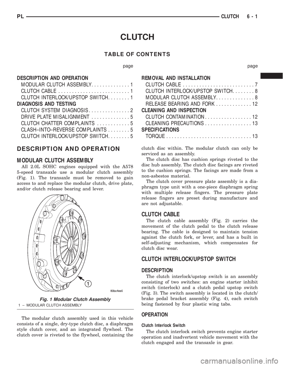
All 2.0L SOHC engines equipped with the A578
5-speed transaxle use a modular clutch assembly
(Fig. 1). The transaxle must be removed to gain
access to and replace the modular clutch, drive plate,
and/or clutch release bearing and lever.
The modular clutch assembly used in this vehicle
consists of a single, dry-type clutch disc, a diaphragm
style clutch cover, and an integrated flywheel. The
clutch cover is riveted to the flywheel, containing theclutch disc within. The modular clutch can only be
serviced as an assembly.
The clutch disc has cushion springs riveted to the
disc hub assembly. The clutch disc facings are riveted
to the cushion springs. The facings are made from a
non-asbestos material.
The clutch cover pressure plate assembly is a dia-
phragm type unit with a one-piece diaphragm spring
with multiple release fingers. The pressure plate
release fingers are preset during manufacture and
are not adjustable.
CLUTCH CABLE
The clutch cable assembly (Fig. 2) carries the
movement of the clutch pedal to the clutch release
bearing. The cable is designed to maintain tension
against the clutch fork, or lever, and has a built in
self-adjusting mechanism, which compensates for
clutch disc wear.
CLUTCH INTERLOCK/UPSTOP SWITCH
DESCRIPTION
The clutch interlock/upstop switch is an assembly
consisting of two switches: an engine starter inhibit
switch (interlock) and a clutch pedal upstop switch
(Fig. 3). The switch assembly is located in the clutch/
brake pedal bracket assembly (Fig. 4), each switch
being fastened by four plastic wing tabs.
OPERATION
Clutch Interlock Switch
The clutch interlock switch prevents engine starter
operation and inadvertent vehicle movement with the
clutch engaged and the transaxle in gear.
Fig. 1 Modular Clutch Assembly
1 ± MODULAR CLUTCH ASSEMBLY
PLCLUTCH 6 - 1
Page 249 of 1285
DESCRIPTION AND OPERATION
HEADLAMP SWITCH
The headlamp switch is part of the Multi-Function
Switch. Refer to Group 8J, Turn Signal and Flasher
for the Multi-Function Switch Test, Removal and
Installation procedures.
INSTRUMENT CLUSTER
There are two conventional instrument cluster
assemblies available. The clusters electronically drive
the speedometer, odometer, gauges, and tachometer
(if equipped). Refer to (Fig. 2) and (Fig. 3).
The instrument cluster controls the courtesy
lamps, it receives and sends messages to other mod-
ules via the PCI bus circuit, it controls all the instru-
ment illumination and the chime is also an integral
part of the cluster. The front turn signals are wired
through the cluster and then go to the front lamps.
The reason being that the DRL module is built into
the cluster (if equipped).
All gauges in the electronic clusters are the analog
type gauges. When the ignition switch is moved to
the OFF position, the cluster drives each gauge to its
lowest position. The individual gauges are not servi-
cable and require complete replacement of the cluster
if one or more gauges are inoperable.
One button is used to switch the display from trip
to total mileage. Holding the button when the display
is in the trip mode will reset the trip mileage. This
button is also used to put the cluster in self-diagnos-
tic mode. Refer to Service Procedures, Cluster Self-
Diagnostics in this section. Most of the indicators will
come on briefly for a bulb heck when the ignition is
turned from OFF to ON. All of the LED's are replace-
able.
In the event that the instrument cluster looses
communication with all other modules on the PCI
bus, the cluster will display ªnobusº in the VF dis-
play. The VF display also displays ªDoorº, ªCruiseº,
ªTracº, and odometer trip or total.
If the cluster does not detect voltage on the cour-
tesy lamp circuit, the message ªFUSEº will alternate
with the odometer/trip odometer for 30 seconds after
the ignition is turned on and for 15 seconds after the
vehicle is first moved. The lack of voltage can be due
to the M1 Fused B(+) (IOD) fuse being open, a bad or
missing courtesy lamp bulb, or a circuit problem.
WARNING AND INDICATOR LAMPS
The instrument cluster has warning lamps and
indicators for the following systems:
²Airbag
²Anti-lock Brakes (ABS) if equipped
²Brake warning
²Charging System²Front fog lamps (if equipped)
²High beam indicator
²Low fuel (premium cluster only)
²Low oil pressure
²Malfunction indicator (service engine soon) lamp
²Right and left turn signals
²Seat belt warning
²Security system
²Trac-Off (ABS equipped vehicles only)
The instrument cluster has a Vacuum Fluorescent
(VF) display for the following systems:
²Cruise
²Door (ajar)
²Odometer
²Set (cruise)
²Trac
²Trip
DIAGNOSIS AND TESTING
AIRBAG WARNING SYSTEM
For testing of this system refer to Group 8M, Pas-
sive Restraint Systems.
BRAKE SYSTEM WARNING LAMP TEST
The brake warning lamp illuminates when the
parking brake is applied with ignition switch turned
to the ON position. The same lamp will also illumi-
nate if one of the two service brake systems fail the
when brake pedal is applied.
To test the system:
²As the ignition switch is turned to the start posi-
tion the lamp should light.
²Turn ignition switch to the ON position and
apply the parking brake. The lamp should light.
If lamp fails to light inspect for:
²A burned out lamp
²Loose, corroded or damaged socket
²A damaged circuit board
²A broken or disconnected wire at the switch
²Defective switch
To test the service brake warning system, refer to
Group 5, Brakes, Hydraulic System Control Valves.
INSTRUMENT CLUSTER LAMPS
Every time the vehicle is switched to the START/
RUN position, the cluster goes through a BULB
CHECK. This tests most of the indicator lamps and
Vacuum Fluorescent (VF) displays. If only one lamp
is out, remove the instrument cluster and replace the
defective bulb or Light Emitting Diode (LED). If
some or all of the lamps fail to light, refer to the
proper Body Diagnostics Procedures Manual.
8E - 2 INSTRUMENT PANEL SYSTEMSPL
Page 250 of 1285
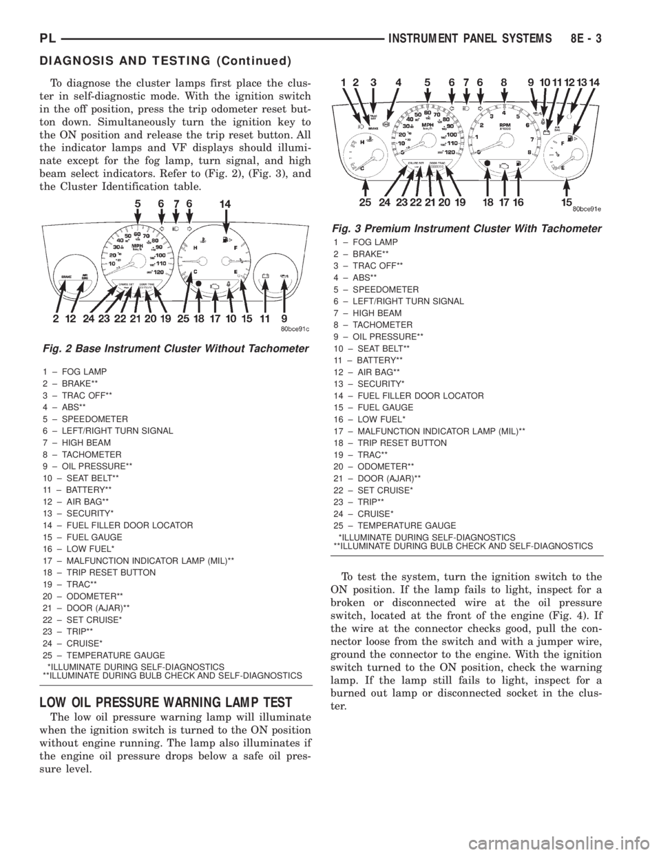
To diagnose the cluster lamps first place the clus-
ter in self-diagnostic mode. With the ignition switch
in the off position, press the trip odometer reset but-
ton down. Simultaneously turn the ignition key to
the ON position and release the trip reset button. All
the indicator lamps and VF displays should illumi-
nate except for the fog lamp, turn signal, and high
beam select indicators. Refer to (Fig. 2), (Fig. 3), and
the Cluster Identification table.
1 ± FOG LAMP
2 ± BRAKE**
3 ± TRAC OFF**
4 ± ABS**
5 ± SPEEDOMETER
6 ± LEFT/RIGHT TURN SIGNAL
7 ± HIGH BEAM
8 ± TACHOMETER
9 ± OIL PRESSURE**
10 ± SEAT BELT**
11 ± BATTERY**
12 ± AIR BAG**
13 ± SECURITY*
14 ± FUEL FILLER DOOR LOCATOR
15 ± FUEL GAUGE
16 ± LOW FUEL*
17 ± MALFUNCTION INDICATOR LAMP (MIL)**
18 ± TRIP RESET BUTTON
19 ± TRAC**
20 ± ODOMETER**
21 ± DOOR (AJAR)**
22 ± SET CRUISE*
23 ± TRIP**
24 ± CRUISE*
25 ± TEMPERATURE GAUGE
*ILLUMINATE DURING SELF-DIAGNOSTICS
**ILLUMINATE DURING BULB CHECK AND SELF-DIAGNOSTICS
LOW OIL PRESSURE WARNING LAMP TEST
The low oil pressure warning lamp will illuminate
when the ignition switch is turned to the ON position
without engine running. The lamp also illuminates if
the engine oil pressure drops below a safe oil pres-
sure level.To test the system, turn the ignition switch to the
ON position. If the lamp fails to light, inspect for a
broken or disconnected wire at the oil pressure
switch, located at the front of the engine (Fig. 4). If
the wire at the connector checks good, pull the con-
nector loose from the switch and with a jumper wire,
ground the connector to the engine. With the ignition
switch turned to the ON position, check the warning
lamp. If the lamp still fails to light, inspect for a
burned out lamp or disconnected socket in the clus-
ter.
Fig. 2 Base Instrument Cluster Without Tachometer
Fig. 3 Premium Instrument Cluster With Tachometer
1 ± FOG LAMP
2 ± BRAKE**
3 ± TRAC OFF**
4 ± ABS**
5 ± SPEEDOMETER
6 ± LEFT/RIGHT TURN SIGNAL
7 ± HIGH BEAM
8 ± TACHOMETER
9 ± OIL PRESSURE**
10 ± SEAT BELT**
11 ± BATTERY**
12 ± AIR BAG**
13 ± SECURITY*
14 ± FUEL FILLER DOOR LOCATOR
15 ± FUEL GAUGE
16 ± LOW FUEL*
17 ± MALFUNCTION INDICATOR LAMP (MIL)**
18 ± TRIP RESET BUTTON
19 ± TRAC**
20 ± ODOMETER**
21 ± DOOR (AJAR)**
22 ± SET CRUISE*
23 ± TRIP**
24 ± CRUISE*
25 ± TEMPERATURE GAUGE
*ILLUMINATE DURING SELF-DIAGNOSTICS
**ILLUMINATE DURING BULB CHECK AND SELF-DIAGNOSTICS
PLINSTRUMENT PANEL SYSTEMS 8E - 3
DIAGNOSIS AND TESTING (Continued)
Page 251 of 1285
MULTIPLE/INDIVIDUAL GAUGES INOPERATIVE
Test speedometer, tachometer and other gauges for
malfunction:
(1) Remove the cluster. Refer to Cluster Removal
and Installation.
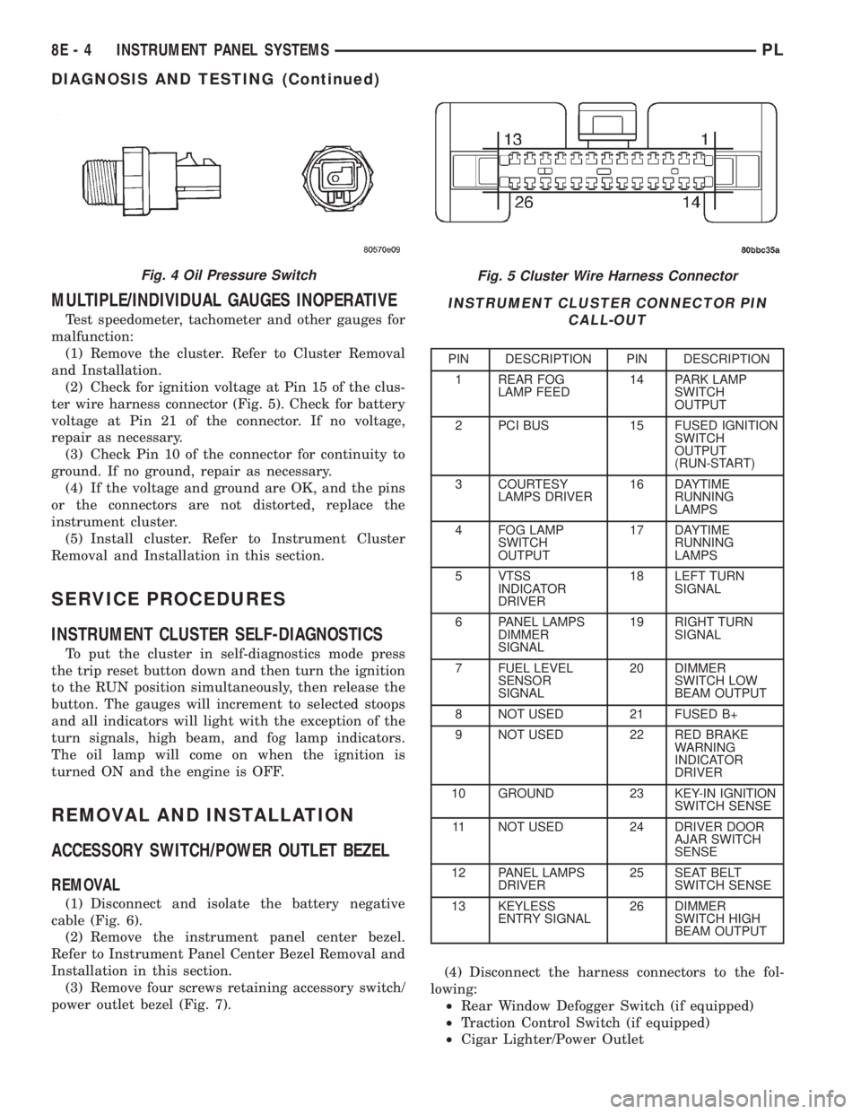
(2) Check for ignition voltage at Pin 15 of the clus-
ter wire harness connector (Fig. 5). Check for battery
voltage at Pin 21 of the connector. If no voltage,
repair as necessary.
(3) Check Pin 10 of the connector for continuity to
ground. If no ground, repair as necessary.
(4) If the voltage and ground are OK, and the pins
or the connectors are not distorted, replace the
instrument cluster.
(5) Install cluster. Refer to Instrument Cluster
Removal and Installation in this section.
SERVICE PROCEDURES
INSTRUMENT CLUSTER SELF-DIAGNOSTICS
To put the cluster in self-diagnostics mode press
the trip reset button down and then turn the ignition
to the RUN position simultaneously, then release the
button. The gauges will increment to selected stoops
and all indicators will light with the exception of the
turn signals, high beam, and fog lamp indicators.
The oil lamp will come on when the ignition is
turned ON and the engine is OFF.
REMOVAL AND INSTALLATION
ACCESSORY SWITCH/POWER OUTLET BEZEL
REMOVAL
(1) Disconnect and isolate the battery negative
cable (Fig. 6).
(2) Remove the instrument panel center bezel.
Refer to Instrument Panel Center Bezel Removal and
Installation in this section.
(3) Remove four screws retaining accessory switch/
power outlet bezel (Fig. 7).(4) Disconnect the harness connectors to the fol-
lowing:
²Rear Window Defogger Switch (if equipped)
²Traction Control Switch (if equipped)
²Cigar Lighter/Power Outlet
Fig. 5 Cluster Wire Harness Connector
INSTRUMENT CLUSTER CONNECTOR PIN
CALL-OUT
PIN DESCRIPTION PIN DESCRIPTION
1 REAR FOG
LAMP FEED14 PARK LAMP
SWITCH
OUTPUT
2 PCI BUS 15 FUSED IGNITION
SWITCH
OUTPUT
(RUN-START)
3 COURTESY
LAMPS DRIVER16 DAYTIME
RUNNING
LAMPS
4 FOG LAMP
SWITCH
OUTPUT17 DAYTIME
RUNNING
LAMPS
5 VTSS
INDICATOR
DRIVER18 LEFT TURN
SIGNAL
6 PANEL LAMPS
DIMMER
SIGNAL19 RIGHT TURN
SIGNAL
7 FUEL LEVEL
SENSOR
SIGNAL20 DIMMER
SWITCH LOW
BEAM OUTPUT
8 NOT USED 21 FUSED B+
9 NOT USED 22 RED BRAKE
WARNING
INDICATOR
DRIVER
10 GROUND 23 KEY-IN IGNITION
SWITCH SENSE
11 NOT USED 24 DRIVER DOOR
AJAR SWITCH
SENSE
12 PANEL LAMPS
DRIVER25 SEAT BELT
SWITCH SENSE
13 KEYLESS
ENTRY SIGNAL26 DIMMER
SWITCH HIGH
BEAM OUTPUT
Fig. 4 Oil Pressure Switch
8E - 4 INSTRUMENT PANEL SYSTEMSPL
DIAGNOSIS AND TESTING (Continued)
Page 270 of 1285
AUDIO SYSTEM
TABLE OF CONTENTS
page page
GENERAL INFORMATION
INTRODUCTION..........................1
DESCRIPTION AND OPERATION
INTERFERENCE ELIMINATION...............1
DIAGNOSIS AND TESTING
AUDIO DIAGNOSTIC TEST PROCEDURES......1
TESTING................................1
BENCH TEST FOR ANTENNA MALFUNCTION...7REMOVAL AND INSTALLATION
CD CHANGER............................7
FRONT DOOR SPEAKER....................8
INSTRUMENT PANEL SPEAKER(S)...........8
MAST and ANTENNA ASSEMBLY.............8
RADIO..................................9
REAR SHELF SPEAKER(S).................10
GENERAL INFORMATION
INTRODUCTION
Operating instructions for the factory installed
audio systems can be found in the Owner's Manual
provided with the vehicle.
The vehicles are equipped with an Interior (Igni-
tion Off Draw) fuse in the Power Distribution Center
located in the engine compartment. After the Interior
(IOD) fuse or battery has been disconnected the clock
will require resetting. The radio station presets have
a nonvolatile memory and will retain the preset sta-
tions after a battery disconnect.
The available radio options are:
²AM/FM Stereo Cassette w/Clock
²AM/FM/CD
²AM/FM Cassette w/CD Changer Controls and
Display
²CD/4 Disc Changer - In-Dash (used w/Radio CD
Changer Controls)
DESCRIPTION AND OPERATION
INTERFERENCE ELIMINATION
The radio utilizes a ground wire plugged on to a
blade terminal and is bolted to the radio chassis.
Both connector and terminal should be securely
attached. The engine has two separate ground straps
to suppress ignition noise which may interfere with
radio reception.
²Left engine mount clip on strap
²Engine to shock tower reinforcement
Inductive type spark plug cables in the high ten-
sion circuit of the ignition system complete the inter-
ference suppression. Faulty or deteriorated spark
plug wires should be replaced.
DIAGNOSIS AND TESTING
AUDIO DIAGNOSTIC TEST PROCEDURES
CAUTION: The CD player will only operate between
approximate temperatures of -23ÉC and +65ÉC (-10ÉF
and +145ÉF).
Whenever a radio malfunction occurs;
(1) First check FUSES:
(a) Power Distribution Center (PDC), Interior
lamp fuse, M1 - Radio Memory Feed
(b) Fuse Block:
(I) Fuse 12, Illumination in the fuse block
(II) Fuse 16, Ignition feed in the fuse block
NOTE: The vehicles are shipped with the INTERIOR
LAMP fuse disconnected.
(2) Verify, the radio wire harness are properly con-
nected before starting normal diagnosis and repair
procedures. Refer to Audio Diagnostic Charts and/or
Group 8W, Wiring Diagrams, Radio Section.
TESTING
The antenna has a short cable which connects into
the instrument panel harness. The connection is
made on the right side of the instrument panel.
Antenna performance may be tested by substitut-
ing a known good antenna. It is also possible to
check short or open circuits with an ohmmeter or
continuity light once the antenna cable is discon-
nected from the radio as follows:
(1) Continuity should be present between the
antenna mast and radio end pin of antenna cable
plug (Fig. 1).
(2) No continuity should be observed or a very
high resistance of several megohms between the
ground shell of the connector and radio end pin.
PLAUDIO SYSTEM 8F - 1