2000 DODGE NEON reset
[x] Cancel search: resetPage 360 of 1285
POWER DISTRIBUTION SYSTEMS
TABLE OF CONTENTS
page page
DESCRIPTION AND OPERATION
POWER DISTRIBUTION SYSTEM.............1
POWER DISTRIBUTION CENTER (PDC).......1
FUSE BLOCK.............................2REMOVAL AND INSTALLATION
FUSE BLOCK.............................2
POWER DISTRIBUTION CENTER (PDC).......2
DESCRIPTION AND OPERATION
POWER DISTRIBUTION SYSTEM
This group covers the various standard and
optional power distribution components used on this
model. Refer to the Component Index of Group 8W -
Wiring Diagrams for complete circuit diagrams of the
various power distribution components.
The power distribution system for this vehicle is
designed to provide safe, reliable, centralized and
convenient to access distribution of the electrical cur-
rent required to operate all of the many standard
and optional factory-installed electrical and electronic
powertrain, chassis, safety, comfort and convenience
systems. At the same time, these systems were
designed to provide centralized locations for conduct-
ing diagnosis of faulty circuits, and for sourcing the
additional current requirements of many aftermarket
vehicle accessory and convenience items.
These power distribution systems also incorporate
various types of circuit control and protection fea-
tures, including:
²Fuses
²Fuse cartridges
²Fusible links
²Automatic resetting circuit breakers
²Relays
²Flashers
²Timers
²Circuit splice blocks.
The power distribution system for this vehicle con-
sists of the following components:
²Power Distribution Center (PDC)
²Fuse Block
Following are general descriptions of the major
components in the power distribution system. Refer
to the owner's manual in the vehicle glove box for
more information on the features, use and operation
of all of the power distribution system components.
POWER DISTRIBUTION CENTER (PDC)
All of the electrical current distributed throughout
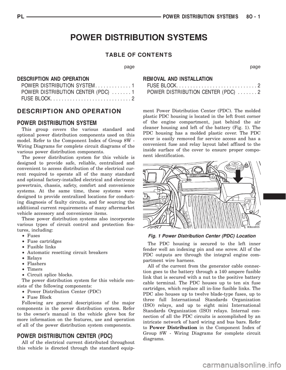
this vehicle is directed through the standard equip-ment Power Distribution Center (PDC). The molded
plastic PDC housing is located in the left front corner
of the engine compartment, just behind the air
cleaner housing and left of the battery (Fig. 1). The
PDC housing has a molded plastic cover. The PDC
cover is easily removed for service access and has a
convenient fuse and relay layout label affixed to the
inside surface of the cover to ensure proper compo-
nent identification.
The PDC housing is secured to the left inner
fender well an indexing pin and one screw. All of the
PDC outputs are through the integral engine com-
partment wire harness.
All of the current from the generator cable connec-
tion goes to the battery through a 140 ampere fusible
link that is secured with a nut to the positive battery
cable terminal. The PDC houses up to ten six fuse
cartridges, which replace all in-line fusible links. The
PDC also houses up to twelve blade-type fuses, up to
three full International Standards Organization
(ISO) relays, and up to eight mini International
Standards Organization (ISO) relays. Internal con-
nection of all the PDC circuits is accomplished by an
intricate network of hard wiring and bus bars. Refer
toPower Distributionin the Component Index of
Group 8W - Wiring Diagrams for complete circuit
diagrams.
Fig. 1 Power Distribution Center (PDC) Location
PLPOWER DISTRIBUTION SYSTEMS 8O - 1
Page 361 of 1285
The fusible link, fuses and relays are available for
service replacement. The PDC unit cannot be
repaired and is only serviced as a unit with the
engine compartment wire harness. If the PDC is
faulty or damaged, the engine compartment wire har-
ness assembly must be replaced.
FUSE BLOCK
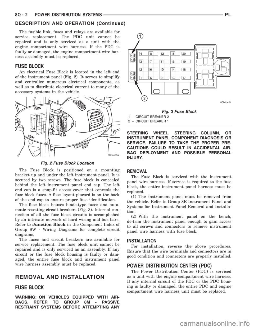
An electrical Fuse Block is located in the left end
of the instrument panel (Fig. 2). It serves to simplify
and centralize numerous electrical components, as
well as to distribute electrical current to many of the
accessory systems in the vehicle.
The Fuse Block is positioned on a mounting
bracket up and under the left instrument panel. It is
secured by two screws. The fuse block is concealed
behind the left instrument panel end cap. The left
end cap is a snap-fit access cover that conceals the
fuse block fuses. A fuse layout placard is on the back
of the end cap to ensure proper fuse identification.
The fuse block houses blade-type fuses and auto-
matic resetting circuit breakers (Fig. 3). Internal con-
nection of all the fuse block circuits is accomplished
by an intricate network of hard wiring and bus bars.
Refer toJunction Blockin the Component Index of
Group 8W - Wiring Diagrams for complete circuit
diagrams.
The fuses and circuit breakers are available for
service replacement. The fuse block unit cannot be
repaired and is only serviced as an assembly. If any
circuit or the fuse block housing is faulty or dam-
aged, the entire fuse block and instrument panel
wire harness assembly must be replaced.
REMOVAL AND INSTALLATION
FUSE BLOCK
WARNING: ON VEHICLES EQUIPPED WITH AIR-
BAGS, REFER TO GROUP 8M - PASSIVE
RESTRAINT SYSTEMS BEFORE ATTEMPTING ANYSTEERING WHEEL, STEERING COLUMN, OR
INSTRUMENT PANEL COMPONENT DIAGNOSIS OR
SERVICE. FAILURE TO TAKE THE PROPER PRE-
CAUTIONS COULD RESULT IN ACCIDENTAL AIR-
BAG DEPLOYMENT AND POSSIBLE PERSONAL
INJURY.
REMOVAL
The Fuse Block is serviced with the instrument
panel wire harness. If service is required to the fuse
block, the entire instrument panel harness must be
replaced.
(1) The instrument panel must be removed from
the vehicle. Refer to Group 8E-Instrument Panel and
Systems for Instrument Panel Removal and Installa-
tion.
(2) With the instrument panel on the bench,
de-trim the instrument panel enough to gain access
to all screws and connectors to remove instrument
panel wire harness with fuse block.
INSTALLATION
For installation, reverse the above procedures.
Ensure that the wire terminals and connectors are in
good condition and connectors are properly installed.
POWER DISTRIBUTION CENTER (PDC)
The Power Distribution Center (PDC) is serviced
as a unit with the engine compartment wire harness.
If any internal circuit of the PDC or the PDC hous-
ing is faulty or damaged, the entire PDC and engine
compartment wire harness unit must be replaced.
Fig. 2 Fuse Block Location
Fig. 3 Fuse Block
1 ± CIRCUIT BREAKER 2
2 ± CIRCUIT BREAKER 1
8O - 2 POWER DISTRIBUTION SYSTEMSPL
DESCRIPTION AND OPERATION (Continued)
Page 406 of 1285
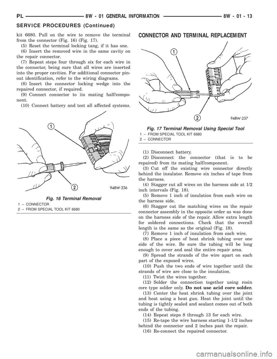
kit 6680. Pull on the wire to remove the terminal
from the connector (Fig. 16) (Fig. 17).
(5) Reset the terminal locking tang, if it has one.
(6) Insert the removed wire in the same cavity on
the repair connector.
(7) Repeat steps four through six for each wire in
the connector, being sure that all wires are inserted
into the proper cavities. For additional connector pin-
out identification, refer to the wiring diagrams.
(8) Insert the connector locking wedge into the
repaired connector, if required.
(9) Connect connector to its mating half/compo-
nent.
(10) Connect battery and test all affected systems.CONNECTOR AND TERMINAL REPLACEMENT
(1) Disconnect battery.
(2) Disconnect the connector (that is to be
repaired) from its mating half/component.
(3) Cut off the existing wire connector directly
behind the insulator. Remove six inches of tape from
the harness.
(4) Stagger cut all wires on the harness side at 1/2
inch intervals (Fig. 18).
(5) Remove 1 inch of insulation from each wire on
the harness side.
(6) Stagger cut the matching wires on the repair
connector assembly in the opposite order as was done
on the harness side of the repair. Allow extra length
for soldered connections. Check that the overall
length is the same as the original (Fig. 18).
(7) Remove 1 inch of insulation from each wire.
(8) Place a piece of heat shrink tubing over one
side of the wire. Be sure the tubing will be long
enough to cover and seal the entire repair area.
(9) Spread the strands of the wire apart on each
part of the exposed wires.
(10) Push the two ends of wire together until the
strands of wire are close to the insulation.
(11) Twist the wires together.
(12) Solder the connection together using rosin
core type solder only.Do not use acid core solder.
(13) Center the heat shrink tubing over the joint
and heat using a heat gun. Heat the joint until the
tubing is tightly sealed and sealant comes out of both
ends of the tubing.
(14) Repeat steps 8 through 13 for each wire.
(15) Re-tape the wire harness starting 1-1/2 inches
behind the connector and 2 inches past the repair.
(16) Re-connect the repaired connector.
Fig. 16 Terminal Removal
1 ± CONNECTOR
2 ± FROM SPECIAL TOOL KIT 6680
Fig. 17 Terminal Removal Using Special Tool
1 ± FROM SPECIAL TOOL KIT 6680
2 ± CONNECTOR
PL8W - 01 GENERAL INFORMATION 8W - 01 - 13
SERVICE PROCEDURES (Continued)
Page 811 of 1285
CAUTION: After removing the steering knuckle from
the ball joint stud, do not pull outward on the knuckle.
Pulling the steering knuckle outward at this point can
separate the inner C/V joint on the driveshaft. Refer to
FRONT DRIVESHAFTS in the DIFFERENTIAL AND
DRIVELINE group for further information.
NOTE: Use caution when separating the ball joint
stud from the steering knuckle, so the ball joint seal
does not get cut.
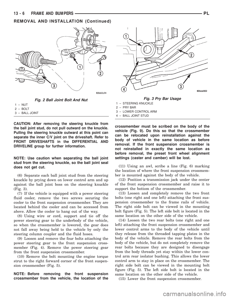
(6) Separate each ball joint stud from the steering
knuckle by prying down on lower control arm and up
against the ball joint boss on the steering knuckle
(Fig. 3).
(7) If the vehicle is equipped with a power steering
fluid cooler, remove the two screws securing the
cooler to the front suspension crossmember. They are
located behind the cooler and can be accessed from
above. Allow the cooler to hang out of the way.
(8) Using wire or cord, support and tie off the
power steering gear to the underbody of the vehicle,
so when the crossmember is lowered, the gear does
not fall away being held to the vehicle by only the
steering column coupler and the fluid hoses.
(9) Loosen and remove the four bolts attaching the
power steering gear to the front suspension cross-
member (Fig. 4). Remove the power steering gear
from the front suspension crossmember.
(10) Remove the bolt mounting the engine torque
strut to the right forward corner of the front suspen-
sion crossmember (Fig. 5).
NOTE: Before removing the front suspension
crossmember from the vehicle, the location of thecrossmember must be scribed on the body of the
vehicle (Fig. 9). Do this so that the crossmember
can be relocated upon reinstallation against the
body of vehicle in the same location as before
removal. If the front suspension crossmember is
not reinstalled in exactly the same location as
before removal, the preset front wheel alignment
settings (caster and camber) will be lost.
(11) Using an awl, scribe a line (Fig. 6) marking
the location of where the front suspension crossmem-
ber is mounted against the body of the vehicle.
(12) Position a transmission jack under the center
of the front suspension crossmember and raise it to
support the bottom of the crossmember.
(13) Loosen and completely remove the two front
bolts (one right and one left) attaching the front sus-
pension crossmember to the frame rails of vehicle.
The right side bolt can be viewed in the mounting
bolt figure (Fig. 5). The left side bolt is located in the
same location on the other side of the vehicle.
(14) Loosen the two rear bolts (one right and one
left) attaching the front suspension crossmember and
lower control arms to the body of the vehicle until
they release from the threaded tapping plates in the
body of the vehicle. Remove the rear bolts from the
body of the vehicle, but do not completely remove the
rear bolts because they are designed to disengage
from the body threads yet stay within the lower con-
trol arm rear isolator bushing. This allows the lower
control arm to stay in place on the crossmember. The
right side bolt can be viewed in the mounting bolt
figure (Fig. 5). The left side bolt is located in the
same location on the other side of the vehicle.
(15) Lower the front suspension crossmember.
Fig. 2 Ball Joint Bolt And Nut
1 ± NUT
2 ± BOLT
3 ± BALL JOINT
Fig. 3 Pry Bar Usage
1 ± STEERING KNUCKLE
2±PRYBAR
3 ± LOWER CONTROL ARM
4 ± BALL JOINT STUD
13 - 6 FRAME AND BUMPERSPL
REMOVAL AND INSTALLATION (Continued)
Page 843 of 1285
DESCRIPTION AND OPERATION
INJECTION SYSTEM
All engines used in this section have a sequential
Multi-Port Electronic Fuel Injection system. The MPI
system is computer regulated and provides precise
air/fuel ratios for all driving conditions. The Power-
train Control Module (PCM) operates the fuel injec-
tion system.
The PCM regulates:
²Ignition timing
²Air/fuel ratio
²Emission control devices
²Cooling fan
²Charging system
²Idle speed
²Vehicle speed control
Various sensors provide the inputs necessary for
the PCM to correctly operate these systems. In addi-
tion to the sensors, various switches also provide
inputs to the PCM.
All inputs to the PCM are converted into signals.
The PCM can adapt its programming to meet chang-
ing operating conditions.
Fuel is injected into the intake port above the
intake valve in precise metered amounts through
electrically operated injectors. The PCM fires the
injectors in a specific sequence. Under most operat-
ing conditions, the PCM maintains an air fuel ratio
of 14.7 parts air to 1 part fuel by constantly adjust-
ing injector pulse width. Injector pulse width is the
length of time the injector is open.
The PCM adjusts injector pulse width by opening
and closing the ground path to the injector. Engine
RPM (speed) and manifold absolute pressure (air
density) are the primary inputs that determine injec-
tor pulse width.
MODES OF OPERATION
OPERATION
As input signals to the PCM change, the PCM
adjusts its response to output devices. For example,
the PCM must calculate a different injector pulse
width and ignition timing for idle than it does for
Wide Open Throttle (WOT). There are several differ-
ent modes of operation that determine how the PCM
responds to the various input signals.
There are two different areas of operation, OPEN
LOOP and CLOSED LOOP.
During OPEN LOOP modes the PCM receives
input signals and responds according to preset PCM
programming. Inputs from the upstream and down-
stream heated oxygen sensors are not monitored dur-
ing OPEN LOOP modes, except for heated oxygensensor diagnostics (they are checked for shorted con-
ditions at all times).
During CLOSED LOOP modes the PCM monitors
the inputs from the upstream and downstream
heated oxygen sensors. The upstream heated oxygen
sensor input tells the PCM if the calculated injector
pulse width resulted in the ideal air-fuel ratio of 14.7
to one. By monitoring the exhaust oxygen content
through the upstream heated oxygen sensor, the
PCM can fine tune injector pulse width. Fine tuning
injector pulse width allows the PCM to achieve opti-
mum fuel economy combined with low emissions.
For the PCM to enter CLOSED LOOP operation,
the following must occur:
(1) Engine coolant temperature must be over 35ÉF.
²If the coolant is over 35É the PCM will wait 44
seconds.
²If the coolant is over 50ÉF the PCM will wait 38
seconds.
²If the coolant is over 167ÉF the PCM will wait
11 seconds.
(2) For other temperatures the PCM will interpo-
late the correct waiting time.
(3) O2 sensor must read either greater than 0.745
volts or less than 0.1 volt.
(4) The multi-port fuel injection systems has the
following modes of operation:
²Ignition switch ON (Zero RPM)
²Engine start-up
²Engine warm-up
²Cruise
²Idle
²Acceleration
²Deceleration
²Wide Open Throttle
²Ignition switch OFF
(5) The engine start-up (crank), engine warm-up,
deceleration with fuel shutoff and wide open throttle
modes are OPEN LOOP modes. Under most operat-
ing conditions, the acceleration, deceleration (with
A/C on), idle and cruise modes,with the engine at
operating temperatureare CLOSED LOOP modes.
IGNITION SWITCH ON (ZERO RPM) MODE
When the ignition switch activates the fuel injec-
tion system, the following actions occur:
²The PCM monitors the engine coolant tempera-
ture sensor and throttle position sensor input. The
PCM determines basic fuel injector pulse width from
this input.
²The PCM determines atmospheric air pressure
from the MAP sensor input to modify injector pulse
width.
When the key is in the ON position and the engine
is not running (zero rpm), the Auto Shutdown (ASD)
and fuel pump relays de-energize after approximately
14 - 22 FUEL SYSTEMPL
Page 847 of 1285
²Coolant temperature
²Engine speed (crankshaft position sensor)
²Engine run time
²Manifold absolute pressure
²Power steering pressure switch
²Throttle position
²Transmission gear selection (park/neutral
switch)
²Vehicle distance (speed)
The Auto Shutdown (ASD) and fuel pump relays
are mounted externally, but turned on and off by the
PCM.
The crankshaft position sensor signal is sent to the
PCM. If the PCM does not receive the signal within
approximately one second of engine cranking, it deac-
tivates the ASD relay and fuel pump relay. When
these relays deactivate, power is shut off from the
fuel injectors, ignition coils, heating element in the
oxygen sensors and the fuel pump.
The PCM contains a voltage converter that
changes battery voltage to a regulated 8 volts direct
current to power the camshaft position sensor, crank-
shaft position sensor and vehicle speed sensor. The
PCM also provides a 5 volt direct current supply for
the manifold absolute pressure sensor and throttle
position sensor.
PCM GROUND
OPERATION
Ground is provided through multiple pins of the
PCM connector. Depending on the vehicle there may
be as many as three different ground pins. There are
power grounds and sensor grounds.
The power grounds are used to control the ground
side of any relay, solenoid, ignition coil or injector.
The signal ground is used for any input that uses
sensor return for ground, and the ground side of any
internal processing component.
The SBEC III case is shielded to prevent RFI and
EMI. The PCM case is grounded and must be firmly
attached to a good, clean body ground.
Internally all grounds are connected together, how-
ever there is noise suppression on the sensor ground.
For EMI and RFI protection the case is also
grounded separately from the ground pins.
5 VOLT SUPPLYÐPCM OUTPUT
OPERATION
The PCM supplies 5 volts to the following sensors:
²A/C pressure transducer
²Engine coolant temperature sensor
²Manifold absolute pressure sensor
²Throttle position sensor
²Linear EGR solenoid
8-VOLT SUPPLYÐPCM OUTPUT
OPERATION
The PCM supplies 8 volts to the crankshaft posi-
tion sensor, camshaft position sensor.
FUEL CORRECTION or ADAPTIVE MEMORIES
DESCRIPTION
In Open Loop, the PCM changes pulse width with-
out feedback from the O2 Sensors. Once the engine
warms up to approximately 30 to 35É F, the PCM
goes into closed loopShort Term Correctionand
utilitzes feedback from the O2 Sensors. Closed loop
Long Term Adaptive Memoryis maintained above
170É to 190É F unless the PCM senses wide open
throttle. At that time the PCM returns to Open Loop
operation.
OPERATION
Short Term
The first fuel correction program that begins func-
tioning is the short term fuel correction. This system
corrects fuel delivery in direct proportion to the read-
ings from the Upstream O2 Sensor.
The PCM monitors the air/fuel ratio by using the
input voltage from the O2 Sensor. When the voltage
reaches its preset high or low limit, the PCM begins
to add or remove fuel until the sensor reaches its
switch point. The short term corrections then begin.
The PCM makes a series of quick changes in the
injector pulse-width until the O2 Sensor reaches its
opposite preset limit or switch point. The process
then repeats itself in the opposite direction.
Short term fuel correction will keep increasing or
decreasing injector pulse-width based upon the
upstream O2 Sensor input. The maximum range of
authority for short term memory is 25% (+/-) of base
pulse-width.
Long Term
The second fuel correction program is the long
term adaptive memory. In order to maintain correct
emission throughout all operating ranges of the
engine, a cell structure based on engine rpm and load
(MAP) is used.
There are up to 16 cells. Two cells are used only
during idle, based upon TPS and Park/Neutral
switch inputs. There may be two other cells used for
deceleration, based on TPS, engine rpm, and vehicle
speed. The other twelve cells represent a manifold
pressure and an rpm range. Six of the cells are high
rpm and the other six are low rpm. Each of these
cells is a specific MAP voltage range.
14 - 26 FUEL SYSTEMPL
DESCRIPTION AND OPERATION (Continued)
Page 856 of 1285
OPERATION
When the knock sensor detects a knock in one of
the cylinders, it sends an input signal to the PCM. In
response, the PCM retards ignition timing for all cyl-
inders by a scheduled amount.
Knock sensors contain a piezoelectric material
which sends an input voltage (signal) to the PCM. As
the intensity of the engine knock vibration increases,
the knock sensor output voltage also increases.
The voltage signal produced by the knock sensor
increases with the amplitude of vibration. The PCM
receives as an input the knock sensor voltage signal.
If the signal rises above a predetermined level, the
PCM will store that value in memory and retard
ignition timing to reduce engine knock. If the knock
sensor voltage exceeds a preset value, the PCM
retards ignition timing for all cylinders. It is not a
selective cylinder retard.
The PCM ignores knock sensor input during engine
idle conditions. Once the engine speed exceeds a
specified value, knock retard is allowed.
Knock retard uses its own short term and long
term memory program.
Long term memory stores previous detonation
information in its battery-backed RAM. The maxi-
mum authority that long term memory has over tim-
ing retard can be calibrated.
Short term memory is allowed to retard timing up
to a preset amount under all operating conditions (as
long as rpm is above the minimum rpm) except WOT.
The PCM, using short term memory, can respond
quickly to retard timing when engine knock is
detected. Short term memory is lost any time the
ignition key is turned off.
MANIFOLD ABSOLUTE PRESSURE (MAP)
SENSORÐPCM INPUT
DESCRIPTION
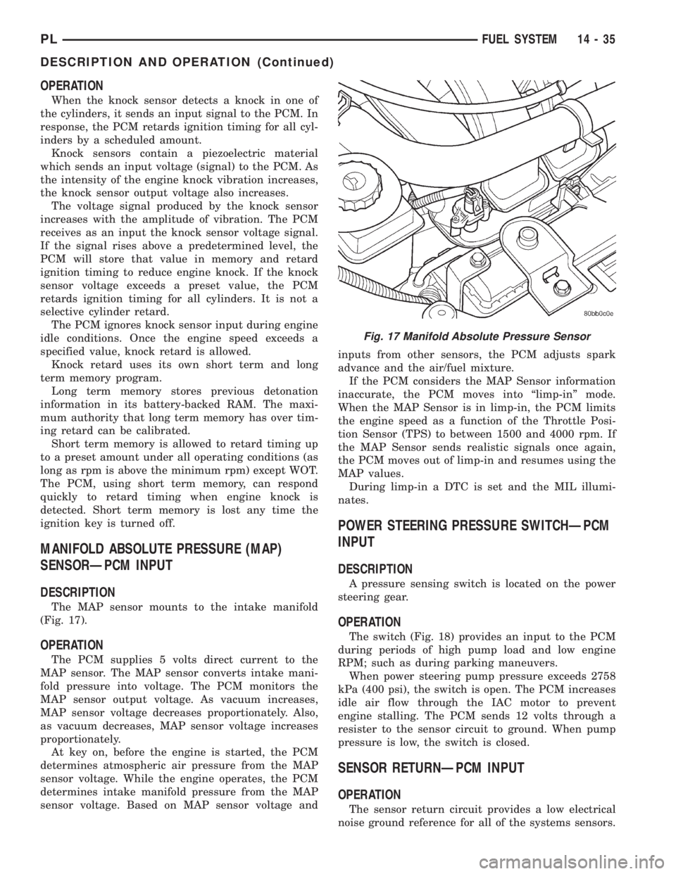
The MAP sensor mounts to the intake manifold
(Fig. 17).
OPERATION
The PCM supplies 5 volts direct current to the
MAP sensor. The MAP sensor converts intake mani-
fold pressure into voltage. The PCM monitors the
MAP sensor output voltage. As vacuum increases,
MAP sensor voltage decreases proportionately. Also,
as vacuum decreases, MAP sensor voltage increases
proportionately.
At key on, before the engine is started, the PCM
determines atmospheric air pressure from the MAP
sensor voltage. While the engine operates, the PCM
determines intake manifold pressure from the MAP
sensor voltage. Based on MAP sensor voltage andinputs from other sensors, the PCM adjusts spark
advance and the air/fuel mixture.
If the PCM considers the MAP Sensor information
inaccurate, the PCM moves into ªlimp-inº mode.
When the MAP Sensor is in limp-in, the PCM limits
the engine speed as a function of the Throttle Posi-
tion Sensor (TPS) to between 1500 and 4000 rpm. If
the MAP Sensor sends realistic signals once again,
the PCM moves out of limp-in and resumes using the
MAP values.
During limp-in a DTC is set and the MIL illumi-
nates.
POWER STEERING PRESSURE SWITCHÐPCM
INPUT
DESCRIPTION
A pressure sensing switch is located on the power
steering gear.
OPERATION
The switch (Fig. 18) provides an input to the PCM
during periods of high pump load and low engine
RPM; such as during parking maneuvers.
When power steering pump pressure exceeds 2758
kPa (400 psi), the switch is open. The PCM increases
idle air flow through the IAC motor to prevent
engine stalling. The PCM sends 12 volts through a
resister to the sensor circuit to ground. When pump
pressure is low, the switch is closed.
SENSOR RETURNÐPCM INPUT
OPERATION
The sensor return circuit provides a low electrical
noise ground reference for all of the systems sensors.
Fig. 17 Manifold Absolute Pressure Sensor
PLFUEL SYSTEM 14 - 35
DESCRIPTION AND OPERATION (Continued)
Page 858 of 1285
position of the throttle blade changes, the resistance
of the TPS changes.
OPERATION
The PCM supplies approximately 5 volts DC to the
TPS. The TPS output voltage (input signal to the
powertrain control module) represents throttle blade
position. The TPS output voltage to the PCM varies
from approximately 0.35 to 1.03 volts at minimum
throttle opening (idle) to a maximum of 3.1 to 4.0
volts at wide open throttle.
Along with inputs from other sensors, the PCM
uses the TPS input to determine current engine oper-
ating conditions. The PCM also adjusts fuel injector
pulse width and ignition timing based on these
inputs.
When the TPS indicates a voltage that is too high,
too low or not believable, the PCM sets a DTC. When
the DTC is set, the MIL is illuminated and the PCM
moves into limp-in mode. Limp-in for the TPS is
divided into three categories:
²Idle
²Part-throttle
²Wide open throttle (WOT)
VEHICLE SPEED SIGNAL (VSS)ÐPCM INPUT
DESCRIPTION
The PCM requires the VSS to be able to control
the following programs:
²Speed Control
²IAC motor (during deceleration)
²Injection pulse width (during deceleration)
²OBD II diagnostics
²PCM mileage EEPROM
²Road speed shutdown
²Speedometer/Odometer (bused message)NOTE: Road Speed Shutdown is the PCM shutting
off fuel injectors above a preset vehicle speed.
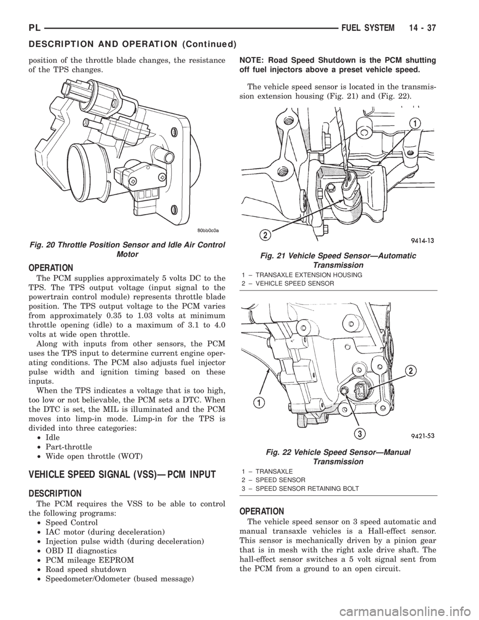
The vehicle speed sensor is located in the transmis-
sion extension housing (Fig. 21) and (Fig. 22).
OPERATION
The vehicle speed sensor on 3 speed automatic and
manual transaxle vehicles is a Hall-effect sensor.
This sensor is mechanically driven by a pinion gear
that is in mesh with the right axle drive shaft. The
hall-effect sensor switches a 5 volt signal sent from
the PCM from a ground to an open circuit.
Fig. 20 Throttle Position Sensor and Idle Air Control
Motor
Fig. 21 Vehicle Speed SensorÐAutomatic
Transmission
1 ± TRANSAXLE EXTENSION HOUSING
2 ± VEHICLE SPEED SENSOR
Fig. 22 Vehicle Speed SensorÐManual
Transmission
1 ± TRANSAXLE
2 ± SPEED SENSOR
3 ± SPEED SENSOR RETAINING BOLT
PLFUEL SYSTEM 14 - 37
DESCRIPTION AND OPERATION (Continued)