2000 DODGE NEON power steering fluid
[x] Cancel search: power steering fluidPage 888 of 1285
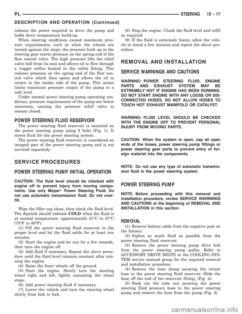
reduces the power required to drive the pump and
holds down temperature build-up.
When steering conditions exceed maximum pres-
sure requirements, such as when the wheels are
turned against the stops, the pressure built up in the
steering gear exerts pressure on the spring end of the
flow control valve. The high pressure lifts the relief
valve ball from its seat and allows oil to flow through
a trigger orifice located in the outlet fitting. This
reduces pressure on the spring end of the flow con-
trol valve which then opens and allows the oil to
return to the intake side of the pump. This action
limits maximum pressure output of the pump to a
safe level.
Under normal power steering pump operating con-
ditions, pressure requirements of the pump are below
maximum, causing the pressure relief valve to
remain closed.
POWER STEERING FLUID RESERVOIR
The power steering fluid reservoir is mounted on
the power steering pump using 3 bolts (Fig. 1). It
stores fluid for the power steering system.
The power steering fluid reservoir is considered an
integral part of the power steering pump and is not
serviced separately.
SERVICE PROCEDURES
POWER STEERING PUMP INITIAL OPERATION
CAUTION: The fluid level should be checked with
engine off to prevent injury from moving compo-
nents. Use only MoparTPower Steering Fluid. Do
not use automatic transmission fluid. Do not over-
fill.
Wipe the filler cap clean, then check the fluid level.
The dipstick should indicateCOLDwhen the fluid is
at normal temperature, approximately 21ÉC to 27ÉC
(70ÉF to 80ÉF).
(1) Fill the power steering fluid reservoir to the
proper level and let the fluid settle for at least two
minutes.
(2) Start the engine and let run for a few seconds,
then turn the engine off.
(3) Add fluid if necessary. Repeat the above proce-
dure until the fluid level remains constant after run-
ning the engine.
(4) Raise the front wheels off the ground.
(5) Start the engine. Slowly turn the steering
wheel right and left, lightly contacting the wheel
stops.
(6) Add power steering fluid if necessary.
(7) Lower the vehicle and turn the steering wheel
slowly from lock to lock.(8) Stop the engine. Check the fluid level and refill
as required.
(9) If the fluid is extremely foamy, allow the vehi-
cle to stand a few minutes and repeat the above pro-
cedure.
REMOVAL AND INSTALLATION
SERVICE WARNINGS AND CAUTIONS
WARNING: POWER STEERING FLUID, ENGINE
PARTS AND EXHAUST SYSTEM MAY BE
EXTREMELY HOT IF ENGINE HAS BEEN RUNNING.
DO NOT START ENGINE WITH ANY LOOSE OR DIS-
CONNECTED HOSES. DO NOT ALLOW HOSES TO
TOUCH HOT EXHAUST MANIFOLD OR CATALYST.
WARNING: FLUID LEVEL SHOULD BE CHECKED
WITH THE ENGINE OFF TO PREVENT PERSONAL
INJURY FROM MOVING PARTS.
CAUTION: When the system is open, cap all open
ends of the hoses, power steering pump fittings or
power steering gear ports to prevent entry of for-
eign material into the components.
NOTE: Do not use any type of automatic transmis-
sion fluid in the power steering system.
POWER STEERING PUMP
NOTE: Before proceeding with this removal and
installation procedure, review SERVICE WARNINGS
AND CAUTIONS at the beginning of REMOVAL AND
INSTALLATION in this section.
REMOVAL
(1) Remove battery cable from the negative post on
the battery.
(2) Siphon as much fluid as possible from the
power steering fluid reservoir.
(3) Remove the power steering pump drive belt
from the power steering pump pulley. Refer to
ACCESSORY DRIVE BELTS in the COOLING SYS-
TEM service manual group for the required removal
and installation procedure.
(4) Remove the hose clamp securing the return
hose to the power steering fluid reservoir. Slide the
hose off the end of the reservoir fitting. (Fig. 2).
(5) Back out the tube nut securing the power
steering fluid pressure hose to the power steering
pump and remove the hose from the pump (Fig. 2).
PLSTEERING 19 - 17
DESCRIPTION AND OPERATION (Continued)
Page 890 of 1285
SORY DRIVE BELTS in the COOLING SYSTEM
service manual group for the required removal and
installation procedure.
(6) Using a lint free towel, wipe clean all open
power steering hose ends and power steering pump
fittings.
(7) Install a new O-ring on the end of the power
steering pressure hose. Lubricate the O-ring using
clean power steering fluid.
(8) Attach the power steering fluid pressure hose
to the pressure fitting on the lower end of the power
steering pump (Fig. 2). Thread the tube nut securing
the power steering fluid pressure hose into the power
steering pump pressure fitting. Tighten the tube nut
to at torque of 34 N´m (25 ft. lbs.).
(9) Slide the power steering fluid return hose onto
the fluid reservoir fitting (Fig. 2). Position the hose
clamp so it is installed on the hose past the bead
formed into the fluid reservoir fitting.
(10) Perform the POWER STEERING PUMP INI-
TIAL OPERATION service procedure found in this
section of this group to properly fill and bleed the
power steering system.
(11) Check for leaks.
DISASSEMBLY AND ASSEMBLY
POWER STEERING PUMP (PULLEY)
The only serviceable part of the power steering
pump is the pulley. The following procedure is for the
removal and installation of the pulley from the
pump.
The power steering pump must be removed from
the vehicle for power steering pump pulley service.
Refer to POWER STEERING PUMP in REMOVAL
AND INSTALLATION for the required procedure.
CAUTION: Use care when removing and installing
the power steering pump pulley. It is made of plas-
tic composite, except for the center shank. The spe-
cial tools are to be used in the shank area only as
described in the following procedure.
DISASSEMBLY
CAUTION: Do not hammer on the power steering
pump pulley or shaft to remove the power steering
pump pulley. This will damage the pulley and the
power steering pump.
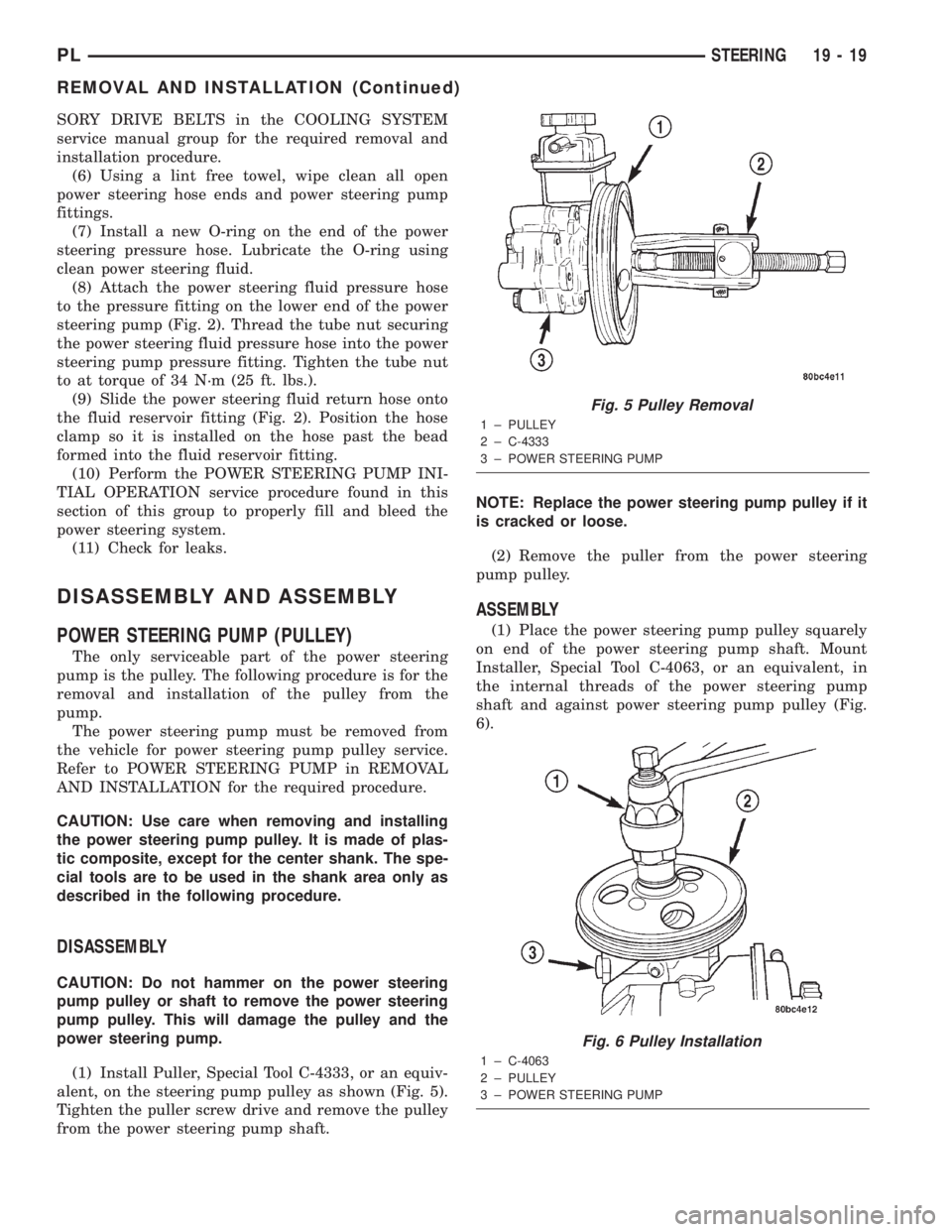
(1) Install Puller, Special Tool C-4333, or an equiv-
alent, on the steering pump pulley as shown (Fig. 5).
Tighten the puller screw drive and remove the pulley
from the power steering pump shaft.NOTE: Replace the power steering pump pulley if it
is cracked or loose.
(2) Remove the puller from the power steering
pump pulley.
ASSEMBLY
(1) Place the power steering pump pulley squarely
on end of the power steering pump shaft. Mount
Installer, Special Tool C-4063, or an equivalent, in
the internal threads of the power steering pump
shaft and against power steering pump pulley (Fig.
6).
Fig. 5 Pulley Removal
1 ± PULLEY
2 ± C-4333
3 ± POWER STEERING PUMP
Fig. 6 Pulley Installation
1 ± C-4063
2 ± PULLEY
3 ± POWER STEERING PUMP
PLSTEERING 19 - 19
REMOVAL AND INSTALLATION (Continued)
Page 891 of 1285
(2) Ensuring that the installer and the pulley
remain aligned with pump shaft, turn the installer
outer nut and force the pulley onto the power steer-
ing pump shaft until it is flush with the end of the
pump shaft. Once the pulley is flush with the end of
the shaft, the installer outer nut will no longer be
able to turn.
(3) Remove the installer from the power steering
pump.
(4) Install the power steering pump back on the
engine. Refer to POWER STEERING PUMP in
REMOVAL AND INSTALLATION for the required
procedure.
SPECIFICATIONS
POWER STEERING PUMP FLOW
SPECIFICATIONS
Power Steering Pump Flow:
At 1500 RPM And Minimum
Pressure . . 4.2 to 4.9 Liters/Min (1.1 to 1.3 GPM)
Control Valve Pressure
Relief.....9308 to 9998 kPa (1350 to 1450 psi)
POWER STEERING FASTENER TORQUE
SPECIFICATIONS
DESCRIPTION TORQUE
POWER STEERING HOSE:
Tube Nuts............... 34N´m(25ft.lbs.)
Hose Routing Clip Bolt.... 12N´m(105 in. lbs.)
POWER STEERING COOLER:
Mounting Screws.......... 10N´m(90in.lbs.)
POWER STEERING FLUID PRESSURE
SWITCH:
Switch................... 8N´m(70in.lbs.)
POWER STEERING PUMP:
Pressure Hose Tube Nut.... 34N´m(25ft.lbs.)
Pressure Fitting........... 88N´m(65ft.lbs.)
Front Mounting Bolts..... 28N´m(250 in. lbs.)
Rear Mounting Bolt....... 28N´m(250 in. lbs.)
Rear Support Bracket To Engine Bolts . . 54 N´m
(40 ft. lbs.)
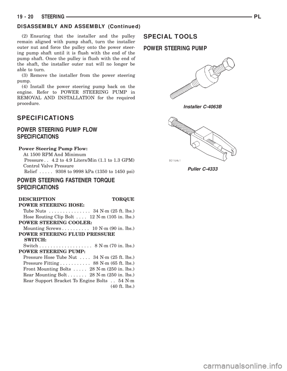
SPECIAL TOOLS
POWER STEERING PUMP
Installer C-4063B
Puller C-4333
19 - 20 STEERINGPL
DISASSEMBLY AND ASSEMBLY (Continued)
Page 892 of 1285
STEERING GEAR
TABLE OF CONTENTS
page page
DESCRIPTION AND OPERATION
POWER STEERING GEAR..................21
REMOVAL AND INSTALLATION
SERVICE WARNINGS AND CAUTIONS........22
POWER STEERING GEAR..................22
OUTER TIE ROD.........................26SPECIFICATIONS
POWER STEERING GEAR FASTENER
TORQUE SPECIFICATIONS...............28
SPECIAL TOOLS
POWER STEERING GEAR..................28
DESCRIPTION AND OPERATION
POWER STEERING GEAR
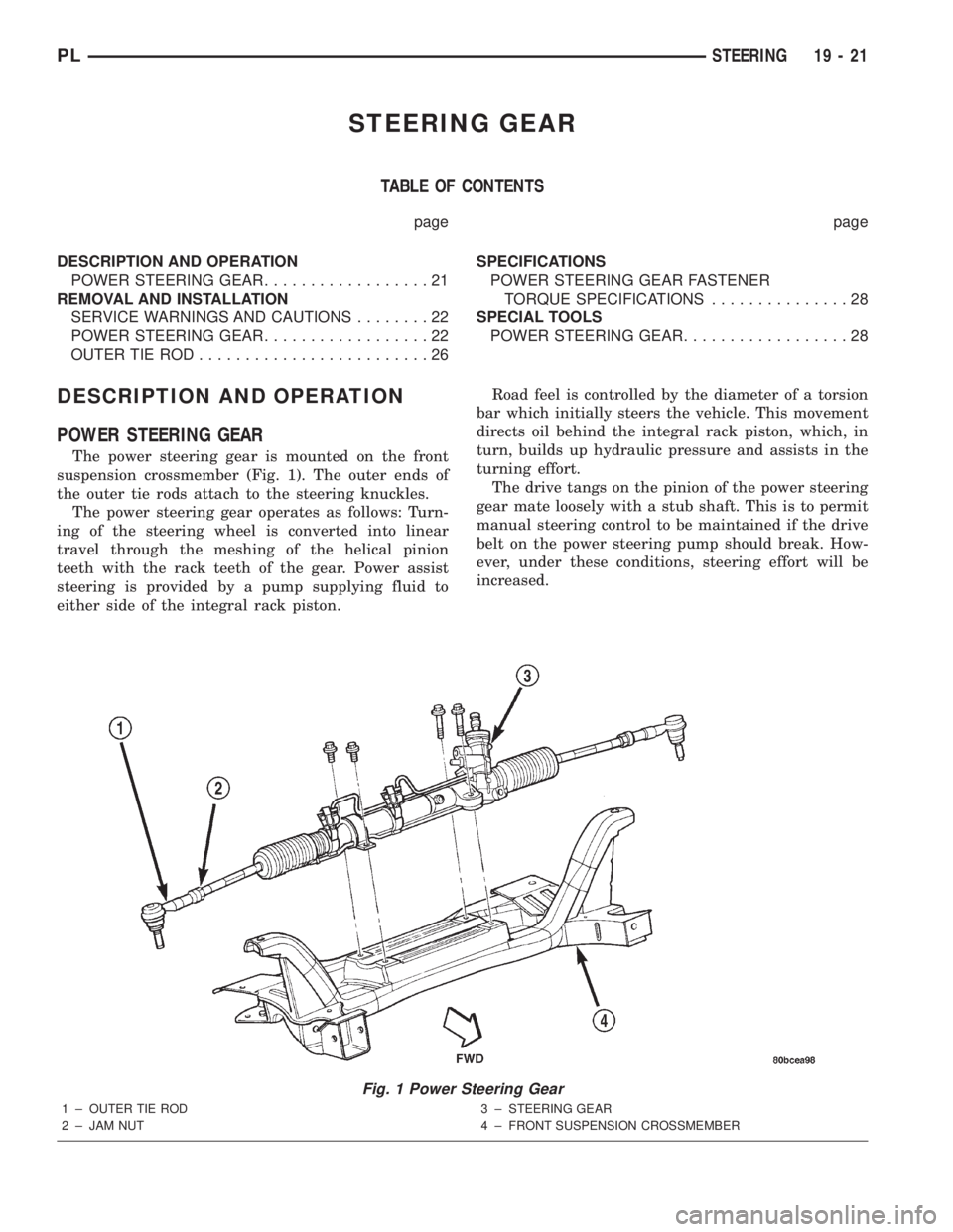
The power steering gear is mounted on the front
suspension crossmember (Fig. 1). The outer ends of
the outer tie rods attach to the steering knuckles.
The power steering gear operates as follows: Turn-
ing of the steering wheel is converted into linear
travel through the meshing of the helical pinion
teeth with the rack teeth of the gear. Power assist
steering is provided by a pump supplying fluid to
either side of the integral rack piston.Road feel is controlled by the diameter of a torsion
bar which initially steers the vehicle. This movement
directs oil behind the integral rack piston, which, in
turn, builds up hydraulic pressure and assists in the
turning effort.
The drive tangs on the pinion of the power steering
gear mate loosely with a stub shaft. This is to permit
manual steering control to be maintained if the drive
belt on the power steering pump should break. How-
ever, under these conditions, steering effort will be
increased.
Fig. 1 Power Steering Gear
1 ± OUTER TIE ROD
2 ± JAM NUT3 ± STEERING GEAR
4 ± FRONT SUSPENSION CROSSMEMBER
PLSTEERING 19 - 21
Page 893 of 1285
NOTE: The power steering gear should not be ser-
viced or adjusted. If a malfunction or oil leak occurs
with the steering gear, the complete steering gear
needs to be replaced.
REMOVAL AND INSTALLATION
SERVICE WARNINGS AND CAUTIONS
WARNING: POWER STEERING FLUID, ENGINE
PARTS AND EXHAUST SYSTEM MAY BE
EXTREMELY HOT IF ENGINE HAS BEEN RUNNING.
DO NOT START ENGINE WITH ANY LOOSE OR DIS-
CONNECTED HOSES. DO NOT ALLOW HOSES TO
TOUCH HOT EXHAUST MANIFOLD OR CATALYST.
WARNING: FLUID LEVEL SHOULD BE CHECKED
WITH THE ENGINE OFF TO PREVENT PERSONAL
INJURY FROM MOVING PARTS.
CAUTION: When the system is open, cap all open
ends of the hoses, power steering pump fittings or
power steering gear ports to prevent entry of for-
eign material into the components.
NOTE: Do not use any type of automatic transmis-
sion fluid in the power steering system.
POWER STEERING GEAR
NOTE: Before proceeding with this removal and
installation procedure, review SERVICE WARNINGS
AND CAUTIONS at the beginning of REMOVAL AND
INSTALLATION in this section.
REMOVAL
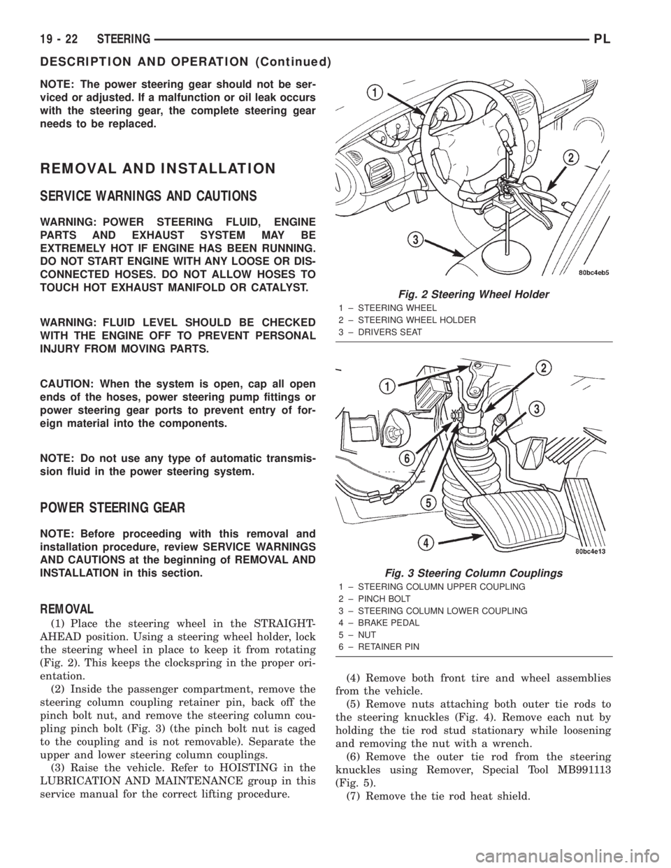
(1) Place the steering wheel in the STRAIGHT-
AHEAD position. Using a steering wheel holder, lock
the steering wheel in place to keep it from rotating
(Fig. 2). This keeps the clockspring in the proper ori-
entation.
(2) Inside the passenger compartment, remove the
steering column coupling retainer pin, back off the
pinch bolt nut, and remove the steering column cou-
pling pinch bolt (Fig. 3) (the pinch bolt nut is caged
to the coupling and is not removable). Separate the
upper and lower steering column couplings.
(3) Raise the vehicle. Refer to HOISTING in the
LUBRICATION AND MAINTENANCE group in this
service manual for the correct lifting procedure.(4) Remove both front tire and wheel assemblies
from the vehicle.
(5) Remove nuts attaching both outer tie rods to
the steering knuckles (Fig. 4). Remove each nut by
holding the tie rod stud stationary while loosening
and removing the nut with a wrench.
(6) Remove the outer tie rod from the steering
knuckles using Remover, Special Tool MB991113
(Fig. 5).
(7) Remove the tie rod heat shield.
Fig. 2 Steering Wheel Holder
1 ± STEERING WHEEL
2 ± STEERING WHEEL HOLDER
3 ± DRIVERS SEAT
Fig. 3 Steering Column Couplings
1 ± STEERING COLUMN UPPER COUPLING
2 ± PINCH BOLT
3 ± STEERING COLUMN LOWER COUPLING
4 ± BRAKE PEDAL
5 ± NUT
6 ± RETAINER PIN
19 - 22 STEERINGPL
DESCRIPTION AND OPERATION (Continued)
Page 894 of 1285
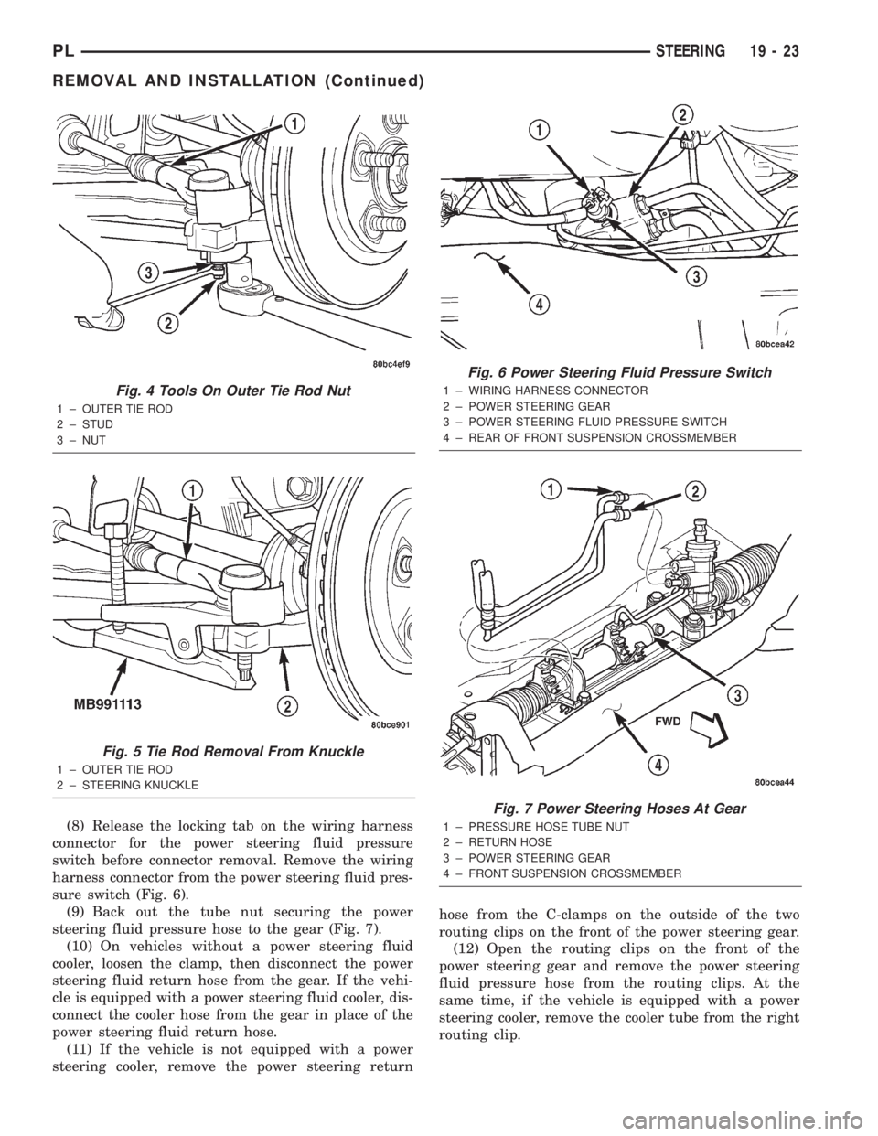
(8) Release the locking tab on the wiring harness
connector for the power steering fluid pressure
switch before connector removal. Remove the wiring
harness connector from the power steering fluid pres-
sure switch (Fig. 6).
(9) Back out the tube nut securing the power
steering fluid pressure hose to the gear (Fig. 7).
(10) On vehicles without a power steering fluid
cooler, loosen the clamp, then disconnect the power
steering fluid return hose from the gear. If the vehi-
cle is equipped with a power steering fluid cooler, dis-
connect the cooler hose from the gear in place of the
power steering fluid return hose.
(11) If the vehicle is not equipped with a power
steering cooler, remove the power steering returnhose from the C-clamps on the outside of the two
routing clips on the front of the power steering gear.
(12) Open the routing clips on the front of the
power steering gear and remove the power steering
fluid pressure hose from the routing clips. At the
same time, if the vehicle is equipped with a power
steering cooler, remove the cooler tube from the right
routing clip.
Fig. 4 Tools On Outer Tie Rod Nut
1 ± OUTER TIE ROD
2 ± STUD
3 ± NUT
Fig. 5 Tie Rod Removal From Knuckle
1 ± OUTER TIE ROD
2 ± STEERING KNUCKLE
Fig. 6 Power Steering Fluid Pressure Switch
1 ± WIRING HARNESS CONNECTOR
2 ± POWER STEERING GEAR
3 ± POWER STEERING FLUID PRESSURE SWITCH
4 ± REAR OF FRONT SUSPENSION CROSSMEMBER
Fig. 7 Power Steering Hoses At Gear
1 ± PRESSURE HOSE TUBE NUT
2 ± RETURN HOSE
3 ± POWER STEERING GEAR
4 ± FRONT SUSPENSION CROSSMEMBER
PLSTEERING 19 - 23
REMOVAL AND INSTALLATION (Continued)
Page 895 of 1285
(13) If the vehicle is equipped with a power steer-
ing fluid cooler, remove the two screws securing the
cooler to the front suspension crossmember. They are
located behind the cooler and can be accessed from
above. Allow the cooler to hang out of the way.
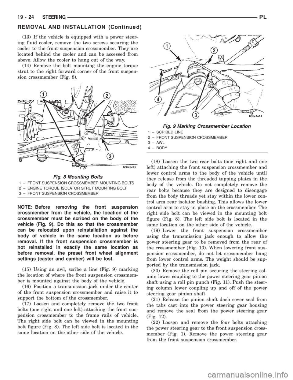
(14) Remove the bolt mounting the engine torque
strut to the right forward corner of the front suspen-
sion crossmember (Fig. 8).
NOTE: Before removing the front suspension
crossmember from the vehicle, the location of the
crossmember must be scribed on the body of the
vehicle (Fig. 9). Do this so that the crossmember
can be relocated upon reinstallation against the
body of vehicle in the same location as before
removal. If the front suspension crossmember is
not reinstalled in exactly the same location as
before removal, the preset front wheel alignment
settings (caster and camber) will be lost.
(15) Using an awl, scribe a line (Fig. 9) marking
the location of where the front suspension crossmem-
ber is mounted against the body of the vehicle.
(16) Position a transmission jack under the center
of the front suspension crossmember and raise it to
support the bottom of the crossmember.
(17) Loosen and completely remove the two front
bolts (one right and one left) attaching the front sus-
pension crossmember to the frame rails of vehicle.
The right side bolt can be viewed in the mounting
bolt figure (Fig. 8). The left side bolt is located in the
same location on the other side of the vehicle.(18) Loosen the two rear bolts (one right and one
left) attaching the front suspension crossmember and
lower control arms to the body of the vehicle until
they release from the threaded tapping plates in the
body of the vehicle. Do not completely remove the
rear bolts because they are designed to disengage
from the body threads yet stay within the lower con-
trol arm rear isolator bushing. This allows the lower
control arm to stay in place on the crossmember. The
right side bolt can be viewed in the mounting bolt
figure (Fig. 8). The left side bolt is located in the
same location on the other side of the vehicle.
(19) Lower the front suspension crossmember
using the transmission jack enough to allow the
power steering gear to be removed from the rear of
the crossmember (Fig. 10). When lowering front sus-
pension crossmember, do not let crossmember hang
from lower control arms. The weight should be sup-
ported by the transmission jack.
(20) Remove the roll pin securing the steering col-
umn lower coupling to the power steering gear pinion
shaft using a roll pin punch (Fig. 11). Push the steer-
ing column lower coupling up and off of the power
steering gear pinion shaft.
(21) Release the pinion shaft dash cover seal from
the tabs cast into the power steering gear housing
and remove the seal from the power steering gear
(Fig. 12).
(22) Loosen and remove the four bolts attaching
the power steering gear to the front suspension cross-
member (Fig. 1). Remove the power steering gear
from the front suspension crossmember.
Fig. 8 Mounting Bolts
1 ± FRONT SUSPENSION CROSSMEMBER MOUNTING BOLTS
2 ± ENGINE TORQUE ISOLATOR STRUT MOUNTING BOLT
3 ± FRONT SUSPENSION CROSSMEMBER
Fig. 9 Marking Crossmember Location
1 ± SCRIBED LINE
2 ± FRONT SUSPENSION CROSSMEMBER
3±AWL
4 ± BODY
19 - 24 STEERINGPL
REMOVAL AND INSTALLATION (Continued)
Page 897 of 1285
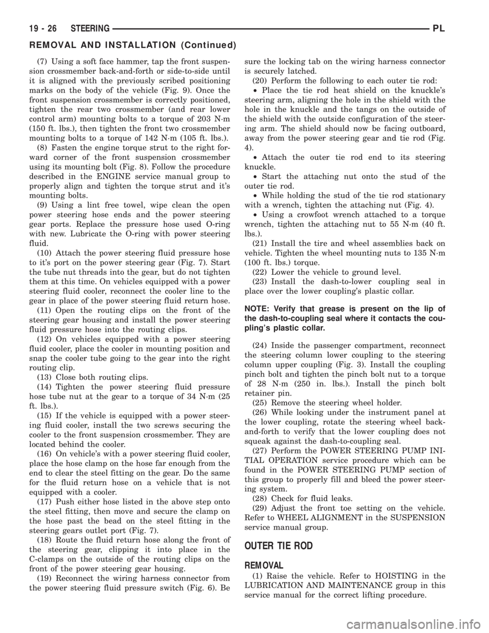
(7) Using a soft face hammer, tap the front suspen-
sion crossmember back-and-forth or side-to-side until
it is aligned with the previously scribed positioning
marks on the body of the vehicle (Fig. 9). Once the
front suspension crossmember is correctly positioned,
tighten the rear two crossmember (and rear lower
control arm) mounting bolts to a torque of 203 N´m
(150 ft. lbs.), then tighten the front two crossmember
mounting bolts to a torque of 142 N´m (105 ft. lbs.).
(8) Fasten the engine torque strut to the right for-
ward corner of the front suspension crossmember
using its mounting bolt (Fig. 8). Follow the procedure
described in the ENGINE service manual group to
properly align and tighten the torque strut and it's
mounting bolts.
(9) Using a lint free towel, wipe clean the open
power steering hose ends and the power steering
gear ports. Replace the pressure hose used O-ring
with new. Lubricate the O-ring with power steering
fluid.
(10) Attach the power steering fluid pressure hose
to it's port on the power steering gear (Fig. 7). Start
the tube nut threads into the gear, but do not tighten
them at this time. On vehicles equipped with a power
steering fluid cooler, reconnect the cooler line to the
gear in place of the power steering fluid return hose.
(11) Open the routing clips on the front of the
steering gear housing and install the power steering
fluid pressure hose into the routing clips.
(12) On vehicles equipped with a power steering
fluid cooler, place the cooler in mounting position and
snap the cooler tube going to the gear into the right
routing clip.
(13) Close both routing clips.
(14) Tighten the power steering fluid pressure
hose tube nut at the gear to a torque of 34 N´m (25
ft. lbs.).
(15) If the vehicle is equipped with a power steer-
ing fluid cooler, install the two screws securing the
cooler to the front suspension crossmember. They are
located behind the cooler.
(16) On vehicle's with a power steering fluid cooler,
place the hose clamp on the hose far enough from the
end to clear the steel fitting on the gear. Do the same
for the fluid return hose on a vehicle that is not
equipped with a cooler.
(17) Push either hose listed in the above step onto
the steel fitting, then move and secure the clamp on
the hose past the bead on the steel fitting in the
steering gears outlet port (Fig. 7).
(18) Route the fluid return hose along the front of
the steering gear, clipping it into place in the
C-clamps on the outside of the routing clips on the
front of the power steering gear housing.
(19) Reconnect the wiring harness connector from
the power steering fluid pressure switch (Fig. 6). Besure the locking tab on the wiring harness connector
is securely latched.
(20) Perform the following to each outer tie rod:
²Place the tie rod heat shield on the knuckle's
steering arm, aligning the hole in the shield with the
hole in the knuckle and the tangs on the outside of
the shield with the outside configuration of the steer-
ing arm. The shield should now be facing outboard,
away from the power steering gear and tie rod (Fig.
4).
²Attach the outer tie rod end to its steering
knuckle.
²Start the attaching nut onto the stud of the
outer tie rod.
²While holding the stud of the tie rod stationary
with a wrench, tighten the attaching nut (Fig. 4).
²Using a crowfoot wrench attached to a torque
wrench, tighten the attaching nut to 55 N´m (40 ft.
lbs.).
(21) Install the tire and wheel assemblies back on
vehicle. Tighten the wheel mounting nuts to 135 N´m
(100 ft. lbs.) torque.
(22) Lower the vehicle to ground level.
(23) Install the dash-to-lower coupling seal in
place over the lower coupling's plastic collar.
NOTE: Verify that grease is present on the lip of
the dash-to-coupling seal where it contacts the cou-
pling's plastic collar.
(24) Inside the passenger compartment, reconnect
the steering column lower coupling to the steering
column upper coupling (Fig. 3). Install the coupling
pinch bolt and tighten the pinch bolt nut to a torque
of 28 N´m (250 in. lbs.). Install the pinch bolt
retainer pin.
(25) Remove the steering wheel holder.
(26) While looking under the instrument panel at
the lower coupling, rotate the steering wheel back-
and-forth to verify that the lower coupling does not
squeak against the dash-to-coupling seal.
(27) Perform the POWER STEERING PUMP INI-
TIAL OPERATION service procedure which can be
found in the POWER STEERING PUMP section of
this group to properly fill and bleed the power steer-
ing system.
(28) Check for fluid leaks.
(29) Adjust the front toe setting on the vehicle.
Refer to WHEEL ALIGNMENT in the SUSPENSION
service manual group.
OUTER TIE ROD
REMOVAL
(1) Raise the vehicle. Refer to HOISTING in the
LUBRICATION AND MAINTENANCE group in this
service manual for the correct lifting procedure.
19 - 26 STEERINGPL
REMOVAL AND INSTALLATION (Continued)