2000 DODGE NEON Air conditioner
[x] Cancel search: Air conditionerPage 190 of 1285

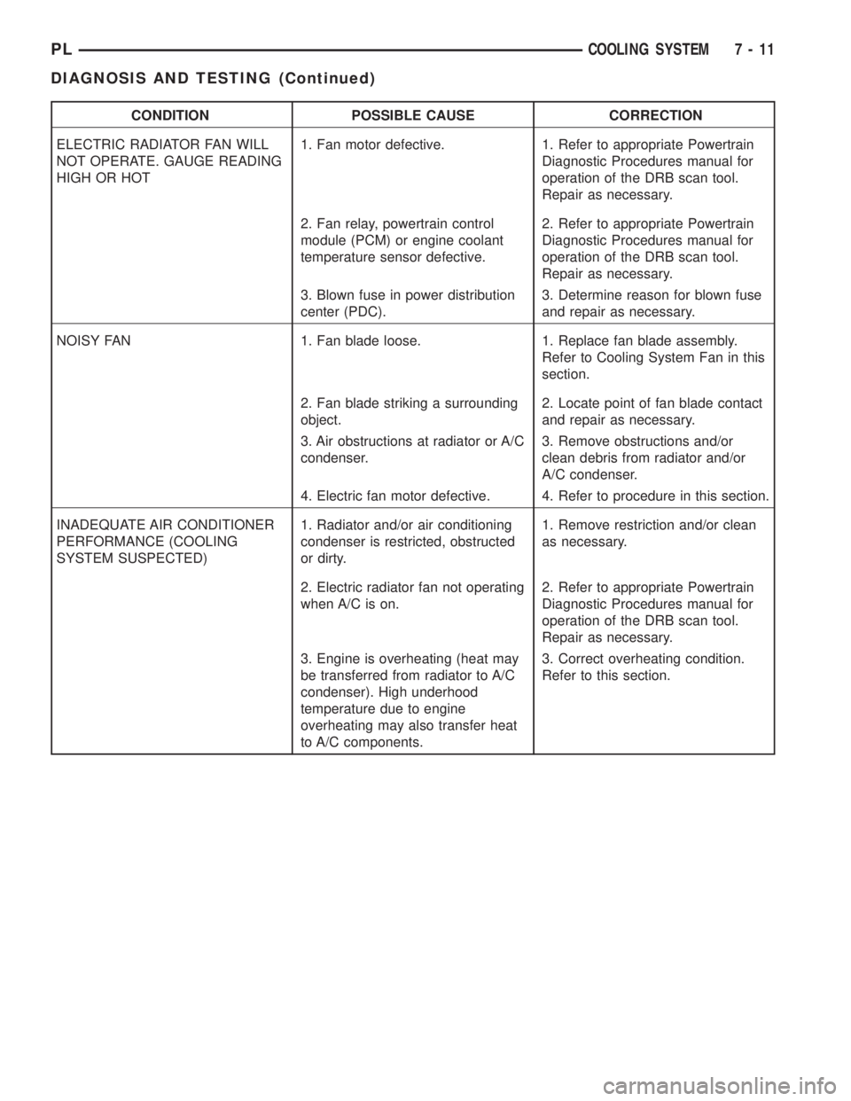
CONDITION POSSIBLE CAUSE CORRECTION
ELECTRIC RADIATOR FAN WILL
NOT OPERATE. GAUGE READING
HIGH OR HOT1. Fan motor defective. 1. Refer to appropriate Powertrain
Diagnostic Procedures manual for
operation of the DRB scan tool.
Repair as necessary.
2. Fan relay, powertrain control
module (PCM) or engine coolant
temperature sensor defective.2. Refer to appropriate Powertrain
Diagnostic Procedures manual for
operation of the DRB scan tool.
Repair as necessary.
3. Blown fuse in power distribution
center (PDC).3. Determine reason for blown fuse
and repair as necessary.
NOISY FAN 1. Fan blade loose. 1. Replace fan blade assembly.
Refer to Cooling System Fan in this
section.
2. Fan blade striking a surrounding
object.2. Locate point of fan blade contact
and repair as necessary.
3. Air obstructions at radiator or A/C
condenser.3. Remove obstructions and/or
clean debris from radiator and/or
A/C condenser.
4. Electric fan motor defective. 4. Refer to procedure in this section.
INADEQUATE AIR CONDITIONER
PERFORMANCE (COOLING
SYSTEM SUSPECTED)1. Radiator and/or air conditioning
condenser is restricted, obstructed
or dirty.1. Remove restriction and/or clean
as necessary.
2. Electric radiator fan not operating
when A/C is on.2. Refer to appropriate Powertrain
Diagnostic Procedures manual for
operation of the DRB scan tool.
Repair as necessary.
3. Engine is overheating (heat may
be transferred from radiator to A/C
condenser). High underhood
temperature due to engine
overheating may also transfer heat
to A/C components.3. Correct overheating condition.
Refer to this section.
PLCOOLING SYSTEM 7 - 11
DIAGNOSIS AND TESTING (Continued)
Page 348 of 1285

DIAGNOSIS AND TESTING
AIRBAG SYSTEM
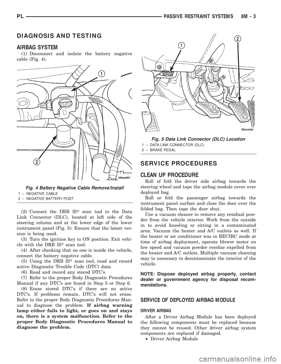
(1) Disconnect and isolate the battery negative
cable (Fig. 4).
(2) Connect the DRB llltscan tool to the Data
Link Connector (DLC), located at left side of the
steering column and at the lower edge of the lower
instrument panel (Fig. 5). Ensure that the latest ver-
sion is being used.
(3) Turn the ignition key to ON position. Exit vehi-
cle with the DRB llltscan tool.
(4) After checking that no one is inside the vehicle,
connect the battery negative cable.
(5) Using the DRB llltscan tool, read and record
active Diagnostic Trouble Code (DTC) data.
(6) Read and record any stored DTC's.
(7) Refer to the proper Body Diagnostic Procedures
Manual if any DTC's are found in Step 5 or Step 6.
(8) Erase stored DTC's if there are no active
DTC's. If problems remain, DTC's will not erase.
Refer to the proper Body Diagnostic Procedures Man-
ual to diagnose the problem.If airbag warning
lamp either fails to light, or goes on and stays
on, there is a system malfunction. Refer to the
proper Body Diagnostic Procedures Manual to
diagnose the problem.
SERVICE PROCEDURES
CLEAN UP PROCEDURE
Roll of fold the driver side airbag towards the
steering wheel and tape the airbag module cover over
deployed bag.
Roll or fold the passenger airbag towards the
instrument panel surface and close the door over the
folded bag. Then tape the door shut.
Use a vacuum cleaner to remove any residual pow-
der from the vehicle interior. Work from the outside
in to avoid kneeling or sitting in a contaminated
area. Vacuum the heater and A/C outlets as well. If
the heater or air conditioner was in RECIRC mode at
time of airbag deployment, operate blower motor on
low speed and vacuum powder residue expelled from
the heater and A/C outlets. Multiple vacuum cleaning
may to necessary to decontaminate the interior of the
vehicle.
NOTE: Dispose deployed airbag properly, contact
dealer or government agency for disposal recom-
mendations.
SERVICE OF DEPLOYED AIRBAG MODULE
DRIVER AIRBAG
After a Driver Airbag Module has been deployed
the following components must be replaced because
they cannot be reused. Other driver airbag system
components are replaced if damaged.
²Driver Airbag Module
Fig. 4 Battery Negative Cable Remove/Install
1 ± NEGATIVE CABLE
2 ± NEGATIVE BATTERY POST
Fig. 5 Data Link Connector (DLC) Location
1 ± DATA LINK CONNECTOR (DLC)
2 ± BRAKE PEDAL
PLPASSIVE RESTRAINT SYSTEMS 8M - 3
Page 1234 of 1285

It is also important to keep the air intake openings
clear of debris because leaf particles and other debris
that is small enough to pass through the cowl ple-
num screen can accumulate within the heater-A/C
housing. The closed, warm, damp and dark environ-
ment created within the heater-A/C housing is ideal
for the growth of certain molds, mildews and other
fungi. Any accumulation of decaying plant matter
provides an additional food source for fungal spores,
which enter the housing with the fresh air. Excess
debris, as well as objectionable odors created by
decaying plant matter and growing fungi can be dis-
charged into the passenger compartment during
heater-A/C system operation.
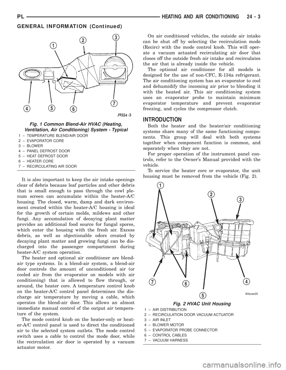
The heater and optional air conditioner are blend-
air type systems. In a blend-air system, a blend-air
door controls the amount of unconditioned air (or
cooled air from the evaporator on models with air
conditioning) that is allowed to flow through, or
around, the heater core. A temperature control knob
on the heater-A/C control panel determines the dis-
charge air temperature by moving a cable, which
operates the blend-air door. This allows an almost
immediate manual control of the output air tempera-
ture of the system.
The mode control knob on the heater-only or heat-
er-A/C control panel is used to direct the conditioned
air to the selected system outlets. The mode control
switch uses a cable to control the mode door, while
the recirculation air door is operated by a vacuum
actuator motor.On air conditioned vehicles, the outside air intake
can be shut off by selecting the recirculation mode
(Recirc) with the mode control knob. This will oper-
ate a vacuum actuated recirculating air door that
closes off the outside fresh air intake and recirculates
the air that is already inside the vehicle.
The optional air conditioner for all models is
designed for the use of non-CFC, R-134a refrigerant.
The air conditioning system has an evaporator to cool
and dehumidify the incoming air prior to blending it
with the heated air. This air conditioning system
uses an evaporator probe to maintain minimum
evaporator temperature and prevent evaporator
freezing, and cycles the compressor clutch.
INTRODUCTION
Both the heater and the heater/air conditioning
systems share many of the same functioning compo-
nents. This group will deal with both systems
together when component function is common, and
separately when they are not.
For proper operation of the instrument panel con-
trols, refer to the Owner's Manual provided with the
vehicle.
To service the heater core or evaporator, the unit
housing must be removed from the vehicle (Fig. 2).Fig. 1 Common Blend-Air HVAC (Heating,
Ventilation, Air Conditioning) System - Typical
1 ± TEMPERATURE BLEND/AIR DOOR
2 ± EVAPORATOR CORE
3 ± BLOWER
4 ± PANEL DEFROST DOOR
5 ± HEAT DEFROST DOOR
6 ± HEATER CORE
7 ± RECIRCULATING AIR DOOR
Fig. 2 HVAC Unit Housing
1 ± AIR DISTRIBUTION
2 ± RECIRCULATION DOOR VACUUM ACTUATOR
3 ± AIR INLET
4 ± BLOWER MOTOR
5 ± EVAPORATOR PROBE CONNECTOR
6 ± CONTROL CABLES
7 ± VACUUM HARNESS
PLHEATING AND AIR CONDITIONING 24 - 3
GENERAL INFORMATION (Continued)
Page 1249 of 1285

CAUTION: Do not overcharge refrigerant system,
as excessive compressor head pressure can cause
noise and system failure.
After the system has been tested for leaks and
evacuated, a refrigerant (R-134a) charge can be
injected into the system.
NOTE: When connecting the service equipment
coupling to the line fitting, verify that the valve of
the coupling is fully closed. This will reduce the
amount of effort required to make the connection.
(1) If using a separate vacuum pump close all
valves before disconnecting pump. Connect manifold
gauge set to the A/C service ports (Fig. 16).
NOTE: The air conditioning system in this vehicle
holds (27 oz. or 1.69 lbs.) of R-134a refrigerant.
(2) Measure refrigerant (refer to capacities). Refer
to the instructions provided with the equipment
being used.
(3) Verify engine is shut off. Open the suction and
discharge valves. Open the charge valve to allow the
refrigerant to flow into the system. When the trans-
fer of refrigerant has stopped, close the suction and
discharge valve.
(4) If all of the charge did not transfer from the
dispensing device, put vehicle controls into the fol-
lowing mode:
²Automatic transaxle in park or manual tran-
saxle in neutral
²Engine idling at 700 rpm
²A/C control set in 100 percent outside air
²Panel mode
²Blower motor ON high speed
²Vehicle windows closed
If the A/C compressor does not engage, test the
compressor clutch control circuit and correct any fail-
ure. Refer to Group 8W, Wiring Diagrams.
(5) Open the suction valve to allow the remaining
refrigerant to transfer to the system.
WARNING: TAKE CARE NOT TO OPEN THE DIS-
CHARGE (HIGH-PRESSURE) VALVE AT THIS TIME.
(6) Close all valves and test the A/C system perfor-
mance.
(7) Disconnect the charging station or manifold
gauge set. Install the service port caps.
EVACUATING REFRIGERANT SYSTEM
NOTE: Special effort must be used to prevent mois-
ture from entering the A/C system oil. Moisture in
the oil is very difficult to remove and will cause a
reliability problem with the compressor.If a compressor designed to use R-134a refrigerant
is left open to the atmosphere for an extended period
of time. It is recommended that the refrigerant oil be
drained and replaced with new oil or a new compres-
sor be used. This will eliminate the possibility of con-
taminating the refrigerant system.
If the refrigerant system has been open to the
atmosphere, it must be evacuated before the system
can be filled. Moisture and air mixed with the refrig-
erant will raise the compressor head pressure above
acceptable operating levels. This will reduce the per-
formance of the air conditioner and damage the com-
pressor. Moisture will boil at near room temperature
when exposed to vacuum. To evacuate the refrigerant
system:
NOTE: When connecting the service equipment
coupling to the line fitting, verify that the valve of
the coupling is fully closed. This will reduce the
amount of effort required to make the connection.
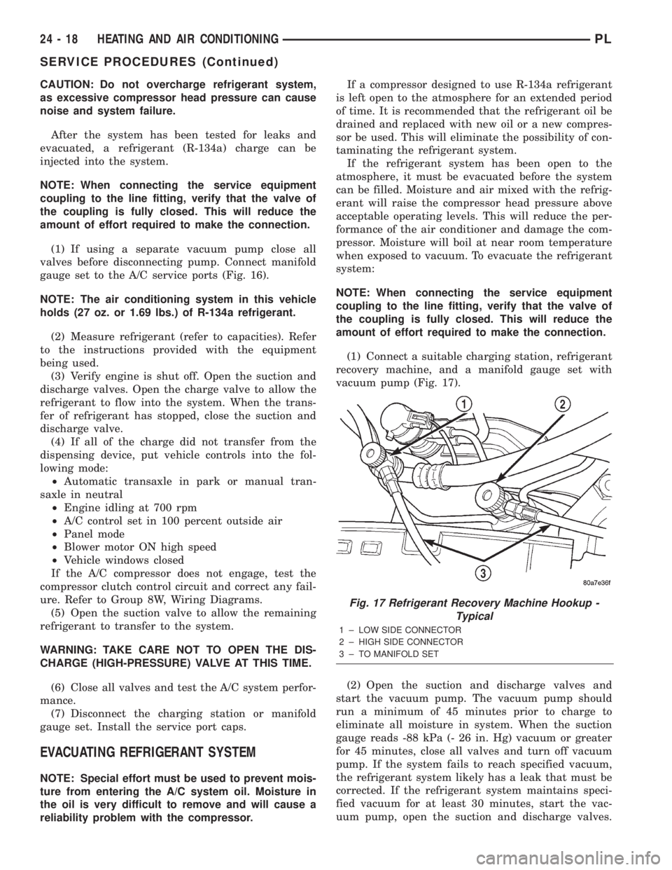
(1) Connect a suitable charging station, refrigerant
recovery machine, and a manifold gauge set with
vacuum pump (Fig. 17).
(2) Open the suction and discharge valves and
start the vacuum pump. The vacuum pump should
run a minimum of 45 minutes prior to charge to
eliminate all moisture in system. When the suction
gauge reads -88 kPa (- 26 in. Hg) vacuum or greater
for 45 minutes, close all valves and turn off vacuum
pump. If the system fails to reach specified vacuum,
the refrigerant system likely has a leak that must be
corrected. If the refrigerant system maintains speci-
fied vacuum for at least 30 minutes, start the vac-
uum pump, open the suction and discharge valves.
Fig. 17 Refrigerant Recovery Machine Hookup -
Typical
1 ± LOW SIDE CONNECTOR
2 ± HIGH SIDE CONNECTOR
3 ± TO MANIFOLD SET
24 - 18 HEATING AND AIR CONDITIONINGPL
SERVICE PROCEDURES (Continued)