2000 DODGE NEON heater core
[x] Cancel search: heater corePage 1109 of 1285
Pending ConditionsÐThere are not conditions
or situations that prompt conflict or suspension of
testing. The oxygen sensor heater test is not run
pending resolution of MIL illumination due to oxygen
sensor failure.
SuspendÐThere are no conditions which exist for
suspending the Heater Monitor.
CATALYST MONITOR
To comply with clean air regulations, vehicles are
equipped with catalytic converters. These converters
reduce the emission of hydrocarbons, oxides of nitro-
gen and carbon monoxide.
Normal vehicle miles or engine misfire can cause a
catalyst to decay. A meltdown of the ceramic core can
cause a reduction of the exhaust passage. This can
increase vehicle emissions and deteriorate engine
performance, driveability and fuel economy.
The catalyst monitor uses dual oxygen sensors
(O2S's) to monitor the efficiency of the converter. The
dual O2S strategy is based on the fact that as a cat-
alyst deteriorates, its oxygen storage capacity and its
efficiency are both reduced. By monitoring the oxy-
gen storage capacity of a catalyst, its efficiency can
be indirectly calculated. The upstream O2S is used to
detect the amount of oxygen in the exhaust gas
before the gas enters the catalytic converter. The
PCM calculates the A/F mixture from the output of
the O2S. A low voltage indicates high oxygen content
(lean mixture). A high voltage indicates a low content
of oxygen (rich mixture).
When the upstream O2S detects a lean condition,
there is an abundance of oxygen in the exhaust gas.
A functioning converter would store this oxygen so it
can use it for the oxidation of HC and CO. As the
converter absorbs the oxygen, there will be a lack of
oxygen downstream of the converter. The output of
the downstream O2S will indicate limited activity in
this condition.
As the converter loses the ability to store oxygen,
the condition can be detected from the behavior of
the downstream O2S. When the efficiency drops, no
chemical reaction takes place. This means the con-
centration of oxygen will be the same downstream as
upstream. The output voltage of the downstream
O2S copies the voltage of the upstream sensor. The
only difference is a time lag (seen by the PCM)
between the switching of the O2S's.
To monitor the system, the number of lean-to-rich
switches of upstream and downstream O2S's is
counted. The ratio of downstream switches to
upstream switches is used to determine whether the
catalyst is operating properly. An effective catalyst
will have fewer downstream switches than it has
upstream switches i.e., a ratio closer to zero. For atotally ineffective catalyst, this ratio will be one-to-
one, indicating that no oxidation occurs in the device.
The system must be monitored so that when cata-
lyst efficiency deteriorates and exhaust emissions
increase to over the legal limit, the MIL (check
engine lamp) will be illuminated.
Monitor OperationÐTo monitor catalyst effi-
ciency, the PCM expands the rich and lean switch
points of the heated oxygen sensor. With extended
switch points, the air/fuel mixture runs richer and
leaner to overburden the catalytic converter. Once
the test is started, the air/fuel mixture runs rich and
lean and the O2 switches are counted. A switch is
counted when an oxygen sensor signal goes from
below the lean threshold to above the rich threshold.
The number of Rear O2 sensor switches is divided by
the number of Front O2 sensor switches to determine
the switching ratio.
The test runs for 20 seconds. As catalyst efficiency
deteriorated over the life of the vehicle, the switch
rate at the downstream sensor approaches that of the
upstream sensor. If at any point during the test
period the switch ratio reaches a predetermined
value, a counter is incremented by one. The monitor
is enabled to run another test during that trip. When
the test fails three times, the counter increments to
three, a malfunction is entered, and a Freeze Frame
is stored. When the counter increments to three dur-
ing the next trip, the code is matured and the MIL is
illuminated. If the test passes the first, no further
testing is conducted during that trip.
The MIL is extinguished after three consecutive
good trips. The good trip criteria for the catalyst
monitor is more stringent than the failure criteria. In
order to pass the test and increment one good trip,
the downstream sensor switch rate must be less than
80% of the upstream rate (60% for manual transmis-
sions). The failure percentages are 90% and 70%
respectively.
Enabling ConditionsÐThe following conditions
must typically be met before the PCM runs the cat-
alyst monitor. Specific times for each parameter may
be different from engine to engine.
²Accumulated drive time
²Enable time
²Ambient air temperature
²Barometric pressure
²Catalyst warm-up counter
²Engine coolant temperature
²Accumulated throttle position sensor
²Vehicle speed
²MAP
²RPM
²Engine in closed loop
²Fuel level
25 - 22 EMISSION CONTROL SYSTEMSPL
DESCRIPTION AND OPERATION (Continued)
Page 1232 of 1285
HEATING AND AIR CONDITIONING
TABLE OF CONTENTS
page page
GENERAL INFORMATION
A/C APPLICATION TABLE...................2
HEATER AND AIR CONDITIONING CONTROL...2
HEATER AND AIR CONDITIONING............2
INTRODUCTION..........................3
SAFETY PRECAUTIONS AND WARNINGS......4
DESCRIPTION AND OPERATION
A/C REFRIGERANT LINES..................4
BLOWER MOTOR RESISTOR................5
COMPRESSOR...........................5
COMPRESSOR FRONT SHAFT SEAL..........6
CONDENSATION DRAIN TUBE...............6
ENGINE COOLING SYSTEM REQUIREMENTS...6
EVAPORATOR PROBE......................6
HANDLING TUBING AND FITTINGS...........6
HIGH PRESSURE CUT OUT SWITCH..........6
LOW PRESSURE CUT OFF SWITCH..........6
SIDE WINDOW DEMISTERS................7
SYSTEM AIRFLOW........................7
SYSTEM OIL LEVEL.......................7
VACUUM CONTROL SYSTEM................8
DIAGNOSIS AND TESTING
A/C PERFORMANCE TEST..................9
BLOWER MOTOR ELECTRICAL DIAGNOSIS....9
BLOWER MOTOR VIBRATION AND/OR
NOISE DIAGNOSIS.....................11
COMPRESSOR NOISE DIAGNOSIS..........11
EVAPORATOR PROBE TEST................11
EXPANSION VALVE.......................11
HEATER PERFORMANCE TEST.............13
LOW PRESSURE CUT OFF SWITCH.........14
SYSTEM CHARGE LEVEL TEST.............14
VACUUM CONTROL SYSTEM...............15
SERVICE PROCEDURES
CHARGING A/C SYSTEM..................17EVACUATING REFRIGERANT SYSTEM........18
R-134a REFRIGERANT....................19
SERVICING REFRIGERANT OIL LEVEL.......19
SYSTEM LEAK CHECKING.................20
REMOVAL AND INSTALLATION
A/C FILTER/DRIER.......................20
A/C SERVICE PORT VALVE CORES..........21
BLOWER MOTOR AND WHEEL ASSEMBLY....21
BLOWER MOTOR RESISTOR...............22
BLOWER MOTOR WHEEL.................22
COMPRESSOR..........................22
COMPRESSOR CLUTCH/COIL ASSEMBLY.....23
CONDENSATION DRAIN TUBE..............25
CONDENSER............................25
DISCHARGE LINE........................26
EVAPORATOR...........................26
EVAPORATOR PROBE.....................26
EXPANSION VALVE.......................27
HEATER CORE..........................28
HEATER HOSES.........................28
HIGH PRESSURE CUT OUT SWITCH.........29
HIGH PRESSURE RELIEF VALVE............29
LIQUID LINE............................29
LOW PRESSURE CUT OFF SWITCH.........29
MODE CONTROL CABLE..................30
RECIRCULATION DOOR ACTUATOR.........31
SUCTION LINE..........................31
TEMPERATURE CONTROL CABLE...........32
UNIT HOUSING..........................32
DISASSEMBLY AND ASSEMBLY
HEATER-A/C HOUSING....................34
ADJUSTMENTS
MODE CONTROL CABLE..................34
TEMPERATURE CONTROL CABLE...........34
PLHEATING AND AIR CONDITIONING 24 - 1
Page 1234 of 1285
It is also important to keep the air intake openings
clear of debris because leaf particles and other debris
that is small enough to pass through the cowl ple-
num screen can accumulate within the heater-A/C
housing. The closed, warm, damp and dark environ-
ment created within the heater-A/C housing is ideal
for the growth of certain molds, mildews and other
fungi. Any accumulation of decaying plant matter
provides an additional food source for fungal spores,
which enter the housing with the fresh air. Excess
debris, as well as objectionable odors created by
decaying plant matter and growing fungi can be dis-
charged into the passenger compartment during
heater-A/C system operation.
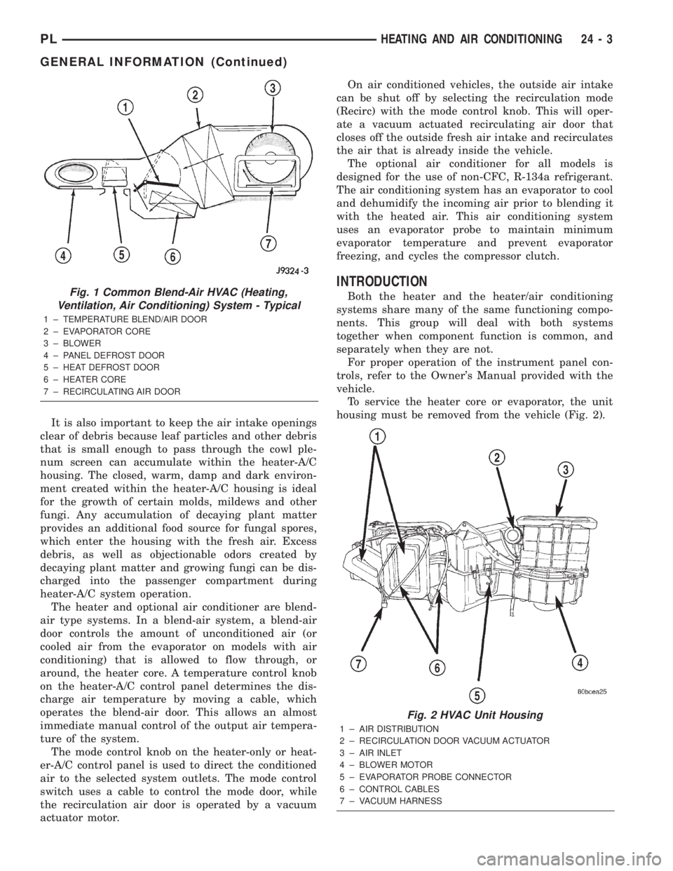
The heater and optional air conditioner are blend-
air type systems. In a blend-air system, a blend-air
door controls the amount of unconditioned air (or
cooled air from the evaporator on models with air
conditioning) that is allowed to flow through, or
around, the heater core. A temperature control knob
on the heater-A/C control panel determines the dis-
charge air temperature by moving a cable, which
operates the blend-air door. This allows an almost
immediate manual control of the output air tempera-
ture of the system.
The mode control knob on the heater-only or heat-
er-A/C control panel is used to direct the conditioned
air to the selected system outlets. The mode control
switch uses a cable to control the mode door, while
the recirculation air door is operated by a vacuum
actuator motor.On air conditioned vehicles, the outside air intake
can be shut off by selecting the recirculation mode
(Recirc) with the mode control knob. This will oper-
ate a vacuum actuated recirculating air door that
closes off the outside fresh air intake and recirculates
the air that is already inside the vehicle.
The optional air conditioner for all models is
designed for the use of non-CFC, R-134a refrigerant.
The air conditioning system has an evaporator to cool
and dehumidify the incoming air prior to blending it
with the heated air. This air conditioning system
uses an evaporator probe to maintain minimum
evaporator temperature and prevent evaporator
freezing, and cycles the compressor clutch.
INTRODUCTION
Both the heater and the heater/air conditioning
systems share many of the same functioning compo-
nents. This group will deal with both systems
together when component function is common, and
separately when they are not.
For proper operation of the instrument panel con-
trols, refer to the Owner's Manual provided with the
vehicle.
To service the heater core or evaporator, the unit
housing must be removed from the vehicle (Fig. 2).Fig. 1 Common Blend-Air HVAC (Heating,
Ventilation, Air Conditioning) System - Typical
1 ± TEMPERATURE BLEND/AIR DOOR
2 ± EVAPORATOR CORE
3 ± BLOWER
4 ± PANEL DEFROST DOOR
5 ± HEAT DEFROST DOOR
6 ± HEATER CORE
7 ± RECIRCULATING AIR DOOR
Fig. 2 HVAC Unit Housing
1 ± AIR DISTRIBUTION
2 ± RECIRCULATION DOOR VACUUM ACTUATOR
3 ± AIR INLET
4 ± BLOWER MOTOR
5 ± EVAPORATOR PROBE CONNECTOR
6 ± CONTROL CABLES
7 ± VACUUM HARNESS
PLHEATING AND AIR CONDITIONING 24 - 3
GENERAL INFORMATION (Continued)
Page 1238 of 1285
SIDE WINDOW DEMISTERS
The demisters direct air from the unit housing
through the outlets located on the top corners of the
instrument panel. The demisters operate when the
mode selector is anywhere between floor and defrost
settings. Some air may be noticeable from the demis-
ter outlets when the mode selector is in the bilevel to
floor positions.
SYSTEM AIRFLOW
The system pulls outside (ambient) air through the
cowl opening at the base of the windshield. Then it
goes into the plenum chamber above the unit hous-
ing. On air conditioned vehicles, the air passes
through the evaporator. Air flow can be directed
either through or around the heater core. This is
done by adjusting the blend-air door with the TEMP
control on the instrument panel. The air flow can
then be directed from the panel, floor and defrost
outlets in various combinations using the mode selec-
tor. There are 17 different mode selections possible.
Air flow velocity can be adjusted with the blower
speed selector switch on the instrument panel.
On A/C equipped vehicles the ambient air intake
can be controlled by opening and closing the recircu-
lating air door. When placed in RECIRC, air that is
inside vehicle is removed continuously and recircu-
lated through unit housing. Ambient air cannot be
controlled on vehicles without A/C. The system uses
outside air at all times.
The air conditioning compressor can be engaged by
turning the fan switch counterclockwise from the off
position. It can also be engaged by placing the mode
control in the mix to defrost positions. This will
remove heat and humidity from the air before it is
directed through or around the heater core.
SYSTEM OIL LEVEL
It is important to have the correct amount of oil in
the A/C system to ensure proper lubrication of the
compressor. Too little oil will result in damage to the
compressor. Too much oil will reduce the cooling
capacity of the system and consequently result in
higher discharge air temperatures.
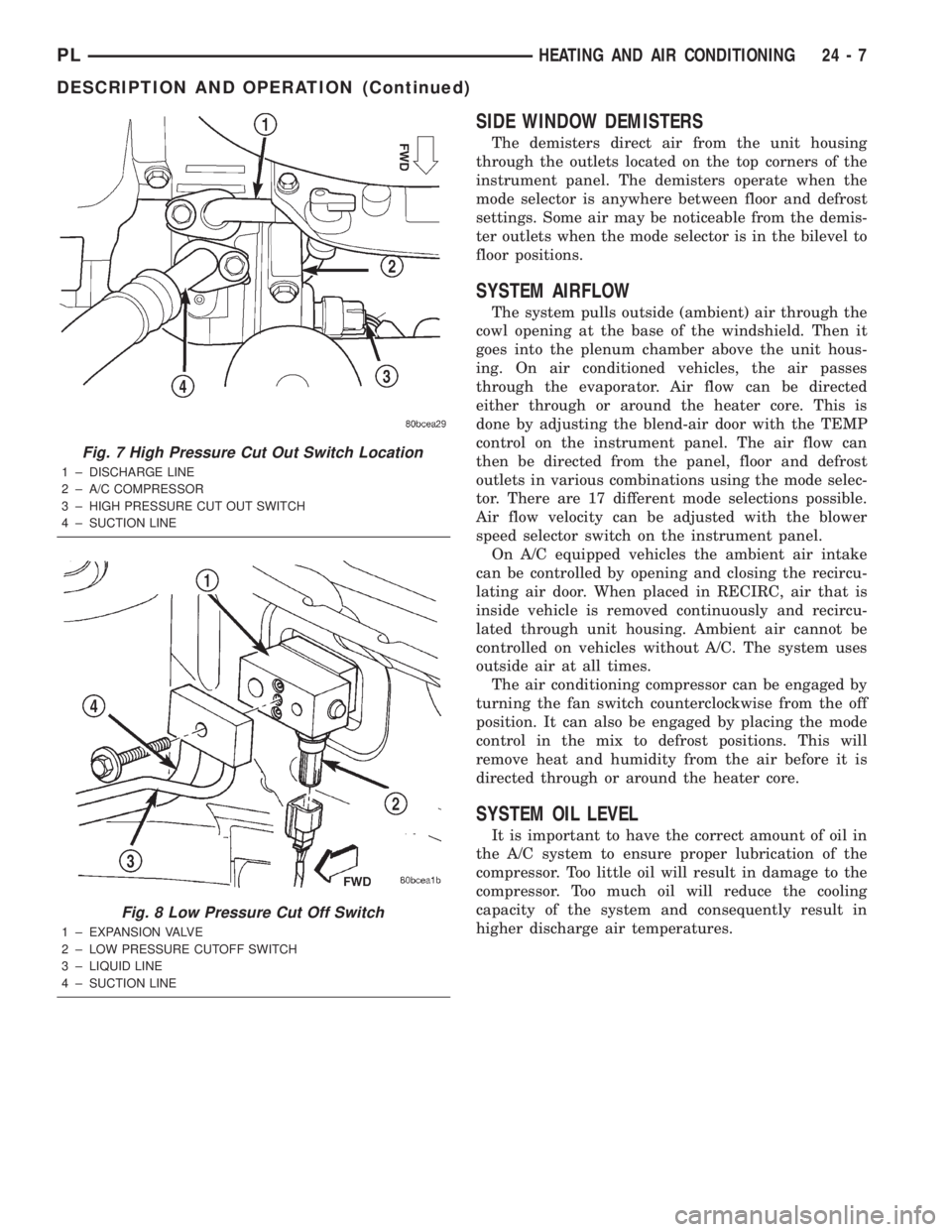
Fig. 7 High Pressure Cut Out Switch Location
1 ± DISCHARGE LINE
2 ± A/C COMPRESSOR
3 ± HIGH PRESSURE CUT OUT SWITCH
4 ± SUCTION LINE
Fig. 8 Low Pressure Cut Off Switch
1 ± EXPANSION VALVE
2 ± LOW PRESSURE CUTOFF SWITCH
3 ± LIQUID LINE
4 ± SUCTION LINE
PLHEATING AND AIR CONDITIONING 24 - 7
DESCRIPTION AND OPERATION (Continued)
Page 1245 of 1285
POSSIBLE LOCATIONS OR CAUSE OF
OBSTRUCTED COOLANT FLOW
(1) Pinched or kinked heater hoses.
(2) Improper heater hose routing.
(3) Plugged heater hoses or supply and return
ports at cooling system connections, refer to Group 7,
Cooling System.
(4) Plugged heater core.
(5) Air locked heater core.
(6) If coolant flow is verified and outlet tempera-
ture is insufficient, a mechanical problem may exist.
POSSIBLE LOCATION OR CAUSE OF INSUFFICIENT
HEAT
(1) Obstructed cowl air intake.
(2) Obstructed heater system outlets.
(3) Blend-air door not functioning properly.
TEMPERATURE CONTROL
If temperature cannot be adjusted with the TEMP
lever on the control panel, the following could require
service:
(1) Blend-air door binding.
(2) Faulty blend-air door cable.
(3) Improper engine coolant temperature.
(4) Faulty Instrument Panel Control.
LOW PRESSURE CUT OFF SWITCH
The work area must not be below 21ÉC (70ÉF) to
test the compressor clutch circuit.
(1) With gear selector in park or neutral and park
brake set, start engine and allow to idle.
(2) Raise hood and disconnect low pressure cut off
switch connector boot.
(3) Using a suitable jumper wire, jump across the
terminals inside wire connector boot.
(4) If the compressor clutch does not engage, the
cycling clutch switch, wiring, relay, or fuse can be
defective. Refer to Group 8W, Wiring Diagrams.
(5) If clutch engages, connect manifold gauge set.
Read low pressure gauge. At pressure above 97 kPa
(14 psi) and above, low pressure out off switch will
complete the clutch circuit. If the low pressure gauge
reads below 140 kPa (20 psi), the system is low on
refrigerant charge or empty due to a leak. Refer to
Service Procedures, System Leak Checking in this
section.
(6) Install connector boot on switch and repeat
Step 3. If the clutch does not engage, replace the low
pressure cut off switch.
SYSTEM CHARGE LEVEL TEST
The procedure below should be used to check
and/or fill the refrigerant charge in the air condition-
ing system.
WARNING: AVOID BREATHING A/C REFRIGERANT
AND LUBRICANT VAPOR OR MIST. EXPOSURE MAY
IRRITATE EYES, NOSE AND THROAT. USE ONLY
APPROVED SERVICE EQUIPMENT MEETING SAE
REQUIREMENTS TO DISCHARGE R-134a SYSTEM.
IF ACCIDENTAL SYSTEM DISCHARGE OCCURS,
VENTILATE WORK AREA BEFORE RESUMING SER-
VICE.
R-134a SERVICE EQUIPMENT OR VEHICLE A/C
SYSTEM SHOULD NOT BE PRESSURE TESTED OR
LEAK TESTED WITH COMPRESSED AIR. MIXTURE
OF AIR and R-134a CAN BE COMBUSTIBLE AT ELE-
VATED PRESSURES. THESE MIXTURES ARE
POTENTIALLY DANGEROUS AND MAY RESULT IN
FIRE OR EXPLOSION CAUSING INJURY OR PROP-
ERTY DAMAGE.
NOTE: The maximum amount of R-134a refrigerant
that the air conditioning system holds is 765 grams
(27 oz. or 1.69 lbs.)
It is recommended to use the gauges or reclaim/re-
cycle equipment.
(1) Use a manifold gauge and check the liquid line
pressure.
(2) Attach a clamp-on thermocouple (P. S. E.
66-324-0014 or 80PK-1A) or equivalent to the liquid
line near the filter/drier.
(3) The vehicle must be in the following modes:
²Automatic transaxle in park or manual tran-
saxle in neutral.
²Engine at idle
²A/C controls set to outside air
²Panel mode
²A/C ON full cool
²Blower motor ON high speed
²Vehicle windows closed
(4) Operate system for a couple of minutes to allow
the system to stabilize.
(5) Observe filter/drier pressure and Liquid line
temperature. Using the Charge Determination Chart
(Fig. 14) determine where the system is currently
operating. If the system is not in the proper range,
reclaim all the refrigerant and recharge per A/C
label.
24 - 14 HEATING AND AIR CONDITIONINGPL
DIAGNOSIS AND TESTING (Continued)
Page 1257 of 1285
DISCHARGE LINE
WARNING: THE REFRIGERANT SYSTEM MUST BE
RECOVERED BEFORE SERVICING ANY PART OF
THE REFRIGERANT SYSTEM.
REMOVAL
(1) Using a R-134a refrigerant recovery machine,
remove the refrigerant from A/C system.
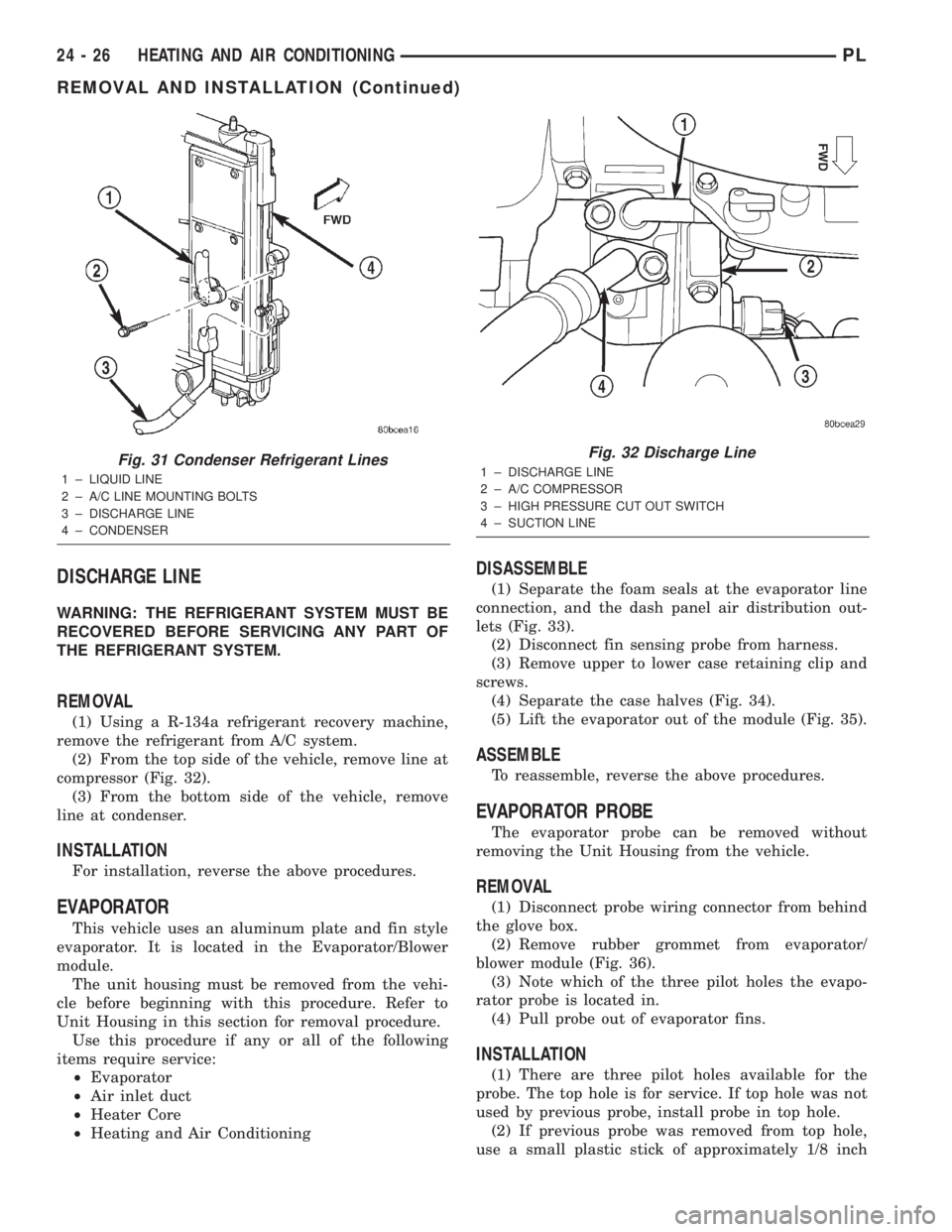
(2) From the top side of the vehicle, remove line at
compressor (Fig. 32).
(3) From the bottom side of the vehicle, remove
line at condenser.
INSTALLATION
For installation, reverse the above procedures.
EVAPORATOR
This vehicle uses an aluminum plate and fin style
evaporator. It is located in the Evaporator/Blower
module.
The unit housing must be removed from the vehi-
cle before beginning with this procedure. Refer to
Unit Housing in this section for removal procedure.
Use this procedure if any or all of the following
items require service:
²Evaporator
²Air inlet duct
²Heater Core
²Heating and Air Conditioning
DISASSEMBLE
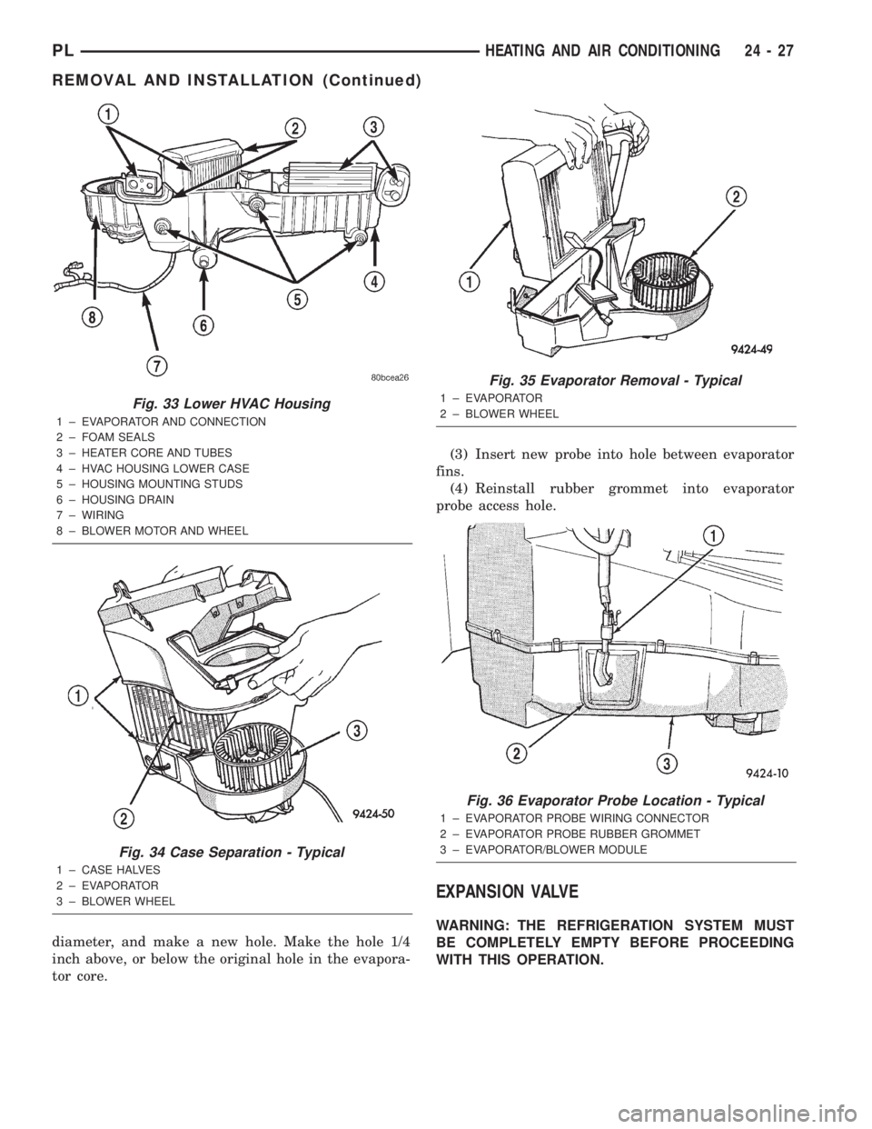
(1) Separate the foam seals at the evaporator line
connection, and the dash panel air distribution out-
lets (Fig. 33).
(2) Disconnect fin sensing probe from harness.
(3) Remove upper to lower case retaining clip and
screws.
(4) Separate the case halves (Fig. 34).
(5) Lift the evaporator out of the module (Fig. 35).
ASSEMBLE
To reassemble, reverse the above procedures.
EVAPORATOR PROBE
The evaporator probe can be removed without
removing the Unit Housing from the vehicle.
REMOVAL
(1) Disconnect probe wiring connector from behind
the glove box.
(2) Remove rubber grommet from evaporator/
blower module (Fig. 36).
(3) Note which of the three pilot holes the evapo-
rator probe is located in.
(4) Pull probe out of evaporator fins.
INSTALLATION
(1) There are three pilot holes available for the
probe. The top hole is for service. If top hole was not
used by previous probe, install probe in top hole.
(2) If previous probe was removed from top hole,
use a small plastic stick of approximately 1/8 inch
Fig. 31 Condenser Refrigerant Lines
1 ± LIQUID LINE
2 ± A/C LINE MOUNTING BOLTS
3 ± DISCHARGE LINE
4 ± CONDENSER
Fig. 32 Discharge Line
1 ± DISCHARGE LINE
2 ± A/C COMPRESSOR
3 ± HIGH PRESSURE CUT OUT SWITCH
4 ± SUCTION LINE
24 - 26 HEATING AND AIR CONDITIONINGPL
REMOVAL AND INSTALLATION (Continued)
Page 1258 of 1285
diameter, and make a new hole. Make the hole 1/4
inch above, or below the original hole in the evapora-
tor core.(3) Insert new probe into hole between evaporator
fins.
(4) Reinstall rubber grommet into evaporator
probe access hole.
EXPANSION VALVE
WARNING: THE REFRIGERATION SYSTEM MUST
BE COMPLETELY EMPTY BEFORE PROCEEDING
WITH THIS OPERATION.
Fig. 33 Lower HVAC Housing
1 ± EVAPORATOR AND CONNECTION
2 ± FOAM SEALS
3 ± HEATER CORE AND TUBES
4 ± HVAC HOUSING LOWER CASE
5 ± HOUSING MOUNTING STUDS
6 ± HOUSING DRAIN
7 ± WIRING
8 ± BLOWER MOTOR AND WHEEL
Fig. 34 Case Separation - Typical
1 ± CASE HALVES
2 ± EVAPORATOR
3 ± BLOWER WHEEL
Fig. 35 Evaporator Removal - Typical
1 ± EVAPORATOR
2 ± BLOWER WHEEL
Fig. 36 Evaporator Probe Location - Typical
1 ± EVAPORATOR PROBE WIRING CONNECTOR
2 ± EVAPORATOR PROBE RUBBER GROMMET
3 ± EVAPORATOR/BLOWER MODULE
PLHEATING AND AIR CONDITIONING 24 - 27
REMOVAL AND INSTALLATION (Continued)
Page 1259 of 1285
REMOVAL
(1) Remove the wire connector from the low pres-
sure cut-off switch.
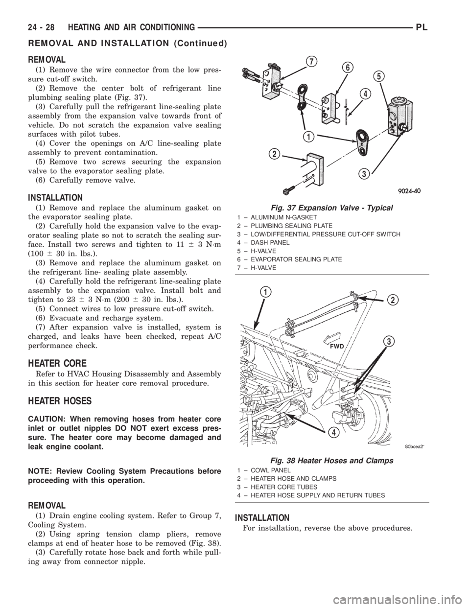
(2) Remove the center bolt of refrigerant line
plumbing sealing plate (Fig. 37).
(3) Carefully pull the refrigerant line-sealing plate
assembly from the expansion valve towards front of
vehicle. Do not scratch the expansion valve sealing
surfaces with pilot tubes.
(4) Cover the openings on A/C line-sealing plate
assembly to prevent contamination.
(5) Remove two screws securing the expansion
valve to the evaporator sealing plate.
(6) Carefully remove valve.
INSTALLATION
(1) Remove and replace the aluminum gasket on
the evaporator sealing plate.
(2) Carefully hold the expansion valve to the evap-
orator sealing plate so not to scratch the sealing sur-
face. Install two screws and tighten to 1163 N´m
(100630 in. lbs.).
(3) Remove and replace the aluminum gasket on
the refrigerant line- sealing plate assembly.
(4) Carefully hold the refrigerant line-sealing plate
assembly to the expansion valve. Install bolt and
tighten to 2363 N´m (200630 in. lbs.).
(5) Connect wires to low pressure cut-off switch.
(6) Evacuate and recharge system.
(7) After expansion valve is installed, system is
charged, and leaks have been checked, repeat A/C
performance check.
HEATER CORE
Refer to HVAC Housing Disassembly and Assembly
in this section for heater core removal procedure.
HEATER HOSES
CAUTION: When removing hoses from heater core
inlet or outlet nipples DO NOT exert excess pres-
sure. The heater core may become damaged and
leak engine coolant.
NOTE: Review Cooling System Precautions before
proceeding with this operation.
REMOVAL
(1) Drain engine cooling system. Refer to Group 7,
Cooling System.
(2) Using spring tension clamp pliers, remove
clamps at end of heater hose to be removed (Fig. 38).
(3) Carefully rotate hose back and forth while pull-
ing away from connector nipple.INSTALLATION
For installation, reverse the above procedures.
Fig. 37 Expansion Valve - Typical
1 ± ALUMINUM N-GASKET
2 ± PLUMBING SEALING PLATE
3 ± LOW/DIFFERENTIAL PRESSURE CUT-OFF SWITCH
4 ± DASH PANEL
5 ± H-VALVE
6 ± EVAPORATOR SEALING PLATE
7 ± H-VALVE
Fig. 38 Heater Hoses and Clamps
1 ± COWL PANEL
2 ± HEATER HOSE AND CLAMPS
3 ± HEATER CORE TUBES
4 ± HEATER HOSE SUPPLY AND RETURN TUBES
24 - 28 HEATING AND AIR CONDITIONINGPL
REMOVAL AND INSTALLATION (Continued)