2000 DODGE NEON weight
[x] Cancel search: weightPage 1071 of 1285
TIRE IDENTIFICATION
Tire type, size, aspect ratio and speed rating are
encoded in the letters and numbers imprinted on the
side wall of the tire. Refer to the chart to decipher
the tire identification code (Fig. 2).
Performance tires will have a speed rating letter
after the aspect ratio number. For example, the letter
ªSº indicates that the tire is speed rated up to 112
mph (180 km/h). The speed rating is not always
printed on the tire sidewall.
²Q -up to 100 mph (160 km/h)
²T -up to 118 mph (190 km/h)
²U -up to 124 mph (200 km/h)
²H -up to 130 mph (210 km/h)
²V -up to 149 mph (240 km/h)
²Z -more than 149 mph (240 km/h) (consult the
tire manufacturer for the specific speed rating)
An All Season type tire will have eitherM+S,M
& S or M-S (indicating mud and snow traction)
imprinted on the side wall.
TIRE CHAINS
Refer to the owners manual supplied with the vehi-
cle to determine whether the use of tire chains is per-
mitted on this vehicle.
RADIAL-PLY TIRES
Radial-ply tires improve handling, tread life and
ride quality, and decrease rolling resistance.
Radial-ply tires must always be used in sets of
four. Under no circumstances should they be used on
the front only. They may be mixed with temporary
spare tires when necessary. A maximum speed of 50
MPH is recommended while a temporary spare is in
use.
Radial-ply tires have the same load-carrying capac-
ity as other types of tires of the same size. They also
use the same recommended inflation pressures.
The use of oversized tires, either in the front or
rear of the vehicle, can cause vehicle drive train fail-
ure. This could also cause inaccurate wheel speed
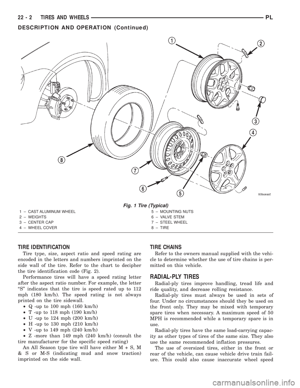
Fig. 1 Tire (Typical)
1 ± CAST ALUMINUM WHEEL
2 ± WEIGHTS
3 ± CENTER CAP
4 ± WHEEL COVER5 ± MOUNTING NUTS
6 ± VALVE STEM
7 ± STEEL WHEEL
8 ± TIRE
22 - 2 TIRES AND WHEELSPL
DESCRIPTION AND OPERATION (Continued)
Page 1079 of 1285
WHEELS
TABLE OF CONTENTS
page page
DESCRIPTION AND OPERATION
WHEEL................................10
WHEEL COVER (LOCK-ON).................11
DIAGNOSIS AND TESTING
WHEEL INSPECTION......................11
TIRE AND WHEEL RUNOUT................12
SERVICE PROCEDURES
TIRE AND WHEEL BALANCE................13REMOVAL AND INSTALLATION
WHEEL COVER (LOCK-ON).................15
WHEEL COVER RETAINING NUT............15
TIRE AND WHEEL ASSEMBLY...............16
SPECIFICATIONS
WHEEL SPECIFICATIONS..................17
DESCRIPTION AND OPERATION
WHEEL
Original equipment wheels are designed for proper
operation at all loads up to the specified maximum
vehicle capacity.All models use steel or cast aluminum drop center
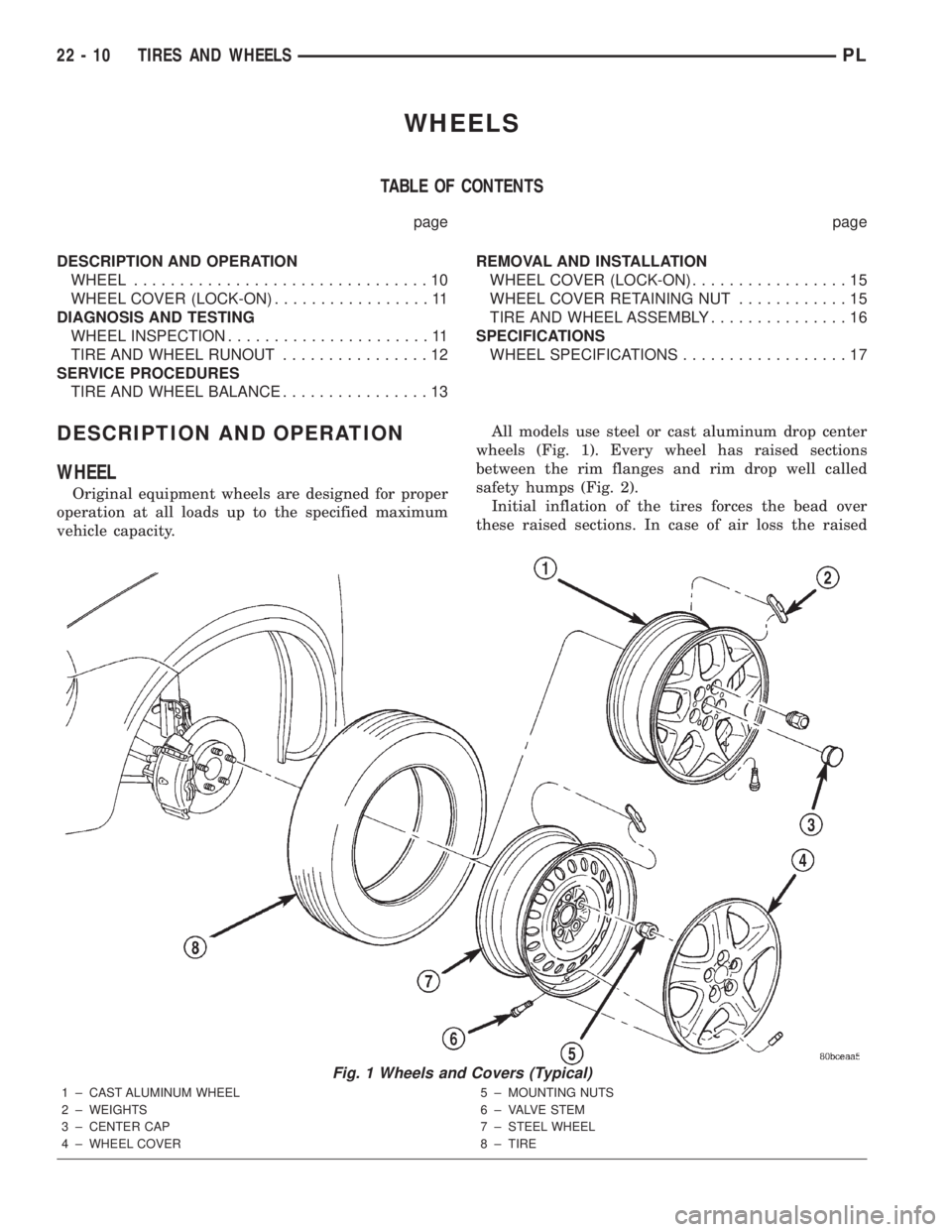
wheels (Fig. 1). Every wheel has raised sections
between the rim flanges and rim drop well called
safety humps (Fig. 2).
Initial inflation of the tires forces the bead over
these raised sections. In case of air loss the raised
Fig. 1 Wheels and Covers (Typical)
1 ± CAST ALUMINUM WHEEL
2 ± WEIGHTS
3 ± CENTER CAP
4 ± WHEEL COVER5 ± MOUNTING NUTS
6 ± VALVE STEM
7 ± STEEL WHEEL
8 ± TIRE
22 - 10 TIRES AND WHEELSPL
Page 1080 of 1285
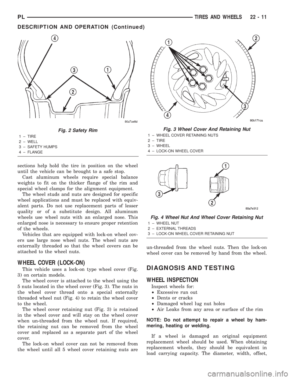
sections help hold the tire in position on the wheel
until the vehicle can be brought to a safe stop.
Cast aluminum wheels require special balance
weights to fit on the thicker flange of the rim and
special wheel clamps for the alignment equipment.
The wheel studs and nuts are designed for specific
wheel applications and must be replaced with equiv-
alent parts. Do not use replacement parts of lesser
quality or of a substitute design. All aluminum
wheels use wheel nuts with an enlarged nose. This
enlarged nose is necessary to ensure proper retention
of the wheels.
Vehicles that are equipped with lock-on wheel cov-
ers use large nose wheel nuts. The wheel nuts are
externally threaded so that the wheel covers can be
attached to the wheel nuts.
WHEEL COVER (LOCK-ON)
This vehicle uses a lock-on type wheel cover (Fig.
3) on certain models.
The wheel cover is attached to the wheel using the
5 nuts located in the wheel cover (Fig. 3). The nuts in
the wheel cover thread onto a special externally
threaded wheel nut (Fig. 4) to retain the wheel cover
to the wheel.
The wheel cover retaining nut (Fig. 3) is retained
in the wheel cover and will stay on the wheel cover
when un-threaded from the wheel nut. If required,
the retaining nut can be removed from the wheel
cover and replaced as a separate part of the wheel
cover.
The lock-on wheel cover can not be removed from
the wheel until all 5 wheel cover retaining nuts areun-threaded from the wheel nuts. Then the lock-on
wheel cover can be removed by hand from the wheel.DIAGNOSIS AND TESTING
WHEEL INSPECTION
Inspect wheels for:
²Excessive run out
²Dents or cracks
²Damaged wheel lug nut holes
²Air Leaks from any area or surface of the rim
NOTE: Do not attempt to repair a wheel by ham-
mering, heating or welding.
If a wheel is damaged an original equipment
replacement wheel should be used. When obtaining
replacement wheels, they should be equivalent in
load carrying capacity. The diameter, width, offset,
Fig. 2 Safety Rim
1 ± TIRE
2 ± WELL
3 ± SAFETY HUMPS
4 ± FLANGE
Fig. 3 Wheel Cover And Retaining Nut
1 ± WHEEL COVER RETAINING NUTS
2 ± TIRE
3 ± WHEEL
4 ± LOCK-ON WHEEL COVER
Fig. 4 Wheel Nut And Wheel Cover Retaining Nut
1 ± WHEEL NUT
2 ± EXTERNAL THREADS
3 ± LOCK-ON WHEEL COVER RETAINING NUT
PLTIRES AND WHEELS 22 - 11
DESCRIPTION AND OPERATION (Continued)
Page 1082 of 1285
METHOD 2 (RELOCATE TIRE ON WHEEL)
Rotating tire on wheel is particularly effective
when there is run out in both tire and wheel.
Remove tire from wheel and remount wheel on hub
in former position.
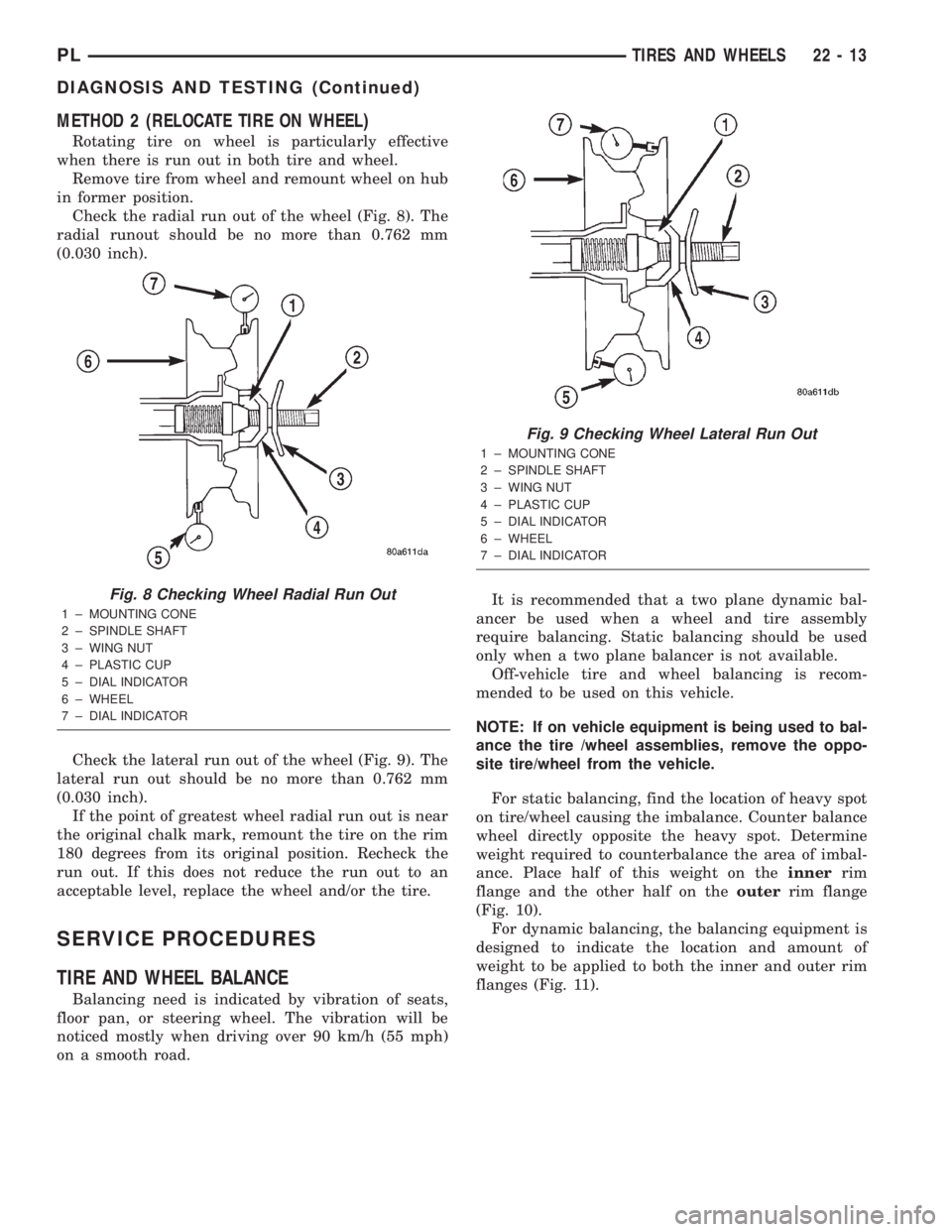
Check the radial run out of the wheel (Fig. 8). The
radial runout should be no more than 0.762 mm
(0.030 inch).
Check the lateral run out of the wheel (Fig. 9). The
lateral run out should be no more than 0.762 mm
(0.030 inch).
If the point of greatest wheel radial run out is near
the original chalk mark, remount the tire on the rim
180 degrees from its original position. Recheck the
run out. If this does not reduce the run out to an
acceptable level, replace the wheel and/or the tire.
SERVICE PROCEDURES
TIRE AND WHEEL BALANCE
Balancing need is indicated by vibration of seats,
floor pan, or steering wheel. The vibration will be
noticed mostly when driving over 90 km/h (55 mph)
on a smooth road.It is recommended that a two plane dynamic bal-
ancer be used when a wheel and tire assembly
require balancing. Static balancing should be used
only when a two plane balancer is not available.
Off-vehicle tire and wheel balancing is recom-
mended to be used on this vehicle.
NOTE: If on vehicle equipment is being used to bal-
ance the tire /wheel assemblies, remove the oppo-
site tire/wheel from the vehicle.
For static balancing, find the location of heavy spot
on tire/wheel causing the imbalance. Counter balance
wheel directly opposite the heavy spot. Determine
weight required to counterbalance the area of imbal-
ance. Place half of this weight on theinnerrim
flange and the other half on theouterrim flange
(Fig. 10).
For dynamic balancing, the balancing equipment is
designed to indicate the location and amount of
weight to be applied to both the inner and outer rim
flanges (Fig. 11).
Fig. 8 Checking Wheel Radial Run Out
1 ± MOUNTING CONE
2 ± SPINDLE SHAFT
3 ± WING NUT
4 ± PLASTIC CUP
5 ± DIAL INDICATOR
6 ± WHEEL
7 ± DIAL INDICATOR
Fig. 9 Checking Wheel Lateral Run Out
1 ± MOUNTING CONE
2 ± SPINDLE SHAFT
3 ± WING NUT
4 ± PLASTIC CUP
5 ± DIAL INDICATOR
6 ± WHEEL
7 ± DIAL INDICATOR
PLTIRES AND WHEELS 22 - 13
DIAGNOSIS AND TESTING (Continued)
Page 1083 of 1285
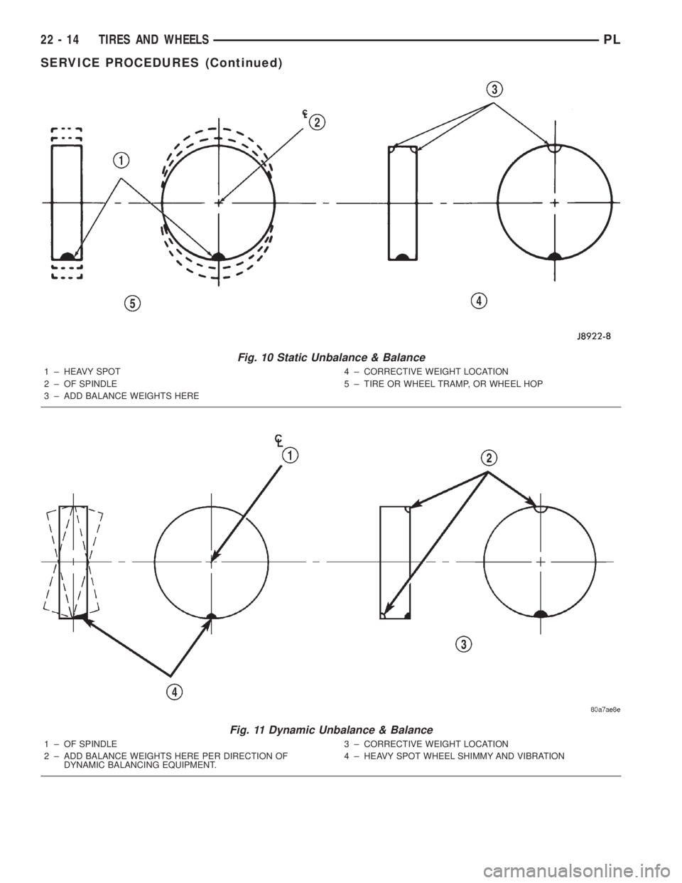
Fig. 10 Static Unbalance & Balance
1 ± HEAVY SPOT
2 ± OF SPINDLE
3 ± ADD BALANCE WEIGHTS HERE4 ± CORRECTIVE WEIGHT LOCATION
5 ± TIRE OR WHEEL TRAMP, OR WHEEL HOP
Fig. 11 Dynamic Unbalance & Balance
1 ± OF SPINDLE
2 ± ADD BALANCE WEIGHTS HERE PER DIRECTION OF
DYNAMIC BALANCING EQUIPMENT.3 ± CORRECTIVE WEIGHT LOCATION
4 ± HEAVY SPOT WHEEL SHIMMY AND VIBRATION
22 - 14 TIRES AND WHEELSPL
SERVICE PROCEDURES (Continued)
Page 1275 of 1285
VIN CODE DECODING
POSITION INTERPRETATION CODE = DESCRIPTION
1 Country of Origin 1 = United states
2 MakeB = Dodge
P = Plymouth
3 Vehicle Type 3 = Passenger Car
4 Pass. Safety E = Restraint System, Active Driver & Passenger Airbags
5 Car Line S = Neon
6 Series2 = Low Line
4 = High Line
7 Body Style6 = 4 Door Sedan
8 Engine C = 2.0 L 4 Cyl. 16V
9 Check Digit See explanation in this section.
10 Model Year Y = 2000
11 Assembly Plant D = Belvidere
12 Thru 17 Vehicle Build Sequence 6 digit number assigned by assembly plant.
VEHICLE SAFETY CERTIFICATION LABEL
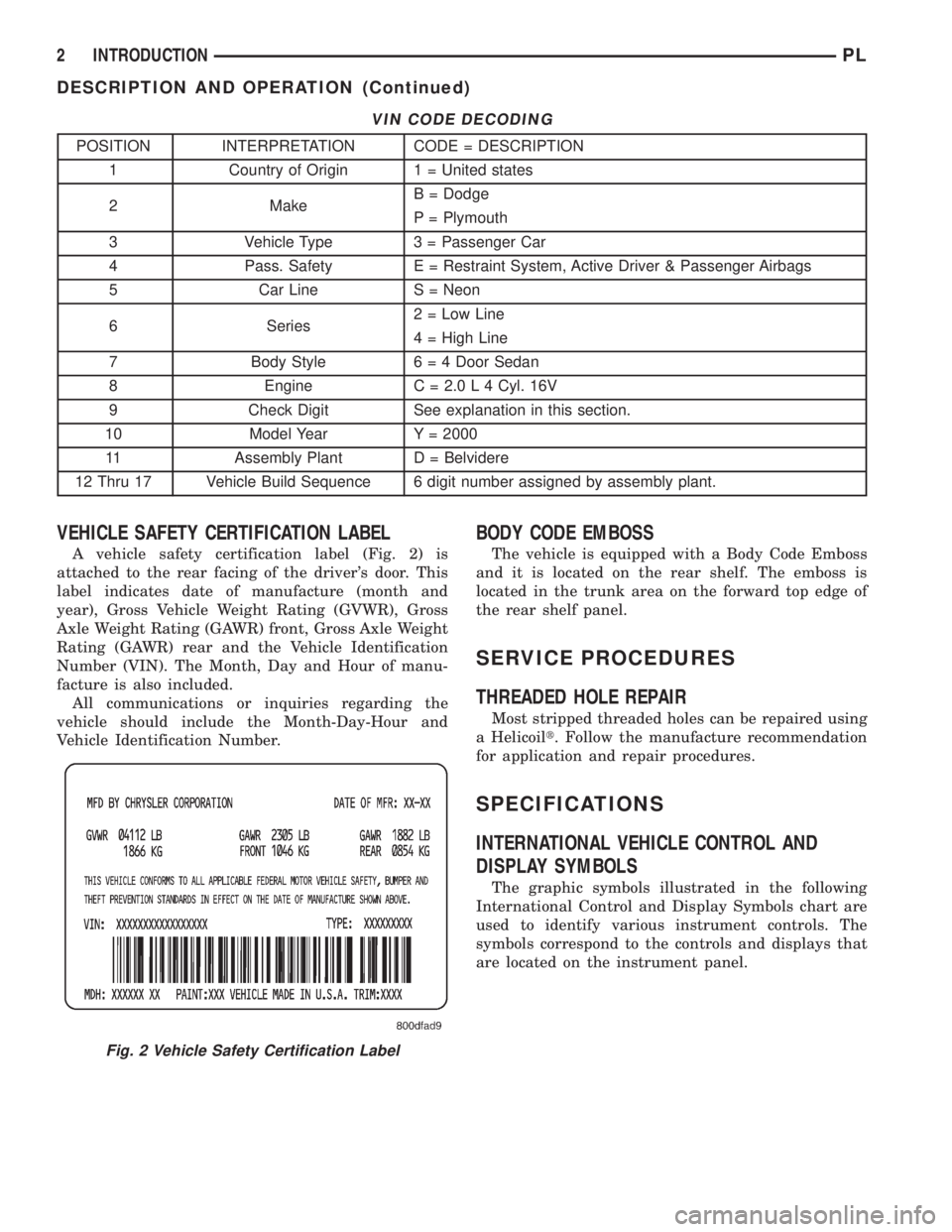
A vehicle safety certification label (Fig. 2) is
attached to the rear facing of the driver's door. This
label indicates date of manufacture (month and
year), Gross Vehicle Weight Rating (GVWR), Gross
Axle Weight Rating (GAWR) front, Gross Axle Weight
Rating (GAWR) rear and the Vehicle Identification
Number (VIN). The Month, Day and Hour of manu-
facture is also included.
All communications or inquiries regarding the
vehicle should include the Month-Day-Hour and
Vehicle Identification Number.
BODY CODE EMBOSS
The vehicle is equipped with a Body Code Emboss
and it is located on the rear shelf. The emboss is
located in the trunk area on the forward top edge of
the rear shelf panel.
SERVICE PROCEDURES
THREADED HOLE REPAIR
Most stripped threaded holes can be repaired using
a Helicoilt. Follow the manufacture recommendation
for application and repair procedures.
SPECIFICATIONS
INTERNATIONAL VEHICLE CONTROL AND
DISPLAY SYMBOLS
The graphic symbols illustrated in the following
International Control and Display Symbols chart are
used to identify various instrument controls. The
symbols correspond to the controls and displays that
are located on the instrument panel.
Fig. 2 Vehicle Safety Certification Label
2 INTRODUCTIONPL
DESCRIPTION AND OPERATION (Continued)