2000 DODGE NEON weight
[x] Cancel search: weightPage 738 of 1285
2.0L SOHC ENGINE
TABLE OF CONTENTS
page page
DESCRIPTION AND OPERATION
ENGINE IDENTIFICATION..................15
ENGINE COMPONENTS...................15
ENGINE LUBRICATION SYSTEM.............17
DIAGNOSIS AND TESTING
CHECKING ENGINE OIL PRESSURE..........18
SERVICE PROCEDURES
CYLINDER BORE AND PISTON SIZING........18
FITTING PISTON RINGS...................19
FITTING CONNECTING RODS...............19
FITTING CRANKSHAFT BEARINGS...........19
CRANKSHAFT END PLAY..................20
REMOVAL AND INSTALLATION
TORQUE STRUTS........................20
ENGINE MOUNTÐLEFT...................21
ENGINE MOUNTÐRIGHT..................23
ENGINE MOUNT BRACKETÐRIGHT..........24
STRUCTURAL COLLAR....................25
ENGINE ASSEMBLY.......................25
INTAKE MANIFOLD.......................28
EXHAUST MANIFOLD.....................30
CYLINDER HEAD COVER..................31
SPARK PLUG TUBE SEALS.................32
SPARK PLUG TUBE.......................33
CAMSHAFT.............................33
ROCKER ARM/HYDRAULIC LASH ADJUSTER . . . 34
VALVE SEALS AND SPRINGSÐIN VEHICLE....36
CYLINDER HEAD.........................37
CRANKSHAFT DAMPER...................40
TIMING BELT COVERS....................41TIMING BELT............................43
TIMING BELT TENSIONER..................46
CAMSHAFT OIL SEAL.....................46
OILPAN................................47
CRANKSHAFT OIL SEALÐFRONT............48
CRANKSHAFT OIL SEALÐREAR.............50
DRIVE PLATE...........................51
CRANKSHAFT...........................52
OIL FILTER ADAPTER.....................55
OILFILTER .............................55
OIL PUMP..............................55
PISTON AND CONNECTING ROD............57
DISASSEMBLY AND ASSEMBLY
OIL PUMP..............................60
VALVE SERVICE WITH THE CYLINDER HEAD
REMOVED............................60
CLEANING AND INSPECTION
INTAKE MANIFOLD.......................63
EXHAUST MANIFOLD.....................63
CYLINDER HEAD AND CAMSHAFT
JOURNALS............................63
OIL PUMP..............................64
CYLINDER BLOCK AND BORE..............65
ADJUSTMENTS
ENGINE TORQUE STRUT ADJUSTMENT......66
SPECIFICATIONS
2.0L SOHC ENGINE.......................68
TORQUE...............................71
SPECIAL TOOLS
2.0L SOHC ENGINE.......................72
DESCRIPTION AND OPERATION
ENGINE IDENTIFICATION
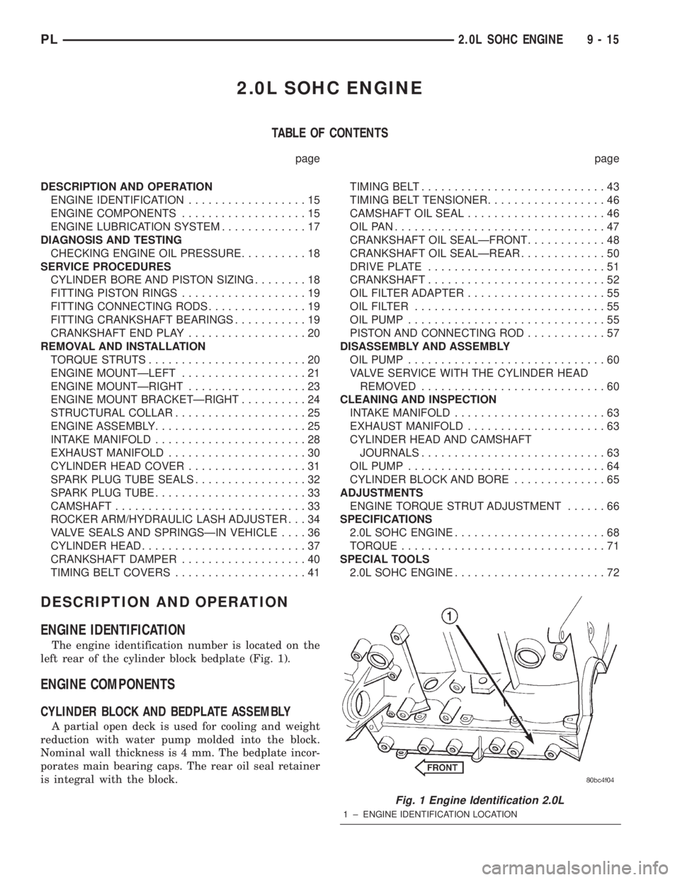
The engine identification number is located on the
left rear of the cylinder block bedplate (Fig. 1).
ENGINE COMPONENTS
CYLINDER BLOCK AND BEDPLATE ASSEMBLY
A partial open deck is used for cooling and weight
reduction with water pump molded into the block.
Nominal wall thickness is 4 mm. The bedplate incor-
porates main bearing caps. The rear oil seal retainer
is integral with the block.
Fig. 1 Engine Identification 2.0L
1 ± ENGINE IDENTIFICATION LOCATION
PL2.0L SOHC ENGINE 9 - 15
Page 739 of 1285
CRANKSHAFT
A nodular cast iron crankshaft is used. The engine
has five main bearings. The number three main is
flanged to control thrust. The mains and connecting
rod journals have undercut fillet radiuses that are
deep rolled for added strength. To optimize bearing
loading, eight counterweights are used. Hydrody-
namic seals provide end sealing, where the crank-
shaft exits the block. Anaerobic gasket material is
used for parting line sealing. A sintered iron timing
belt sprocket is mounted on the crankshaft nose. This
sprocket transmits crankshaft movement, via timing
belt to the camshaft sprocket providing timed valve
actuation.
PISTONS
The engineDOES NOThave provision for a free
wheeling valve train. Non free wheeling valve train
means, in the event of a broken timing belt pistons
will contact the valves. The engine uses pressed-in
piston pins to attach forged powdered metal connect-
ing rods. The connecting rods are a cracked cap
design and are not repairable. Hex head cap screw
are used to provide alignment and durability in the
assembly. Pistons and connecting rods are serviced as
an assembly.
PISTON RINGS
The piston rings include a molybdenum faced top
ring for reliable compression sealing and a taper
faced intermediate ring for additional cylinder pres-
sure control. Oil Control Ring Package consist of two
steel rails and an expander spacer.
CYLINDER HEAD
The aluminum cylinder head features a Single
Over Head Camshaft (SOHC), four-valves per cylin-
der, cross flow design. The valves are arranged in
two inline banks, with the two intake per cylinder
facing toward the radiator. The exhaust valves facing
toward the dash panel. Rocker arm shafts mount
directly to the cylinder head. It incorporates powder
metal valve guides and seats. The hollow rocker arm
shafts supplies oil to the hydraulic lash adjusters,
camshaft and valve mechanisms.
CAMSHAFT
The nodular iron camshaft has five bearing jour-
nals and three cam lobes per cylinder. Provision for a
cam position sensor is provided on the camshaft at
the rear of cylinder head which also acts as thrust
plate. A hydrodynamic oil seal is used for oil control
at the front of the camshaft.
VALVES
Four valves per cylinder are actuated by roller
rocker arms/hydraulic lash adjusters assemblies
which pivot on rocker arm shafts. All valves have
chrome plated valve stems. Viton rubber valve stem
seals are integral with spring seats. Valve springs,
spring retainers, and locks are conventional design.
INTAKE MANIFOLD
The intake manifold is a molded plastic composi-
tion, attached to the cylinder head with five fasten-
ers. This long branch design enhances low and mid-
range torque.
EXHAUST MANIFOLD
The exhaust manifold is made of nodular cast iron
for strength and high temperatures. Exhaust gasses
exit the manifold into an articulated joint connection
and exhaust pipe.
COMPONENT REPLACEMENT
If any of the following parts have been changed or
replaced:
²Camshaft
²Camshaft Position Sensor
²Camshaft Position Sensor Target Magnet
²Cylinder Block
²Cylinder Head
²Water Pump
²Powertrain Control Module (PCM)
²Timing Belt and Timing Belt Tensioner
The camshaft and crankshaft timing relearn proce-
dure must be performed. Refer to the component
Removal and Installation procedure in this section.
9 - 16 2.0L SOHC ENGINEPL
DESCRIPTION AND OPERATION (Continued)
Page 749 of 1285
(4) Discharge air conditioning system, if equipped.
Refer to Group 24, Heating and Air Conditioning for
procedure.
(5) Disconnect the following: air intake duct at
intake manifold, throttle cables, electrical connectors
from throttle body and air cleaner housing.
(6) Remove air cleaner housing assembly.
(7) Remove upper radiator hose and fan module.
Refer to Group 7, Cooling System for procedure.
(8) Remove lower radiator hose.
(9) Disconnect automatic transmission cooler lines
and plug, if equipped.
(10) Disconnect shift linkage, electrical connectors,
and clutch cable, if equipped with manual transaxle.
(11) Disconnect engine wiring harness.
(12) Disconnect positive cable from Power Distri-
bution Center (PDC) and ground wire from vehicle
body.
(13) Disconnect ground wire from the vehicle body-
to-engine at the right side strut tower.
(14) Disconnect heater hoses.
(15) Disconnect vacuum hose from brake booster.
(16) Disconnect coolant reserve/recovery hose.
(17) Remove accessory drive belts. Refer to Group
7, Cooling System for procedure.
(18) Remove power steering pump and reservoir
and set them aside.
(19) Hoist vehicle and remove right inner splash
shield.
(20) Drain engine oil.
(21) Remove front wheels.
(22) Remove axle shafts. Refer to Group 3, Differ-
ential and Driveline for procedure.
(23) Disconnect exhaust system from manifold.
(24) Disconnect the downstream oxygen sensor
connector.
(25) Remove lower engine torque strut.
(26) Remove structural collar. Refer to procedure
in this section.
(27) Lower vehicle and remove A/C compressor.
(28) Raise vehicle enough to allow engine dolly
and cradle, Special Tools 6135 and 6710 to be
installed under vehicle.
(29) Loosen engine support posts to allow move-
ment for positioning onto engine locating holes and
flange on the engine bedplate. Lower vehicle and
position cradle until the engine is resting on support
posts (Fig. 26). Tighten mounts to cradle frame. This
will keep support posts from moving when removing
or installing engine and transmission.
(30) Install safety straps around the engine to cra-
dle (Fig. 26). Tighten straps and lock them into posi-
tion.
WARNING: Safety straps MUST be used.(31) Raise vehicle enough to see if straps are tight
enough to hold cradle assembly to engine.
(32) Lower vehicle so weight of the engine and
transmission ONLY is on the cradle assembly.
(33) Remove the upper engine torque strut.
(34) Remove right and left engine and transaxle
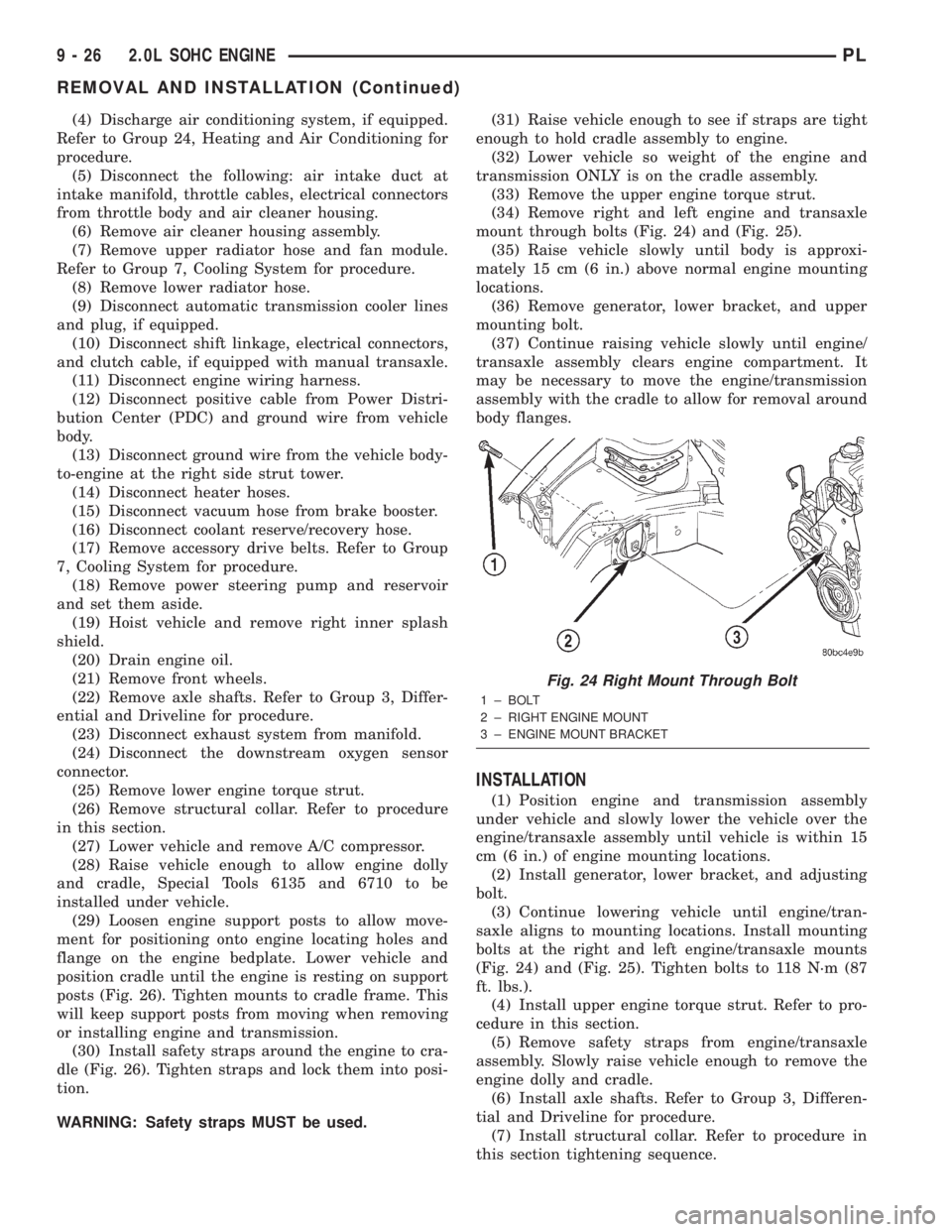
mount through bolts (Fig. 24) and (Fig. 25).
(35) Raise vehicle slowly until body is approxi-
mately 15 cm (6 in.) above normal engine mounting
locations.
(36) Remove generator, lower bracket, and upper
mounting bolt.
(37) Continue raising vehicle slowly until engine/
transaxle assembly clears engine compartment. It
may be necessary to move the engine/transmission
assembly with the cradle to allow for removal around
body flanges.
INSTALLATION
(1) Position engine and transmission assembly
under vehicle and slowly lower the vehicle over the
engine/transaxle assembly until vehicle is within 15
cm (6 in.) of engine mounting locations.
(2) Install generator, lower bracket, and adjusting
bolt.
(3) Continue lowering vehicle until engine/tran-
saxle aligns to mounting locations. Install mounting
bolts at the right and left engine/transaxle mounts
(Fig. 24) and (Fig. 25). Tighten bolts to 118 N´m (87
ft. lbs.).
(4) Install upper engine torque strut. Refer to pro-
cedure in this section.
(5) Remove safety straps from engine/transaxle
assembly. Slowly raise vehicle enough to remove the
engine dolly and cradle.
(6) Install axle shafts. Refer to Group 3, Differen-
tial and Driveline for procedure.
(7) Install structural collar. Refer to procedure in
this section tightening sequence.
Fig. 24 Right Mount Through Bolt
1 ± BOLT
2 ± RIGHT ENGINE MOUNT
3 ± ENGINE MOUNT BRACKET
9 - 26 2.0L SOHC ENGINEPL
REMOVAL AND INSTALLATION (Continued)
Page 764 of 1285
(2) Install crankshaft damper bolt. Using Special
Tool 6847 and a torque wrench, tighten bolt to 136
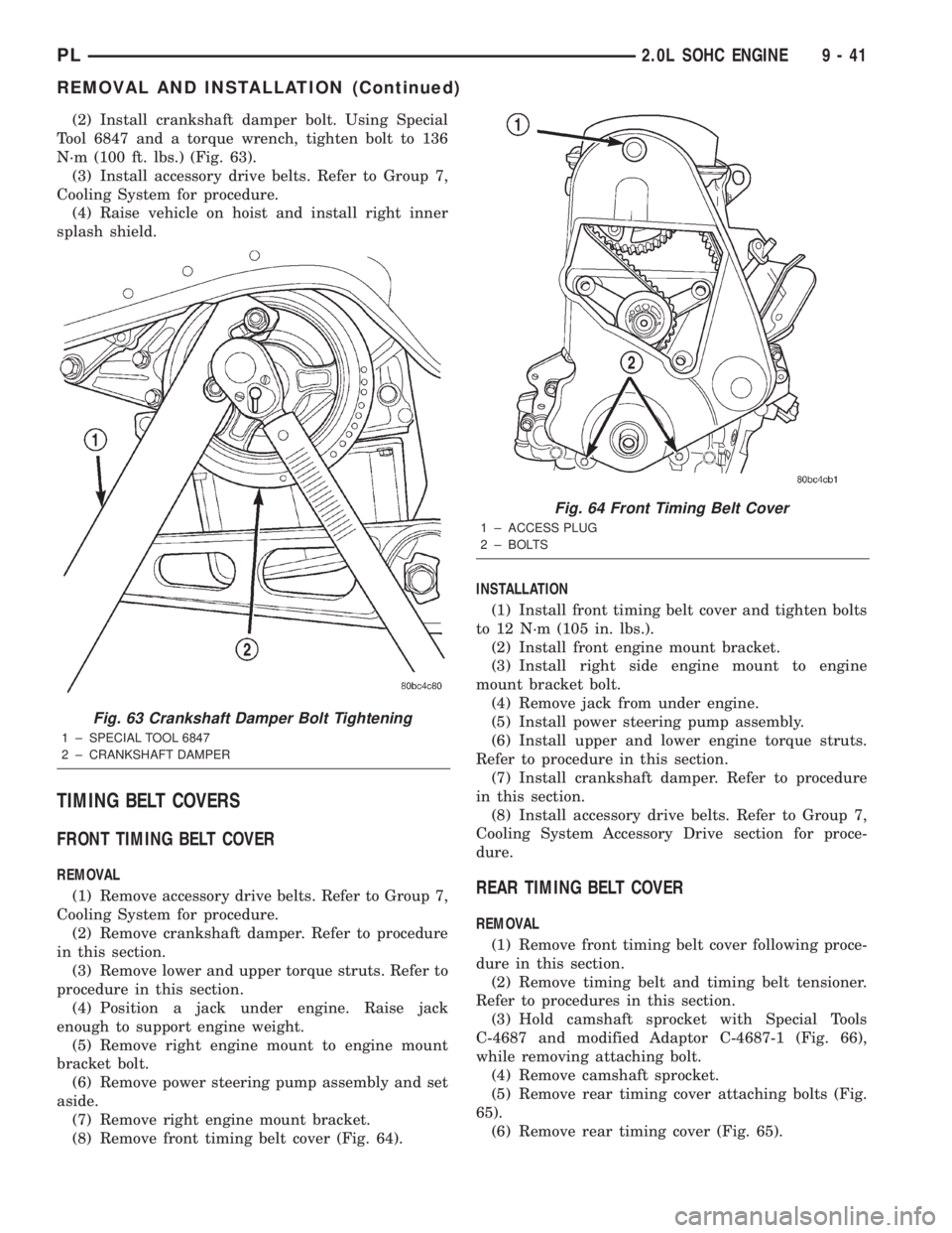
N´m (100 ft. lbs.) (Fig. 63).
(3) Install accessory drive belts. Refer to Group 7,
Cooling System for procedure.
(4) Raise vehicle on hoist and install right inner
splash shield.
TIMING BELT COVERS
FRONT TIMING BELT COVER
REMOVAL
(1) Remove accessory drive belts. Refer to Group 7,
Cooling System for procedure.
(2) Remove crankshaft damper. Refer to procedure
in this section.
(3) Remove lower and upper torque struts. Refer to
procedure in this section.
(4) Position a jack under engine. Raise jack
enough to support engine weight.
(5) Remove right engine mount to engine mount
bracket bolt.
(6) Remove power steering pump assembly and set
aside.
(7) Remove right engine mount bracket.
(8) Remove front timing belt cover (Fig. 64).INSTALLATION
(1) Install front timing belt cover and tighten bolts
to 12 N´m (105 in. lbs.).
(2) Install front engine mount bracket.
(3) Install right side engine mount to engine
mount bracket bolt.
(4) Remove jack from under engine.
(5) Install power steering pump assembly.
(6) Install upper and lower engine torque struts.
Refer to procedure in this section.
(7) Install crankshaft damper. Refer to procedure
in this section.
(8) Install accessory drive belts. Refer to Group 7,
Cooling System Accessory Drive section for proce-
dure.REAR TIMING BELT COVER
REMOVAL
(1) Remove front timing belt cover following proce-
dure in this section.
(2) Remove timing belt and timing belt tensioner.
Refer to procedures in this section.
(3) Hold camshaft sprocket with Special Tools
C-4687 and modified Adaptor C-4687-1 (Fig. 66),
while removing attaching bolt.
(4) Remove camshaft sprocket.
(5) Remove rear timing cover attaching bolts (Fig.
65).
(6) Remove rear timing cover (Fig. 65).
Fig. 63 Crankshaft Damper Bolt Tightening
1 ± SPECIAL TOOL 6847
2 ± CRANKSHAFT DAMPER
Fig. 64 Front Timing Belt Cover
1 ± ACCESS PLUG
2 ± BOLTS
PL2.0L SOHC ENGINE 9 - 41
REMOVAL AND INSTALLATION (Continued)
Page 780 of 1285
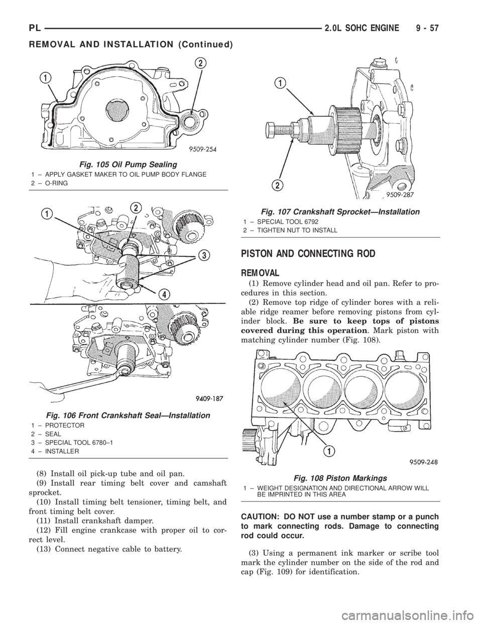
(8) Install oil pick-up tube and oil pan.
(9) Install rear timing belt cover and camshaft
sprocket.
(10) Install timing belt tensioner, timing belt, and
front timing belt cover.
(11) Install crankshaft damper.
(12) Fill engine crankcase with proper oil to cor-
rect level.
(13) Connect negative cable to battery.
PISTON AND CONNECTING ROD
REMOVAL
(1) Remove cylinder head and oil pan. Refer to pro-
cedures in this section.
(2) Remove top ridge of cylinder bores with a reli-
able ridge reamer before removing pistons from cyl-
inder block.Be sure to keep tops of pistons
covered during this operation. Mark piston with
matching cylinder number (Fig. 108).
CAUTION: DO NOT use a number stamp or a punch
to mark connecting rods. Damage to connecting
rod could occur.
(3) Using a permanent ink marker or scribe tool
mark the cylinder number on the side of the rod and
cap (Fig. 109) for identification.
Fig. 105 Oil Pump Sealing
1 ± APPLY GASKET MAKER TO OIL PUMP BODY FLANGE
2 ± O-RING
Fig. 106 Front Crankshaft SealÐInstallation
1 ± PROTECTOR
2 ± SEAL
3 ± SPECIAL TOOL 6780±1
4 ± INSTALLER
Fig. 107 Crankshaft SprocketÐInstallation
1 ± SPECIAL TOOL 6792
2 ± TIGHTEN NUT TO INSTALL
Fig. 108 Piston Markings
1 ± WEIGHT DESIGNATION AND DIRECTIONAL ARROW WILL
BE IMPRINTED IN THIS AREA
PL2.0L SOHC ENGINE 9 - 57
REMOVAL AND INSTALLATION (Continued)
Page 781 of 1285
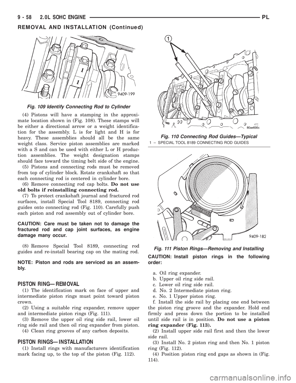
(4) Pistons will have a stamping in the approxi-
mate location shown in (Fig. 108). These stamps will
be either a directional arrow or a weight identifica-
tion for the assembly. L is for light and H is for
heavy. These assemblies should all be the same
weight class. Service piston assemblies are marked
with a S and can be used with either L or H produc-
tion assemblies. The weight designation stamps
should face toward the timing belt side of the engine.
(5) Pistons and connecting rods must be removed
from top of cylinder block. Rotate crankshaft so that
each connecting rod is centered in cylinder bore.
(6) Remove connecting rod cap bolts.Do not use
old bolts if reinstalling connecting rod.
(7) To protect crankshaft journal and fractured rod
surfaces, install Special Tool 8189, connecting rod
guides onto connecting rod (Fig. 110). Carefully push
each piston and rod assembly out of cylinder bore.
CAUTION: Care must be taken not to damage the
fractured rod and cap joint surfaces, as engine
damage many occur.
(8) Remove Special Tool 8189, connecting rod
guides and re-install bearing cap on the mating rod.
NOTE: Piston and rods are serviced as an assem-
bly.
PISTON RINGÐREMOVAL
(1) The identification mark on face of upper and
intermediate piston rings must point toward piston
crown.
(2) Using a suitable ring expander, remove upper
and intermediate piston rings (Fig. 111).
(3) Remove the upper oil ring side rail, lower oil
ring side rail and then oil ring expander from piston.
(4) Clean ring grooves of any carbon deposits.
PISTON RINGSÐINSTALLATION
(1) Install rings with manufacturers identification
mark facing up, to the top of the piston (Fig. 112).CAUTION: Install piston rings in the following
order:
a. Oil ring expander.
b. Upper oil ring side rail.
c. Lower oil ring side rail.
d. No. 2 Intermediate piston ring.
e. No. 1 Upper piston ring.
f. Install the side rail by placing one end between
the piston ring groove and the expander. Hold end
firmly and press down the portion to be installed
until side rail is in position.Do not use a piston
ring expander (Fig. 113).
(2) Install upper side rail first and then the lower
side rail.
(3) Install No. 2 piston ring and then No. 1 piston
ring (Fig. 112).
(4) Position piston ring end gaps as shown in (Fig.
114).
Fig. 109 Identify Connecting Rod to Cylinder
Fig. 110 Connecting Rod GuidesÐTypical
1 ± SPECIAL TOOL 8189 CONNECTING ROD GUIDES
Fig. 111 Piston RingsÐRemoving and Installing
9 - 58 2.0L SOHC ENGINEPL
REMOVAL AND INSTALLATION (Continued)
Page 782 of 1285
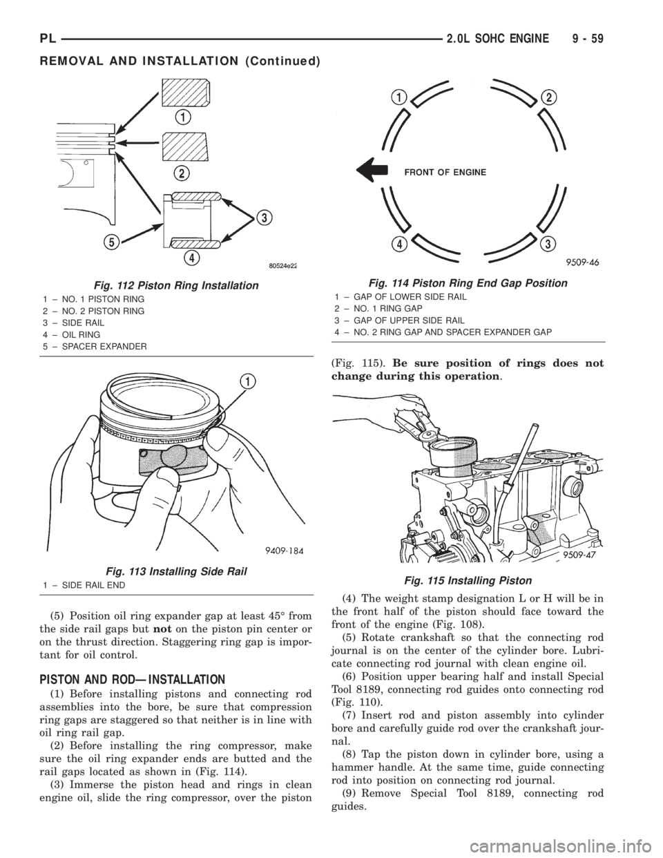
(5) Position oil ring expander gap at least 45É from
the side rail gaps butnoton the piston pin center or
on the thrust direction. Staggering ring gap is impor-
tant for oil control.
PISTON AND RODÐINSTALLATION
(1) Before installing pistons and connecting rod
assemblies into the bore, be sure that compression
ring gaps are staggered so that neither is in line with
oil ring rail gap.
(2) Before installing the ring compressor, make
sure the oil ring expander ends are butted and the
rail gaps located as shown in (Fig. 114).
(3) Immerse the piston head and rings in clean
engine oil, slide the ring compressor, over the piston(Fig. 115).Be sure position of rings does not
change during this operation.
(4) The weight stamp designation L or H will be in
the front half of the piston should face toward the
front of the engine (Fig. 108).
(5) Rotate crankshaft so that the connecting rod
journal is on the center of the cylinder bore. Lubri-
cate connecting rod journal with clean engine oil.
(6) Position upper bearing half and install Special
Tool 8189, connecting rod guides onto connecting rod
(Fig. 110).
(7) Insert rod and piston assembly into cylinder
bore and carefully guide rod over the crankshaft jour-
nal.
(8) Tap the piston down in cylinder bore, using a
hammer handle. At the same time, guide connecting
rod into position on connecting rod journal.
(9) Remove Special Tool 8189, connecting rod
guides.
Fig. 112 Piston Ring Installation
1 ± NO. 1 PISTON RING
2 ± NO. 2 PISTON RING
3 ± SIDE RAIL
4 ± OIL RING
5 ± SPACER EXPANDER
Fig. 113 Installing Side Rail
1 ± SIDE RAIL END
Fig. 114 Piston Ring End Gap Position
1 ± GAP OF LOWER SIDE RAIL
2 ± NO. 1 RING GAP
3 ± GAP OF UPPER SIDE RAIL
4 ± NO. 2 RING GAP AND SPACER EXPANDER GAP
Fig. 115 Installing Piston
PL2.0L SOHC ENGINE 9 - 59
REMOVAL AND INSTALLATION (Continued)
Page 791 of 1285
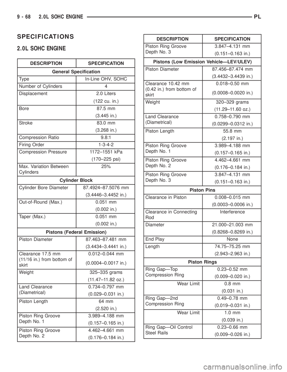
SPECIFICATIONS
2.0L SOHC ENGINE
DESCRIPTION SPECIFICATION
General Specification
Type In-Line OHV, SOHC
Number of Cylinders 4
Displacement 2.0 Liters
(122 cu. in.)
Bore 87.5 mm
(3.445 in.)
Stroke 83.0 mm
(3.268 in.)
Compression Ratio 9.8:1
Firing Order 1-3-4-2
Compression Pressure 1172±1551 kPa
(170±225 psi)
Max. Variation Between
Cylinders25%
Cylinder Block
Cylinder Bore Diameter 87.4924±87.5076 mm
(3.4446±3.4452 in.)
Out-of-Round (Max.) 0.051 mm
(0.002 in.)
Taper (Max.) 0.051 mm
(0.002 in.)
Pistons (Federal Emission)
Piston Diameter 87.463±87.481 mm
(3.4434±3.4441 in.)
Clearance 17.5 mm
(11/16 in.) from bottom of
skirt0.012±0.044 mm
(0.0004±0.0017 in.)
Weight 325±335 grams
(11.47±11.82 oz.)
Land Clearance
(Diametrical)0.734±0.797 mm
(0.029±0.031 in.)
Piston Length 64 mm
(2.520 in.)
Piston Ring Groove
Depth No. 13.989±4.188 mm
(0.157±0.165 in.)
Piston Ring Groove
Depth No. 24.462±4.661 mm
(0.176±0.184 in.)
DESCRIPTION SPECIFICATION
Piston Ring Groove
Depth No. 33.847±4.131 mm
(0.151±0.163 in.)
Pistons (Low Emission VehicleÐLEV/ULEV)
Piston Diameter 87.456±87.474 mm
(3.4432±3.4439 in.)
Clearance 10.42 mm
(0.42 in.) from bottom of
skirt0.018±0.50 mm
(0.0008±0.0020 in.)
Weight 320±329 grams
(11.29±11.60 oz.)
Land Clearance
(Diametrical)0.758±0.790 mm
(0.0299±0.0312 in.)
Piston Length 55.8 mm
(2.197 in.)
Piston Ring Groove
Depth No. 13.989±4.188 mm
(0.157±0.165 in.)
Piston Ring Groove
Depth No. 24.462±4.661 mm
(0.176±0.184 in.)
Piston Ring Groove
Depth No. 33.847±4.131 mm
(0.151±0.163 in.)
Piston Pins
Clearance in Piston 0.008±0.015 mm
(0.0003±0.0006 in.)
Clearance in Connecting
RodInterference
Diameter 21.000±21.003 mm
(0.8268±0.8269 in.)
End Play None
Length 74.75±75.25 mm
(2.943±2.963 in.)
Piston Rings
Ring GapÐTop
Compression Ring0.23±0.52 mm
(0.009±0.020 in.)
Wear Limit 0.8 mm
(0.031 in.)
Ring GapÐ2nd
Compression Ring0.49±0.78 mm
(0.019±0.031 in.)
Wear Limit 1.0 mm
(0.039 in.)
Ring GapÐOil Control
Steel Rails0.23±0.66 mm
(0.009±0.026 in.)
9 - 68 2.0L SOHC ENGINEPL