2000 DODGE NEON weight
[x] Cancel search: weightPage 792 of 1285
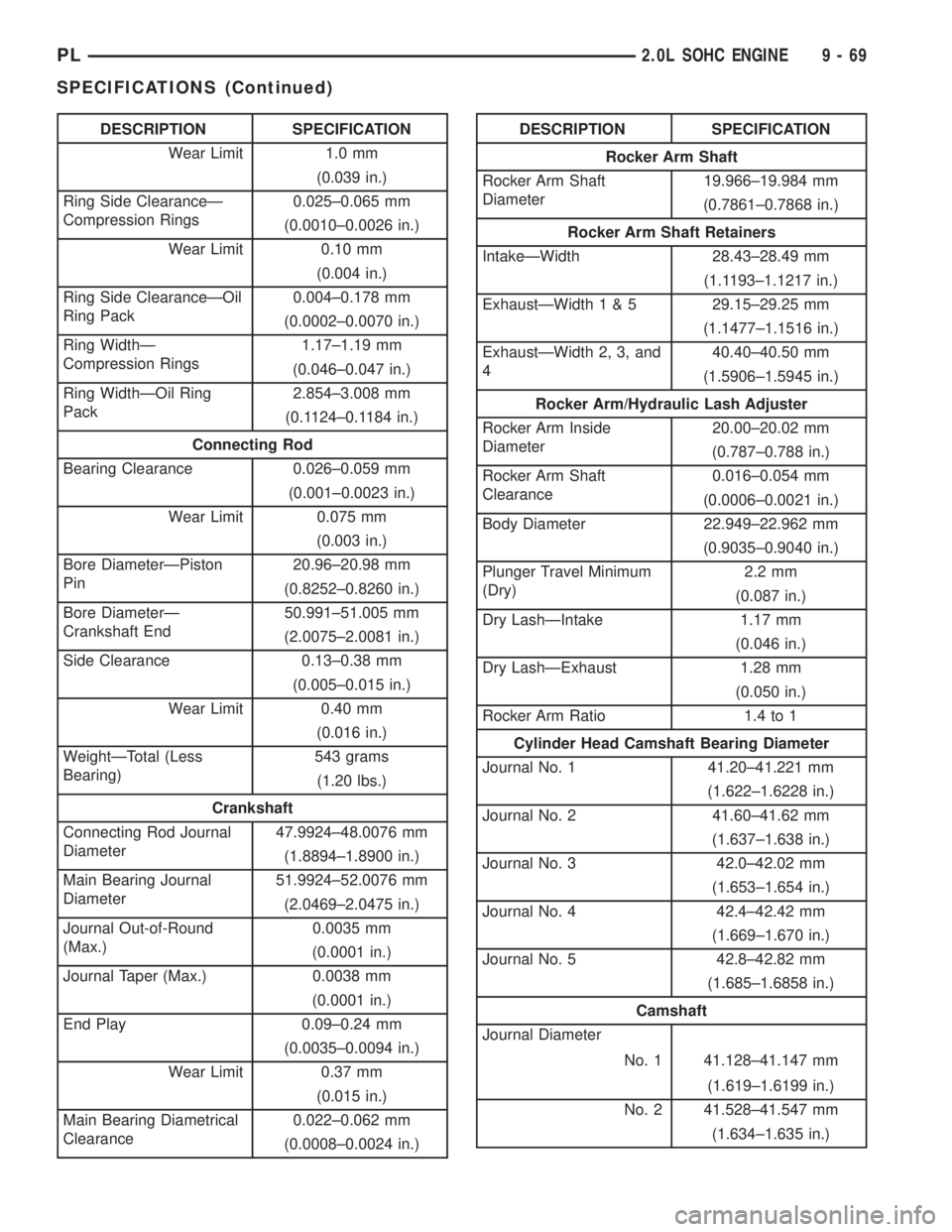
DESCRIPTION SPECIFICATION
Wear Limit 1.0 mm
(0.039 in.)
Ring Side ClearanceÐ
Compression Rings0.025±0.065 mm
(0.0010±0.0026 in.)
Wear Limit 0.10 mm
(0.004 in.)
Ring Side ClearanceÐOil
Ring Pack0.004±0.178 mm
(0.0002±0.0070 in.)
Ring WidthÐ
Compression Rings1.17±1.19 mm
(0.046±0.047 in.)
Ring WidthÐOil Ring
Pack2.854±3.008 mm
(0.1124±0.1184 in.)
Connecting Rod
Bearing Clearance 0.026±0.059 mm
(0.001±0.0023 in.)
Wear Limit 0.075 mm
(0.003 in.)
Bore DiameterÐPiston
Pin20.96±20.98 mm
(0.8252±0.8260 in.)
Bore DiameterÐ
Crankshaft End50.991±51.005 mm
(2.0075±2.0081 in.)
Side Clearance 0.13±0.38 mm
(0.005±0.015 in.)
Wear Limit 0.40 mm
(0.016 in.)
WeightÐTotal (Less
Bearing)543 grams
(1.20 lbs.)
Crankshaft
Connecting Rod Journal
Diameter47.9924±48.0076 mm
(1.8894±1.8900 in.)
Main Bearing Journal
Diameter51.9924±52.0076 mm
(2.0469±2.0475 in.)
Journal Out-of-Round
(Max.)0.0035 mm
(0.0001 in.)
Journal Taper (Max.) 0.0038 mm
(0.0001 in.)
End Play 0.09±0.24 mm
(0.0035±0.0094 in.)
Wear Limit 0.37 mm
(0.015 in.)
Main Bearing Diametrical
Clearance0.022±0.062 mm
(0.0008±0.0024 in.)DESCRIPTION SPECIFICATION
Rocker Arm Shaft
Rocker Arm Shaft
Diameter19.966±19.984 mm
(0.7861±0.7868 in.)
Rocker Arm Shaft Retainers
IntakeÐWidth 28.43±28.49 mm
(1.1193±1.1217 in.)
ExhaustÐWidth1&529.15±29.25 mm
(1.1477±1.1516 in.)
ExhaustÐWidth 2, 3, and
440.40±40.50 mm
(1.5906±1.5945 in.)
Rocker Arm/Hydraulic Lash Adjuster
Rocker Arm Inside
Diameter20.00±20.02 mm
(0.787±0.788 in.)
Rocker Arm Shaft
Clearance0.016±0.054 mm
(0.0006±0.0021 in.)
Body Diameter 22.949±22.962 mm
(0.9035±0.9040 in.)
Plunger Travel Minimum
(Dry)2.2 mm
(0.087 in.)
Dry LashÐIntake 1.17 mm
(0.046 in.)
Dry LashÐExhaust 1.28 mm
(0.050 in.)
Rocker Arm Ratio 1.4 to 1
Cylinder Head Camshaft Bearing Diameter
Journal No. 1 41.20±41.221 mm
(1.622±1.6228 in.)
Journal No. 2 41.60±41.62 mm
(1.637±1.638 in.)
Journal No. 3 42.0±42.02 mm
(1.653±1.654 in.)
Journal No. 4 42.4±42.42 mm
(1.669±1.670 in.)
Journal No. 5 42.8±42.82 mm
(1.685±1.6858 in.)
Camshaft
Journal Diameter
No. 1 41.128±41.147 mm
(1.619±1.6199 in.)
No. 2 41.528±41.547 mm
(1.634±1.635 in.)
PL2.0L SOHC ENGINE 9 - 69
SPECIFICATIONS (Continued)
Page 831 of 1285
(3) Squeeze retainer tabs together and pull fuel
tube/quick-connect fitting assembly off of fuel tube
nipple. The retainer will remain on fuel tube.
INSTALLATION
CAUTION: Never install a quick-connect fitting
without the retainer being either on the fuel tube or
already in the quick-connect fitting. In either case,
ensure the retainer locks securely into the quick-
connect fitting by firmly pulling on fuel tube and fit-
ting to ensure it is secured.
(1) Using a clean lint free cloth, clean the fuel tube
nipple and retainer.
(2) Prior to connecting the fitting to the fuel tube,
coat the fuel tube nipple with clean 30 weight engine
oil.
(3) Push the quick-connect fitting over the fuel
tube until theretainer seats and a click is heard.
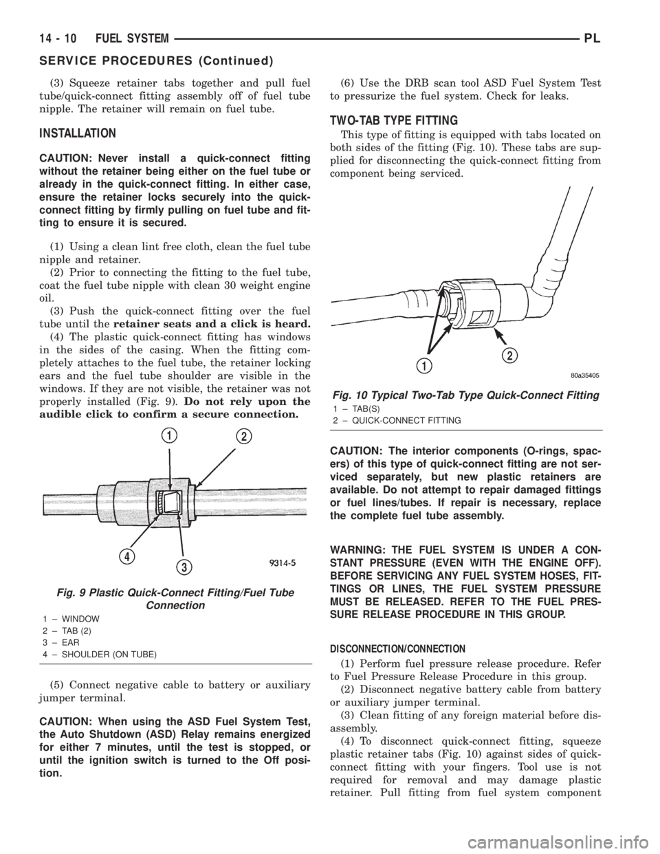
(4) The plastic quick-connect fitting has windows
in the sides of the casing. When the fitting com-
pletely attaches to the fuel tube, the retainer locking
ears and the fuel tube shoulder are visible in the
windows. If they are not visible, the retainer was not
properly installed (Fig. 9).Do not rely upon the
audible click to confirm a secure connection.
(5) Connect negative cable to battery or auxiliary
jumper terminal.
CAUTION: When using the ASD Fuel System Test,
the Auto Shutdown (ASD) Relay remains energized
for either 7 minutes, until the test is stopped, or
until the ignition switch is turned to the Off posi-
tion.(6) Use the DRB scan tool ASD Fuel System Test
to pressurize the fuel system. Check for leaks.
TWO-TAB TYPE FITTING
This type of fitting is equipped with tabs located on
both sides of the fitting (Fig. 10). These tabs are sup-
plied for disconnecting the quick-connect fitting from
component being serviced.
CAUTION: The interior components (O-rings, spac-
ers) of this type of quick-connect fitting are not ser-
viced separately, but new plastic retainers are
available. Do not attempt to repair damaged fittings
or fuel lines/tubes. If repair is necessary, replace
the complete fuel tube assembly.
WARNING:
THE FUEL SYSTEM IS UNDER A CON-
STANT PRESSURE (EVEN WITH THE ENGINE OFF).
BEFORE SERVICING ANY FUEL SYSTEM HOSES, FIT-
TINGS OR LINES, THE FUEL SYSTEM PRESSURE
MUST BE RELEASED. REFER TO THE FUEL PRES-
SURE RELEASE PROCEDURE IN THIS GROUP.
DISCONNECTION/CONNECTION
(1) Perform fuel pressure release procedure. Refer
to Fuel Pressure Release Procedure in this group.
(2) Disconnect negative battery cable from battery
or auxiliary jumper terminal.
(3) Clean fitting of any foreign material before dis-
assembly.
(4) To disconnect quick-connect fitting, squeeze
plastic retainer tabs (Fig. 10) against sides of quick-
connect fitting with your fingers. Tool use is not
required for removal and may damage plastic
retainer. Pull fitting from fuel system component
Fig. 9 Plastic Quick-Connect Fitting/Fuel Tube
Connection
1 ± WINDOW
2 ± TAB (2)
3 ± EAR
4 ± SHOULDER (ON TUBE)
Fig. 10 Typical Two-Tab Type Quick-Connect Fitting
1 ± TAB(S)
2 ± QUICK-CONNECT FITTING
14 - 10 FUEL SYSTEMPL
SERVICE PROCEDURES (Continued)
Page 851 of 1285
signal to the PCM, allowing engine starter operation.
The interlock switch is not adjustable.
Clutch Pedal Upstop Switch
With the clutch pedal at rest, the clutch pedal
upstop switch is closed, allowing speed control oper-
ation. When the clutch pedal is depressed, the upstop
switch opens and signals the PCM to cancel speed
control operation, and enter a modified engine cali-
bration schedule to improve driveability during gear-
to-gear shifts. The upstop switch is not adjustable.
CRANKSHAFT POSITION SENSORÐPCM
INPUT
DESCRIPTION
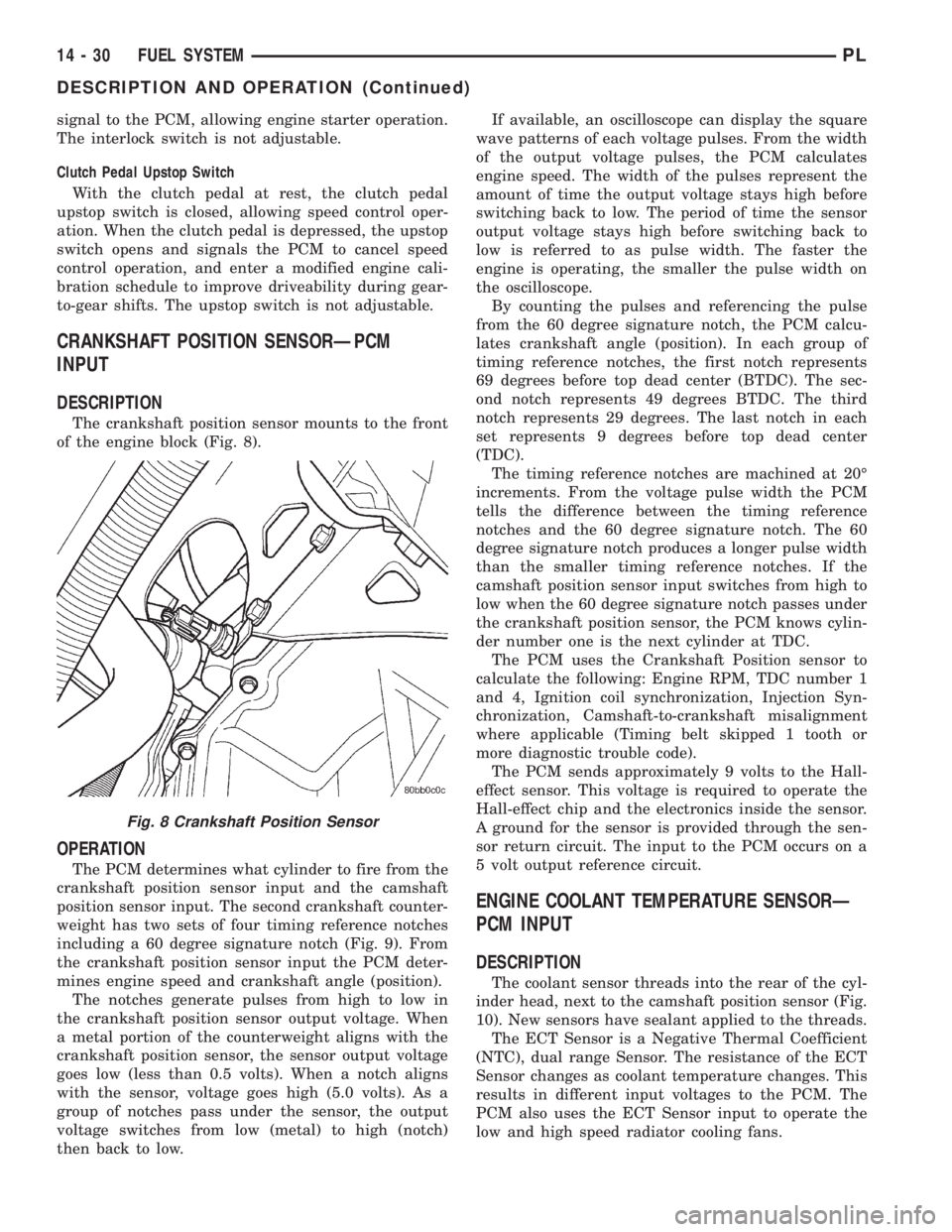
The crankshaft position sensor mounts to the front
of the engine block (Fig. 8).
OPERATION
The PCM determines what cylinder to fire from the
crankshaft position sensor input and the camshaft
position sensor input. The second crankshaft counter-
weight has two sets of four timing reference notches
including a 60 degree signature notch (Fig. 9). From
the crankshaft position sensor input the PCM deter-
mines engine speed and crankshaft angle (position).
The notches generate pulses from high to low in
the crankshaft position sensor output voltage. When
a metal portion of the counterweight aligns with the
crankshaft position sensor, the sensor output voltage
goes low (less than 0.5 volts). When a notch aligns
with the sensor, voltage goes high (5.0 volts). As a
group of notches pass under the sensor, the output
voltage switches from low (metal) to high (notch)
then back to low.If available, an oscilloscope can display the square
wave patterns of each voltage pulses. From the width
of the output voltage pulses, the PCM calculates
engine speed. The width of the pulses represent the
amount of time the output voltage stays high before
switching back to low. The period of time the sensor
output voltage stays high before switching back to
low is referred to as pulse width. The faster the
engine is operating, the smaller the pulse width on
the oscilloscope.
By counting the pulses and referencing the pulse
from the 60 degree signature notch, the PCM calcu-
lates crankshaft angle (position). In each group of
timing reference notches, the first notch represents
69 degrees before top dead center (BTDC). The sec-
ond notch represents 49 degrees BTDC. The third
notch represents 29 degrees. The last notch in each
set represents 9 degrees before top dead center
(TDC).
The timing reference notches are machined at 20É
increments. From the voltage pulse width the PCM
tells the difference between the timing reference
notches and the 60 degree signature notch. The 60
degree signature notch produces a longer pulse width
than the smaller timing reference notches. If the
camshaft position sensor input switches from high to
low when the 60 degree signature notch passes under
the crankshaft position sensor, the PCM knows cylin-
der number one is the next cylinder at TDC.
The PCM uses the Crankshaft Position sensor to
calculate the following: Engine RPM, TDC number 1
and 4, Ignition coil synchronization, Injection Syn-
chronization, Camshaft-to-crankshaft misalignment
where applicable (Timing belt skipped 1 tooth or
more diagnostic trouble code).
The PCM sends approximately 9 volts to the Hall-
effect sensor. This voltage is required to operate the
Hall-effect chip and the electronics inside the sensor.
A ground for the sensor is provided through the sen-
sor return circuit. The input to the PCM occurs on a
5 volt output reference circuit.
ENGINE COOLANT TEMPERATURE SENSORÐ
PCM INPUT
DESCRIPTION
The coolant sensor threads into the rear of the cyl-
inder head, next to the camshaft position sensor (Fig.
10). New sensors have sealant applied to the threads.
The ECT Sensor is a Negative Thermal Coefficient
(NTC), dual range Sensor. The resistance of the ECT
Sensor changes as coolant temperature changes. This
results in different input voltages to the PCM. The
PCM also uses the ECT Sensor input to operate the
low and high speed radiator cooling fans.
Fig. 8 Crankshaft Position Sensor
14 - 30 FUEL SYSTEMPL
DESCRIPTION AND OPERATION (Continued)
Page 895 of 1285
(13) If the vehicle is equipped with a power steer-
ing fluid cooler, remove the two screws securing the
cooler to the front suspension crossmember. They are
located behind the cooler and can be accessed from
above. Allow the cooler to hang out of the way.
(14) Remove the bolt mounting the engine torque
strut to the right forward corner of the front suspen-
sion crossmember (Fig. 8).
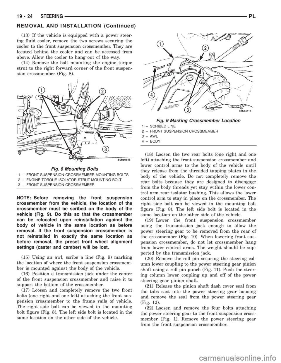
NOTE: Before removing the front suspension
crossmember from the vehicle, the location of the
crossmember must be scribed on the body of the
vehicle (Fig. 9). Do this so that the crossmember
can be relocated upon reinstallation against the
body of vehicle in the same location as before
removal. If the front suspension crossmember is
not reinstalled in exactly the same location as
before removal, the preset front wheel alignment
settings (caster and camber) will be lost.
(15) Using an awl, scribe a line (Fig. 9) marking
the location of where the front suspension crossmem-
ber is mounted against the body of the vehicle.
(16) Position a transmission jack under the center
of the front suspension crossmember and raise it to
support the bottom of the crossmember.
(17) Loosen and completely remove the two front
bolts (one right and one left) attaching the front sus-
pension crossmember to the frame rails of vehicle.
The right side bolt can be viewed in the mounting
bolt figure (Fig. 8). The left side bolt is located in the
same location on the other side of the vehicle.(18) Loosen the two rear bolts (one right and one
left) attaching the front suspension crossmember and
lower control arms to the body of the vehicle until
they release from the threaded tapping plates in the
body of the vehicle. Do not completely remove the
rear bolts because they are designed to disengage
from the body threads yet stay within the lower con-
trol arm rear isolator bushing. This allows the lower
control arm to stay in place on the crossmember. The
right side bolt can be viewed in the mounting bolt
figure (Fig. 8). The left side bolt is located in the
same location on the other side of the vehicle.
(19) Lower the front suspension crossmember
using the transmission jack enough to allow the
power steering gear to be removed from the rear of
the crossmember (Fig. 10). When lowering front sus-
pension crossmember, do not let crossmember hang
from lower control arms. The weight should be sup-
ported by the transmission jack.
(20) Remove the roll pin securing the steering col-
umn lower coupling to the power steering gear pinion
shaft using a roll pin punch (Fig. 11). Push the steer-
ing column lower coupling up and off of the power
steering gear pinion shaft.
(21) Release the pinion shaft dash cover seal from
the tabs cast into the power steering gear housing
and remove the seal from the power steering gear
(Fig. 12).
(22) Loosen and remove the four bolts attaching
the power steering gear to the front suspension cross-
member (Fig. 1). Remove the power steering gear
from the front suspension crossmember.
Fig. 8 Mounting Bolts
1 ± FRONT SUSPENSION CROSSMEMBER MOUNTING BOLTS
2 ± ENGINE TORQUE ISOLATOR STRUT MOUNTING BOLT
3 ± FRONT SUSPENSION CROSSMEMBER
Fig. 9 Marking Crossmember Location
1 ± SCRIBED LINE
2 ± FRONT SUSPENSION CROSSMEMBER
3±AWL
4 ± BODY
19 - 24 STEERINGPL
REMOVAL AND INSTALLATION (Continued)
Page 903 of 1285
REMOVAL
(1) Disconnect the negative (-) cable from the bat-
tery and isolate the cable.
(2) Before beginning removal of the steering col-
umn, be sure the front wheels of vehicle are in the
STRAIGHT-AHEAD position.
(3) Remove the screw securing the left end of the
top cover to the instrument panel. It is located just
above the left instrument panel end cap.
(4) Starting on the driver's end, push upward on
the instrument panel top cover, disengaging its
retainer clips along the face of the instrument panel.
Disengage just enough clips to allow access to the
upper ends of the instrument cluster bezel.
(5) Disengage the clips along the outer edge of the
instrument cluster bezel and remove the bezel from
the vehicle.
(6) Remove the two screws along the bottom of the
steering column cover that mounts below the steering
column on the instrument panel. Disengage the clips
on the upper end of the steering column cover and
remove the cover by pulling it straight away from the
instrument panel.
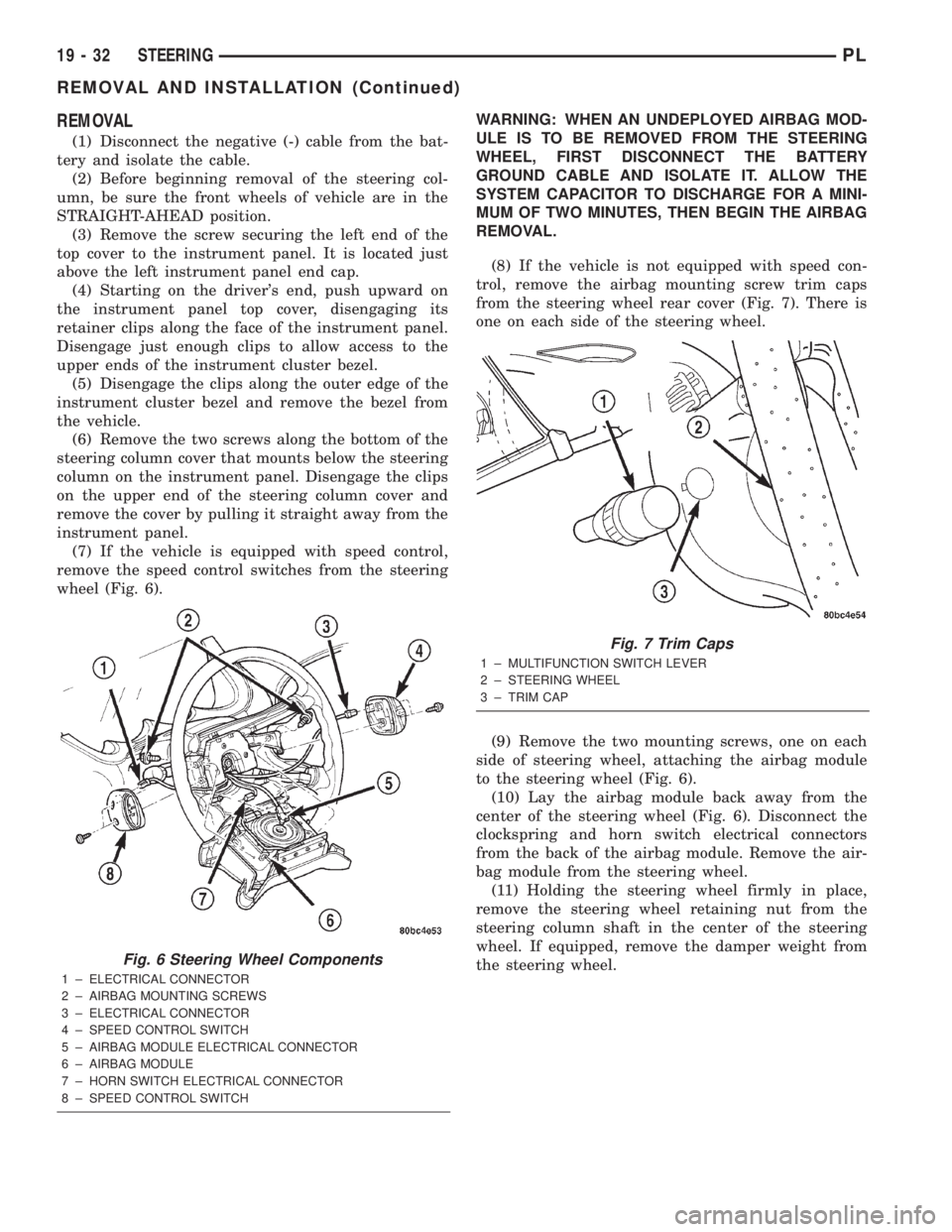
(7) If the vehicle is equipped with speed control,
remove the speed control switches from the steering
wheel (Fig. 6).WARNING: WHEN AN UNDEPLOYED AIRBAG MOD-
ULE IS TO BE REMOVED FROM THE STEERING
WHEEL, FIRST DISCONNECT THE BATTERY
GROUND CABLE AND ISOLATE IT. ALLOW THE
SYSTEM CAPACITOR TO DISCHARGE FOR A MINI-
MUM OF TWO MINUTES, THEN BEGIN THE AIRBAG
REMOVAL.
(8) If the vehicle is not equipped with speed con-
trol, remove the airbag mounting screw trim caps
from the steering wheel rear cover (Fig. 7). There is
one on each side of the steering wheel.
(9) Remove the two mounting screws, one on each
side of steering wheel, attaching the airbag module
to the steering wheel (Fig. 6).
(10) Lay the airbag module back away from the
center of the steering wheel (Fig. 6). Disconnect the
clockspring and horn switch electrical connectors
from the back of the airbag module. Remove the air-
bag module from the steering wheel.
(11) Holding the steering wheel firmly in place,
remove the steering wheel retaining nut from the
steering column shaft in the center of the steering
wheel. If equipped, remove the damper weight from
the steering wheel.
Fig. 6 Steering Wheel Components
1 ± ELECTRICAL CONNECTOR
2 ± AIRBAG MOUNTING SCREWS
3 ± ELECTRICAL CONNECTOR
4 ± SPEED CONTROL SWITCH
5 ± AIRBAG MODULE ELECTRICAL CONNECTOR
6 ± AIRBAG MODULE
7 ± HORN SWITCH ELECTRICAL CONNECTOR
8 ± SPEED CONTROL SWITCH
Fig. 7 Trim Caps
1 ± MULTIFUNCTION SWITCH LEVER
2 ± STEERING WHEEL
3 ± TRIM CAP
19 - 32 STEERINGPL
REMOVAL AND INSTALLATION (Continued)
Page 910 of 1285
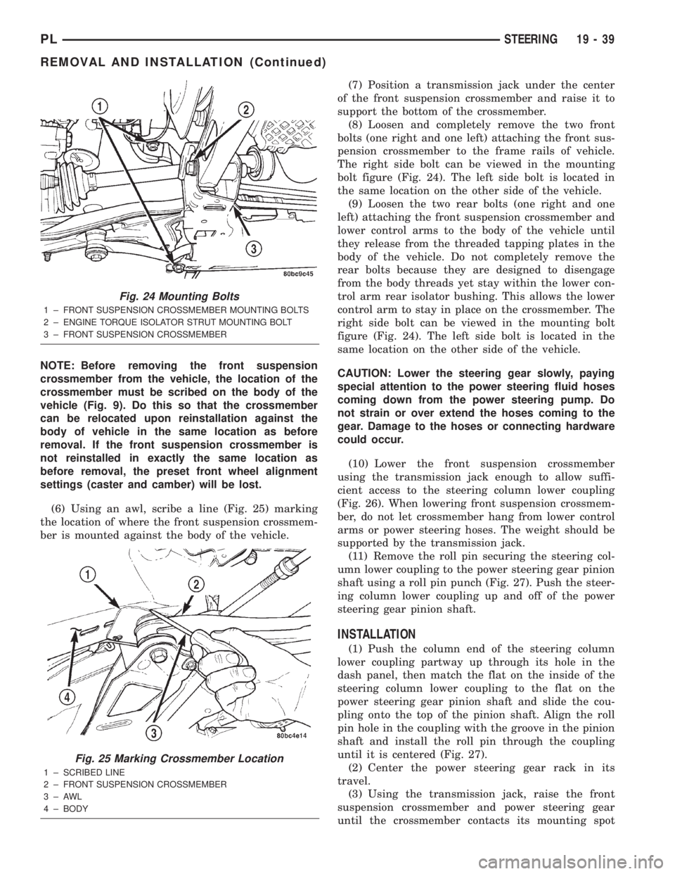
NOTE: Before removing the front suspension
crossmember from the vehicle, the location of the
crossmember must be scribed on the body of the
vehicle (Fig. 9). Do this so that the crossmember
can be relocated upon reinstallation against the
body of vehicle in the same location as before
removal. If the front suspension crossmember is
not reinstalled in exactly the same location as
before removal, the preset front wheel alignment
settings (caster and camber) will be lost.
(6) Using an awl, scribe a line (Fig. 25) marking
the location of where the front suspension crossmem-
ber is mounted against the body of the vehicle.(7) Position a transmission jack under the center
of the front suspension crossmember and raise it to
support the bottom of the crossmember.
(8) Loosen and completely remove the two front
bolts (one right and one left) attaching the front sus-
pension crossmember to the frame rails of vehicle.
The right side bolt can be viewed in the mounting
bolt figure (Fig. 24). The left side bolt is located in
the same location on the other side of the vehicle.
(9) Loosen the two rear bolts (one right and one
left) attaching the front suspension crossmember and
lower control arms to the body of the vehicle until
they release from the threaded tapping plates in the
body of the vehicle. Do not completely remove the
rear bolts because they are designed to disengage
from the body threads yet stay within the lower con-
trol arm rear isolator bushing. This allows the lower
control arm to stay in place on the crossmember. The
right side bolt can be viewed in the mounting bolt
figure (Fig. 24). The left side bolt is located in the
same location on the other side of the vehicle.
CAUTION: Lower the steering gear slowly, paying
special attention to the power steering fluid hoses
coming down from the power steering pump. Do
not strain or over extend the hoses coming to the
gear. Damage to the hoses or connecting hardware
could occur.
(10) Lower the front suspension crossmember
using the transmission jack enough to allow suffi-
cient access to the steering column lower coupling
(Fig. 26). When lowering front suspension crossmem-
ber, do not let crossmember hang from lower control
arms or power steering hoses. The weight should be
supported by the transmission jack.
(11) Remove the roll pin securing the steering col-
umn lower coupling to the power steering gear pinion
shaft using a roll pin punch (Fig. 27). Push the steer-
ing column lower coupling up and off of the power
steering gear pinion shaft.
INSTALLATION
(1) Push the column end of the steering column
lower coupling partway up through its hole in the
dash panel, then match the flat on the inside of the
steering column lower coupling to the flat on the
power steering gear pinion shaft and slide the cou-
pling onto the top of the pinion shaft. Align the roll
pin hole in the coupling with the groove in the pinion
shaft and install the roll pin through the coupling
until it is centered (Fig. 27).
(2) Center the power steering gear rack in its
travel.
(3) Using the transmission jack, raise the front
suspension crossmember and power steering gear
until the crossmember contacts its mounting spot
Fig. 24 Mounting Bolts
1 ± FRONT SUSPENSION CROSSMEMBER MOUNTING BOLTS
2 ± ENGINE TORQUE ISOLATOR STRUT MOUNTING BOLT
3 ± FRONT SUSPENSION CROSSMEMBER
Fig. 25 Marking Crossmember Location
1 ± SCRIBED LINE
2 ± FRONT SUSPENSION CROSSMEMBER
3±AWL
4 ± BODY
PLSTEERING 19 - 39
REMOVAL AND INSTALLATION (Continued)
Page 974 of 1285
CONDITION POSSIBLE CAUSES CORRECTION
SHIFTS DELAYED OR
ERRATIC (ALSO SHIFTS
HARSH AT TIMES)1. Fluid Level Low/High. 1. Correct fluid level and check for leaks if
low.
2. Fluid Filter Clogged. 2. Replace filter. If filter and fluid contained
clutch material or metal particles, an
overhaul may be necessary. Perform lube
flow test.
3. Throttle Linkage Misadjusted. 3. Adjust linkage as described in service
section.
4. Throttle Linkage Binding. 4. Check cable for binding. Check for return
to closed throttle at transmission.
5. Gearshift Linkage/Cable
Misadjusted.5. Adjust linkage/cable as described in
service section.
6. Governor Valve Sticking. 6. Inspect, clean or repair.
7. Governor Seal Rings Worn/
Damaged.7. Inspect/replace.
8. Clutch or Servo Failure. 8. Remove valve body and air test clutch,
and band servo operation. Disassemble
and repair transmission as needed.
9. Front Band Misadjusted. 9. Adjust band.
10. Pump Suction Passage Leak. 10. Check for excessive foam on dipstick
after normal driving. Check for loose pump
bolts, defective gasket. Replace pump
assembly if needed.
NO REVERSE (D RANGES
OK)1. Gearshift Linkage/Cable
Misadjusted/Damaged.1. Repair or replace linkage parts as
needed.
2. Rear Band Misadjusted/Worn. 2. Adjust band; replace.
3. Valve Body Malfunction. 3. Remove and service valve body. Replace
valve body if any valves or valve bores are
worn or damaged.
4. Rear Servo Malfunction. 4. Remove and disassemble transmission.
Replace worn/damaged servo parts as
necessary.
5. Direct Clutch in Overdrive Worn 5. Disassemble overdrive. Replace worn or
damaged parts.
6. Front Clutch Burnt. 6. Remove and disassemble transmission.
Replace worn, damaged clutch parts as
required.
HAS FIRST/REVERSE
ONLY (NO 1-2 OR 2-3
UPSHIFT)1. Governor Valve, Shaft, Weights or
Body Damaged/Stuck.1. Remove governor assembly and clean or
repair as necessary.
2. Valve Body Malfunction. 2. Stuck 1-2 shift valve or governor plug.
3. Front Servo/Kickdown Band
Damaged/Burned.3. Repair/replace.
MOVES IN 2ND OR 3RD
GEAR, ABRUPTLY
DOWNSHIFTS TO LOW1. Valve Body Malfunction. 1. Remove, clean and inspect. Look for
stuck 1-2 valve or governor plug.
2. Governor Valve Sticking. 2. Remove, clean and inspect. Replace
faulty parts.
PLTRANSAXLE 21 - 61
DIAGNOSIS AND TESTING (Continued)
Page 1063 of 1285
SPECIFICATIONS
31TH AUTOMATIC TRANSAXLE
Type .........Automatic three speed with torque
converter and integral differential
Torque Converter Diameter...... 241millimeters
(9.48 in.)
OilType .....................MopartATF+4
(Automatic Transmission Fluid) Type 9602
Cooling Method.... Water Heat Exchanger and/or
air to oil heat exchanger
Lubrication . . . Pump (internal-external gear-type)
Transmission Gear Ratios
First Gear............................2.69
Second Gear...........................1.55
Third Gear............................1.00
Reverse Gear..........................2.10
Band Adjustment
KickdownÐBacked Off From 8 N²m
(72 in. lbs.).................... 21/4Turns
Low-ReverseÐBacked Off From 5 N²m
(41 in. lbs.).................... 31/2Turns
Clutch Pack Clearances
Front Clutch (Not Adjustable)......1.27-2.79mm
(0.050-0.110 in.)
Rear Clutch.......0.71-1.10mm (0.028-0.043 in.)
End Play
Input Shaft........0.19±1.50 mm (.008±.060 in.)
Front Clutch Retainer...........0.76±2.69 mm
(.030±.106 in.)
Front Carrier.......0.89±1.45 mm (.007±.057 in.)
Front Annulus Gear . . 0.09±0.50 mm (.0035±.020 in.)
Planet Pinion.......0.15±0.59 mm (.006±.023 in.)
Reverse Drum......0.76±3.36 mm (.030±.132 in.)
Oil Pump Clearances
Outer Gear To Pocket...........0.045-0.141mm
(0.0018-0.0056 in.)
Outer Gear Side Clearance.......0.020-0.046mm
(0.0008-0.0018 in.)
Inner Gear Side Clearance.......0.020-0.046mm
(0.0008-0.0018 in.)
Tapered Roller Bearing Settings
Differential Assembly . . 6 to 12 in. lbs. Drag Torque
Output Hub.......... 0to3in.lbs. Drag Torque
Transfer Shaft.......0.002 to 0.010 in. End Play
Overall Drag At Output
Hub ............. 3to16in.lbs. Drag TorqueThrust Washers
Reaction Shaft Support (No. 1).....1.55±1.60 mm
(.061±.063 in.)
Rear Clutch Retainer (No. 2)......1.55±1.60 mm
(.061±.063 in.)
Output Shaft (No. 3) (Select)......1.98±2.03 mm
(.077±.080 in.)
Output Shaft (No. 3) (Select)......2.15±2.22 mm
(.085±.087 in.)
Output Shaft (No. 3) (Select)......2.34±2.41 mm
(.092±.095 in.)
Front Annulus (No. 4)............2.95±3.05 mm
(.116±.120 in.)
Front Carrier (Nos. 5&6).........1.22±1.28 mm
(.0948±.050 in.)
Sun Gear-Front (No. 7)...........0.85±0.91 mm
(.033±.036 in.)
Sun Gear-Rear (No. 8)...........0.85±0.91 mm
(.033±.036 in.)
Rear Carrier (Nos. 9&10).........1.22±1.28 mm
(.0948±.050 in.)
Rev. Drum (No. 11) . . 1.55±1.60 mm (.061±.063 in.)
31TH TRANSAXLE TORQUE SPECIFICATIONS
DESCRIPTION TORQUE
Bell Housing Cover Bolts.... 12N´m(105 in. lbs.)
Cooler Line Clamps.......... 2N´m(18in.lbs.)
Diff. Bear. Ret. To Case Bolt . . 34 N´m (300 in. lbs.)
Diff. Cover To Case Bolt..... 19N´m(165 in. lbs.)
Exten. Hous. To Case Bolt . . . 28 N´m (250 in. lbs.)
Drive Plate To Crankshaft
Bolts................... 95N´m(70ft.lbs.)
Drive Plate To Torque Conv.
Bolts................... 88N´m(65ft.lbs.)
Fluid Filter Screw........... 5N´m(45in.lbs.)
Governor Counterweight
Screw................. 28N´m(250 in. lbs.)
Governor To Support Bolt...... 7N´m(60in.lbs.)
Kickdown Band Adj. Lock Nut . . 47 N´m (35 ft. lbs.)
Left Motor Mount Bolts....... 54N´m(40ft.lbs.)
Manual Cable To Trans.
Case Bolt.............. 28N´m(250 in. lbs.)
Manual Control Lever Screw . . 12 N´m (105 in. lbs.)
Oil Pan To Trans. Case
Screw................. 19N´m(165 in. lbs.)
Output Gear Strap Bolts...... 23N´m(17ft.lbs.)
Output Shaft Nut......... 271N´m(200 ft. lbs.)
Park/Neutral Switch......... 34N´m(25ft.lbs.)
Pressure Check Plug......... 5N´m(45in.lbs.)
Pump To Case Bolts........ 31N´m(275 in. lbs.)
Reaction Shaft Assembly
Bolt................... 28N´m(250 in. lbs.)
Rear Cover To Case Screw . . . 19 N´m (165 in. lbs.)
Reverse Band Adj. Lock Nut . . 14 N´m (125 in. lbs.)
21 - 150 TRANSAXLEPL