2000 DODGE NEON oil level
[x] Cancel search: oil levelPage 835 of 1285
FUEL PUMP INLET STRAINER
REMOVAL
(1) Remove fuel pump module. Refer to Fuel Pump
Module Removal in this section.
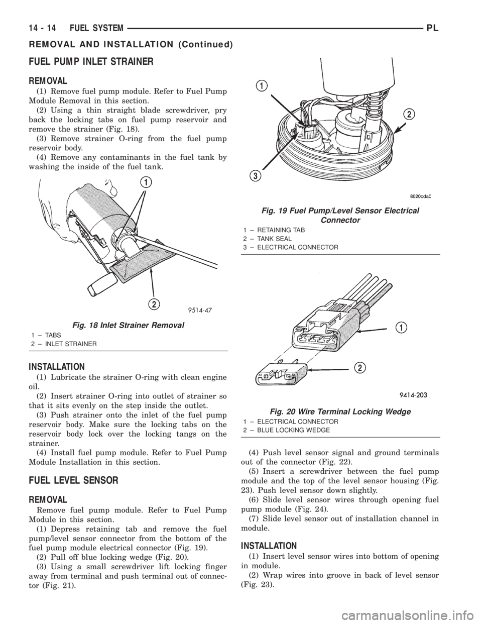
(2) Using a thin straight blade screwdriver, pry
back the locking tabs on fuel pump reservoir and
remove the strainer (Fig. 18).
(3) Remove strainer O-ring from the fuel pump
reservoir body.
(4) Remove any contaminants in the fuel tank by
washing the inside of the fuel tank.
INSTALLATION
(1) Lubricate the strainer O-ring with clean engine
oil.
(2) Insert strainer O-ring into outlet of strainer so
that it sits evenly on the step inside the outlet.
(3) Push strainer onto the inlet of the fuel pump
reservoir body. Make sure the locking tabs on the
reservoir body lock over the locking tangs on the
strainer.
(4) Install fuel pump module. Refer to Fuel Pump
Module Installation in this section.
FUEL LEVEL SENSOR
REMOVAL
Remove fuel pump module. Refer to Fuel Pump
Module in this section.
(1) Depress retaining tab and remove the fuel
pump/level sensor connector from the bottom of the
fuel pump module electrical connector (Fig. 19).
(2) Pull off blue locking wedge (Fig. 20).
(3) Using a small screwdriver lift locking finger
away from terminal and push terminal out of connec-
tor (Fig. 21).(4) Push level sensor signal and ground terminals
out of the connector (Fig. 22).
(5) Insert a screwdriver between the fuel pump
module and the top of the level sensor housing (Fig.
23). Push level sensor down slightly.
(6) Slide level sensor wires through opening fuel
pump module (Fig. 24).
(7) Slide level sensor out of installation channel in
module.
INSTALLATION
(1) Insert level sensor wires into bottom of opening
in module.
(2) Wrap wires into groove in back of level sensor
(Fig. 23).
Fig. 18 Inlet Strainer Removal
1±TABS
2 ± INLET STRAINER
Fig. 19 Fuel Pump/Level Sensor Electrical
Connector
1 ± RETAINING TAB
2 ± TANK SEAL
3 ± ELECTRICAL CONNECTOR
Fig. 20 Wire Terminal Locking Wedge
1 ± ELECTRICAL CONNECTOR
2 ± BLUE LOCKING WEDGE
14 - 14 FUEL SYSTEMPL
REMOVAL AND INSTALLATION (Continued)
Page 836 of 1285
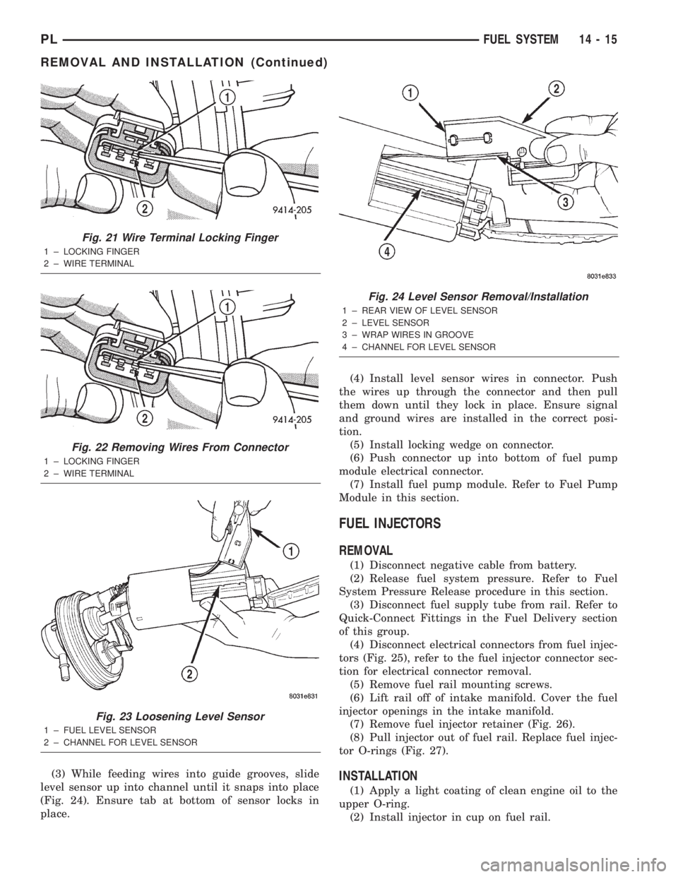
(3) While feeding wires into guide grooves, slide
level sensor up into channel until it snaps into place
(Fig. 24). Ensure tab at bottom of sensor locks in
place.(4) Install level sensor wires in connector. Push
the wires up through the connector and then pull
them down until they lock in place. Ensure signal
and ground wires are installed in the correct posi-
tion.
(5) Install locking wedge on connector.
(6) Push connector up into bottom of fuel pump
module electrical connector.
(7) Install fuel pump module. Refer to Fuel Pump
Module in this section.
FUEL INJECTORS
REMOVAL
(1) Disconnect negative cable from battery.
(2) Release fuel system pressure. Refer to Fuel
System Pressure Release procedure in this section.
(3) Disconnect fuel supply tube from rail. Refer to
Quick-Connect Fittings in the Fuel Delivery section
of this group.
(4) Disconnect electrical connectors from fuel injec-
tors (Fig. 25), refer to the fuel injector connector sec-
tion for electrical connector removal.
(5) Remove fuel rail mounting screws.
(6) Lift rail off of intake manifold. Cover the fuel
injector openings in the intake manifold.
(7) Remove fuel injector retainer (Fig. 26).
(8) Pull injector out of fuel rail. Replace fuel injec-
tor O-rings (Fig. 27).
INSTALLATION
(1) Apply a light coating of clean engine oil to the
upper O-ring.
(2) Install injector in cup on fuel rail.
Fig. 21 Wire Terminal Locking Finger
1 ± LOCKING FINGER
2 ± WIRE TERMINAL
Fig. 22 Removing Wires From Connector
1 ± LOCKING FINGER
2 ± WIRE TERMINAL
Fig. 23 Loosening Level Sensor
1 ± FUEL LEVEL SENSOR
2 ± CHANNEL FOR LEVEL SENSOR
Fig. 24 Level Sensor Removal/Installation
1 ± REAR VIEW OF LEVEL SENSOR
2 ± LEVEL SENSOR
3 ± WRAP WIRES IN GROOVE
4 ± CHANNEL FOR LEVEL SENSOR
PLFUEL SYSTEM 14 - 15
REMOVAL AND INSTALLATION (Continued)
Page 842 of 1285
FUEL INJECTION SYSTEM
TABLE OF CONTENTS
page page
DESCRIPTION AND OPERATION
INJECTION SYSTEM......................22
MODES OF OPERATION...................22
SYSTEM DIAGNOSIS......................24
POWER DISTRIBUTION CENTER............24
POWERTRAIN CONTROL MODULE...........24
PCM GROUND...........................26
5 VOLT SUPPLYÐPCM OUTPUT.............26
8-VOLT SUPPLYÐPCM OUTPUT.............26
FUEL CORRECTION or ADAPTIVE MEMORIES . . 26
PROGRAMMABLE COMMUNICATIONS
INTERFACE (PCI) BUS...................27
AIR CONDITIONING PRESSURE
TRANSDUCERÐPCM INPUT..............27
AUTOMATIC SHUTDOWN (ASD) SENSEÐ
PCM INPUT...........................27
BATTERY VOLTAGEÐPCM INPUT............28
BRAKE SWITCHÐPCM INPUT...............28
CAMSHAFT POSITION SENSORÐPCM INPUT . . 28
CLUTCH INTERLOCK/UPSTOP SWITCH.......29
CRANKSHAFT POSITION SENSORÐPCM
INPUT................................30
ENGINE COOLANT TEMPERATURE
SENSORÐPCM INPUT...................30
FUEL LEVEL SENSORÐPCM INPUT..........31
HEATED OXYGEN SENSOR (O2 SENSOR)Ð
PCM INPUT...........................32
IGNITION CIRCUIT SENSEÐPCM INPUT......34
INLET AIR TEMPERATURE SENSORÐPCM
INPUT................................34
KNOCK SENSORÐPCM INPUT..............34
MANIFOLD ABSOLUTE PRESSURE (MAP)
SENSORÐPCM INPUT...................35
POWER STEERING PRESSURE SWITCHÐ
PCM INPUT...........................35
SENSOR RETURNÐPCM INPUT.............35
SPEED CONTROLÐPCM INPUT.............36
SCI RECEIVEÐPCM INPUT.................36
PARK/NEUTRAL POSITION SWITCHÐPCM
INPUT................................36
THROTTLE POSITION SENSORÐPCM INPUT . . 36VEHICLE SPEED SIGNAL (VSS)ÐPCM INPUT . . 37
AIR CONDITIONING CLUTCH RELAYÐPCM
OUTPUT..............................38
AUTOMATIC SHUTDOWN RELAYÐPCM
OUTPUT..............................38
CHARGING SYSTEM INDICATOR LAMPÐPCM
OUTPUT..............................38
FUEL PUMP RELAYÐPCM OUTPUT..........38
PROPORTIONAL PURGE SOLENOIDÐPCM
OUTPUT..............................39
GENERATOR FIELDÐPCM OUTPUT..........39
IDLE AIR CONTROL MOTORÐPCM OUTPUT . . . 39
DATA LINK CONNECTOR...................40
FUEL INJECTORSÐPCM OUTPUT...........40
IGNITION COILÐPCM OUTPUT..............40
MALFUNCTION INDICATOR (CHECK ENGINE)
LAMPÐPCM OUTPUT...................41
SPEED CONTROLÐPCM INPUT.............41
SCI RECEIVEÐPCM OUTPUT...............41
TACHOMETERÐPCM OUTPUT..............42
TORQUE CONVERTOR CLUTCH SOLENOIDÐ
PCM OUTPUT..........................42
REMOVAL AND INSTALLATION
THROTTLE BODY........................42
THROTTLE POSITION SENSOR.............43
IDLE AIR CONTROL MOTOR................43
MAP SENSOR...........................44
POWERTRAIN CONTROL MODULE (PCM).....44
UPSTREAM HEATED OXYGEN SENSOR......45
DOWNSTREAM HEATED OXYGEN SENSOR
1/2 ..................................46
AIR CLEANER BOX.......................46
AIR CLEANER ELEMENT...................47
ENGINE COOLANT TEMPERATURE SENSOR . . . 47
VEHICLE SPEED SENSOR.................47
KNOCK SENSOR.........................48
SPECIFICATIONS
VECI LABEL.............................49
TORQUE...............................49
SPECIAL TOOLS
FUEL..................................49
PLFUEL SYSTEM 14 - 21
Page 846 of 1285
²Air Conditioning Controls
²Battery Voltage
²Inlet Air/Battery Temperature Sensor
²Brake Switch
²Camshaft Position Sensor
²Crankshaft Position Sensor
²Engine Coolant Temperature Sensor
²Fuel Level Sensor
²Ignition Switch
²Inlet Air/Intake Air Temperature Sensor
²Knock Sensor
²Manifold Absolute Pressure (MAP) Sensor
²Oxygen Sensors
²Power Steering Pressure Switch²SCI Receive
²Speed Control Switches
²Throttle Position Sensor
²Transmission Park/Neutral Switch (automatic
transmission)
²Vehicle Speed Sensor
PCM Outputs:
²Air Conditioning WOT Relay
²Auto Shutdown (ASD) Relay
²Charging Indicator Lamp
²Data Link Connector
²Proportional Purge Solenoid
²EGR Solenoid
²Fuel Injectors
²Fuel Pump Relay
²Generator Field
²Idle Air Control Motor
²Ignition Coils
²Malfunction Indicator (Check Engine) Lamp
²Radiator Fan Relay
²Speed Control Solenoids
²Tachometer
²Torque Convertor Clutch Solenoid
Based on inputs it receives, the PCM adjusts fuel
injector pulse width, idle speed, ignition spark
advance, ignition coil dwell and EVAP canister purge
operation. The PCM regulates the cooling fan, air
conditioning and speed control systems. The PCM
changes generator charge rate by adjusting the gen-
erator field. The PCM also performs diagnostics.
The PCM adjusts injector pulse width (air-fuel
ratio) based on the following inputs.
²Battery voltage
²Coolant temperature
²Inlet Air/Intake air temperature
²Exhaust gas content (oxygen sensor)
²Engine speed (crankshaft position sensor)
²Manifold absolute pressure
²Throttle position
The PCM adjusts ignition timing based on the fol-
lowing inputs.
²Coolant temperature
²Inlet Air/Intake air temperature
²Engine speed (crankshaft position sensor)
²Knock sensor
²Manifold absolute pressure
²Throttle position
²Transmission gear selection (park/neutral
switch)
The PCM also adjusts engine idle speed through
the idle air control motor based on the following
inputs.
²Air conditioning sense
²Battery voltage
²Battery temperature
²Brake switch
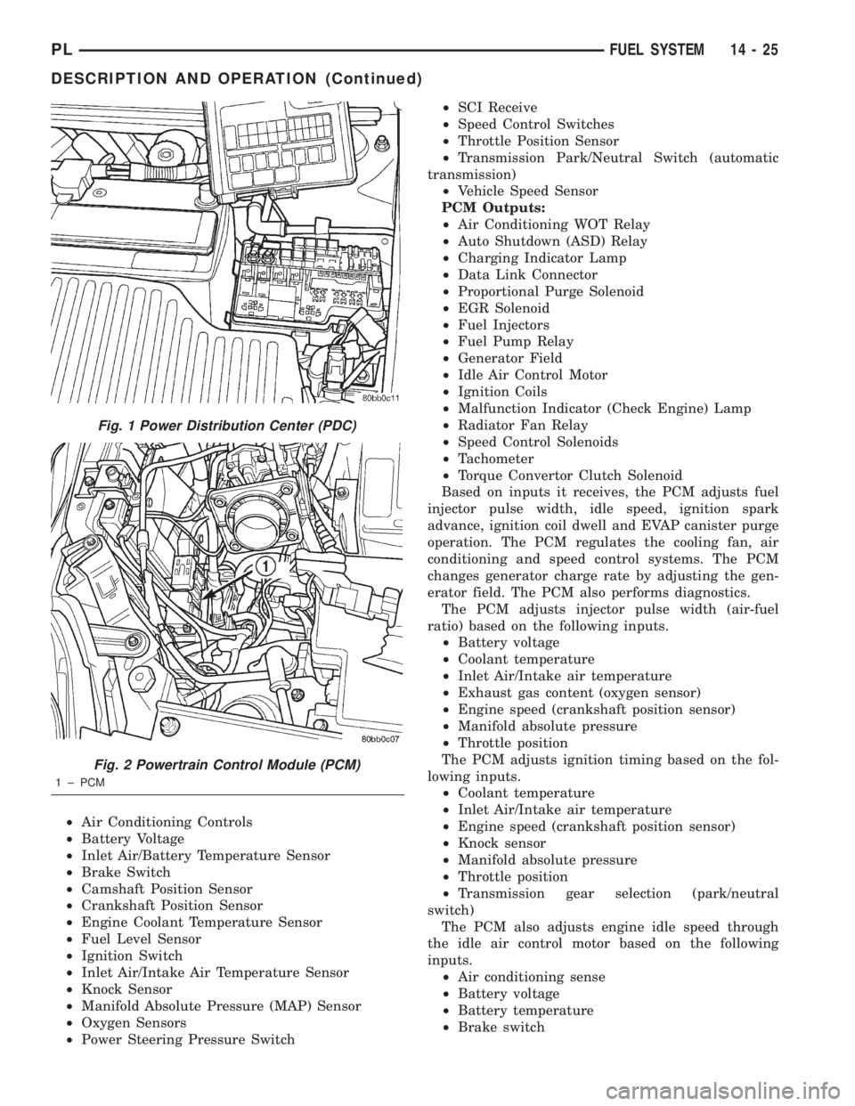
Fig. 1 Power Distribution Center (PDC)
Fig. 2 Powertrain Control Module (PCM)
1 ± PCM
PLFUEL SYSTEM 14 - 25
DESCRIPTION AND OPERATION (Continued)
Page 873 of 1285
POWER STEERING FLUID HOSES
The power steering fluid hoses connect the compo-
nents of the power steering system. They transfer
fluid from one component to the next.
The power steering fluid pressure hose is a high
pressure hose that connects the power steering pump
to the gear. At both ends of the flexible hose portion
are steel fittings that are pressure crimped to the
flexible hose. A standard tube nut fitting with an
O-ring is used at each end to connect it to either the
power steering pump or the gear.
The power steering fluid return hose is a special
rubber hose that connects the power steering gear or
the power steering fluid cooler on some models, back
to the fluid reservoir mounted on the power steering
pump. The power steering gear has a steel fitting
attached to its outlet port that the return hose is
pushed onto. On vehicles equipped with a power
steering fluid cooler, the return hose attaches to the
cooler outlet tube instead of the steering gear steel
fitting. The hose is secured to either component using
a standard adjustable clamp. The other end of the
power steering fluid return hose attaches to the
power steering fluid reservoir on the power steering
pump using a standard adjustable clamp.
POWER STEERING FLUID COOLER
Some models of this vehicle are equipped with a
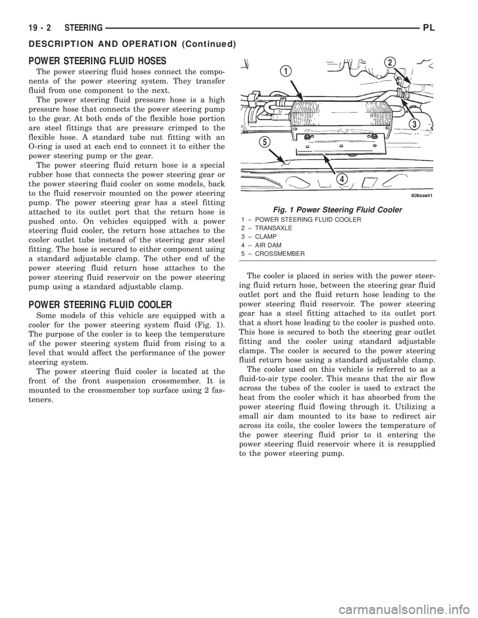
cooler for the power steering system fluid (Fig. 1).
The purpose of the cooler is to keep the temperature
of the power steering system fluid from rising to a
level that would affect the performance of the power
steering system.
The power steering fluid cooler is located at the
front of the front suspension crossmember. It is
mounted to the crossmember top surface using 2 fas-
teners.The cooler is placed in series with the power steer-
ing fluid return hose, between the steering gear fluid
outlet port and the fluid return hose leading to the
power steering fluid reservoir. The power steering
gear has a steel fitting attached to its outlet port
that a short hose leading to the cooler is pushed onto.
This hose is secured to both the steering gear outlet
fitting and the cooler using standard adjustable
clamps. The cooler is secured to the power steering
fluid return hose using a standard adjustable clamp.
The cooler used on this vehicle is referred to as a
fluid-to-air type cooler. This means that the air flow
across the tubes of the cooler is used to extract the
heat from the cooler which it has absorbed from the
power steering fluid flowing through it. Utilizing a
small air dam mounted to its base to redirect air
across its coils, the cooler lowers the temperature of
the power steering fluid prior to it entering the
power steering fluid reservoir where it is resupplied
to the power steering pump.
Fig. 1 Power Steering Fluid Cooler
1 ± POWER STEERING FLUID COOLER
2 ± TRANSAXLE
3 ± CLAMP
4 ± AIR DAM
5 ± CROSSMEMBER
19 - 2 STEERINGPL
DESCRIPTION AND OPERATION (Continued)
Page 888 of 1285
reduces the power required to drive the pump and
holds down temperature build-up.
When steering conditions exceed maximum pres-
sure requirements, such as when the wheels are
turned against the stops, the pressure built up in the
steering gear exerts pressure on the spring end of the
flow control valve. The high pressure lifts the relief
valve ball from its seat and allows oil to flow through
a trigger orifice located in the outlet fitting. This
reduces pressure on the spring end of the flow con-
trol valve which then opens and allows the oil to
return to the intake side of the pump. This action
limits maximum pressure output of the pump to a
safe level.
Under normal power steering pump operating con-
ditions, pressure requirements of the pump are below
maximum, causing the pressure relief valve to
remain closed.
POWER STEERING FLUID RESERVOIR
The power steering fluid reservoir is mounted on
the power steering pump using 3 bolts (Fig. 1). It
stores fluid for the power steering system.
The power steering fluid reservoir is considered an
integral part of the power steering pump and is not
serviced separately.
SERVICE PROCEDURES
POWER STEERING PUMP INITIAL OPERATION
CAUTION: The fluid level should be checked with
engine off to prevent injury from moving compo-
nents. Use only MoparTPower Steering Fluid. Do
not use automatic transmission fluid. Do not over-
fill.
Wipe the filler cap clean, then check the fluid level.
The dipstick should indicateCOLDwhen the fluid is
at normal temperature, approximately 21ÉC to 27ÉC
(70ÉF to 80ÉF).
(1) Fill the power steering fluid reservoir to the
proper level and let the fluid settle for at least two
minutes.
(2) Start the engine and let run for a few seconds,
then turn the engine off.
(3) Add fluid if necessary. Repeat the above proce-
dure until the fluid level remains constant after run-
ning the engine.
(4) Raise the front wheels off the ground.
(5) Start the engine. Slowly turn the steering
wheel right and left, lightly contacting the wheel
stops.
(6) Add power steering fluid if necessary.
(7) Lower the vehicle and turn the steering wheel
slowly from lock to lock.(8) Stop the engine. Check the fluid level and refill
as required.
(9) If the fluid is extremely foamy, allow the vehi-
cle to stand a few minutes and repeat the above pro-
cedure.
REMOVAL AND INSTALLATION
SERVICE WARNINGS AND CAUTIONS
WARNING: POWER STEERING FLUID, ENGINE
PARTS AND EXHAUST SYSTEM MAY BE
EXTREMELY HOT IF ENGINE HAS BEEN RUNNING.
DO NOT START ENGINE WITH ANY LOOSE OR DIS-
CONNECTED HOSES. DO NOT ALLOW HOSES TO
TOUCH HOT EXHAUST MANIFOLD OR CATALYST.
WARNING: FLUID LEVEL SHOULD BE CHECKED
WITH THE ENGINE OFF TO PREVENT PERSONAL
INJURY FROM MOVING PARTS.
CAUTION: When the system is open, cap all open
ends of the hoses, power steering pump fittings or
power steering gear ports to prevent entry of for-
eign material into the components.
NOTE: Do not use any type of automatic transmis-
sion fluid in the power steering system.
POWER STEERING PUMP
NOTE: Before proceeding with this removal and
installation procedure, review SERVICE WARNINGS
AND CAUTIONS at the beginning of REMOVAL AND
INSTALLATION in this section.
REMOVAL
(1) Remove battery cable from the negative post on
the battery.
(2) Siphon as much fluid as possible from the
power steering fluid reservoir.
(3) Remove the power steering pump drive belt
from the power steering pump pulley. Refer to
ACCESSORY DRIVE BELTS in the COOLING SYS-
TEM service manual group for the required removal
and installation procedure.
(4) Remove the hose clamp securing the return
hose to the power steering fluid reservoir. Slide the
hose off the end of the reservoir fitting. (Fig. 2).
(5) Back out the tube nut securing the power
steering fluid pressure hose to the power steering
pump and remove the hose from the pump (Fig. 2).
PLSTEERING 19 - 17
DESCRIPTION AND OPERATION (Continued)
Page 893 of 1285
NOTE: The power steering gear should not be ser-
viced or adjusted. If a malfunction or oil leak occurs
with the steering gear, the complete steering gear
needs to be replaced.
REMOVAL AND INSTALLATION
SERVICE WARNINGS AND CAUTIONS
WARNING: POWER STEERING FLUID, ENGINE
PARTS AND EXHAUST SYSTEM MAY BE
EXTREMELY HOT IF ENGINE HAS BEEN RUNNING.
DO NOT START ENGINE WITH ANY LOOSE OR DIS-
CONNECTED HOSES. DO NOT ALLOW HOSES TO
TOUCH HOT EXHAUST MANIFOLD OR CATALYST.
WARNING: FLUID LEVEL SHOULD BE CHECKED
WITH THE ENGINE OFF TO PREVENT PERSONAL
INJURY FROM MOVING PARTS.
CAUTION: When the system is open, cap all open
ends of the hoses, power steering pump fittings or
power steering gear ports to prevent entry of for-
eign material into the components.
NOTE: Do not use any type of automatic transmis-
sion fluid in the power steering system.
POWER STEERING GEAR
NOTE: Before proceeding with this removal and
installation procedure, review SERVICE WARNINGS
AND CAUTIONS at the beginning of REMOVAL AND
INSTALLATION in this section.
REMOVAL
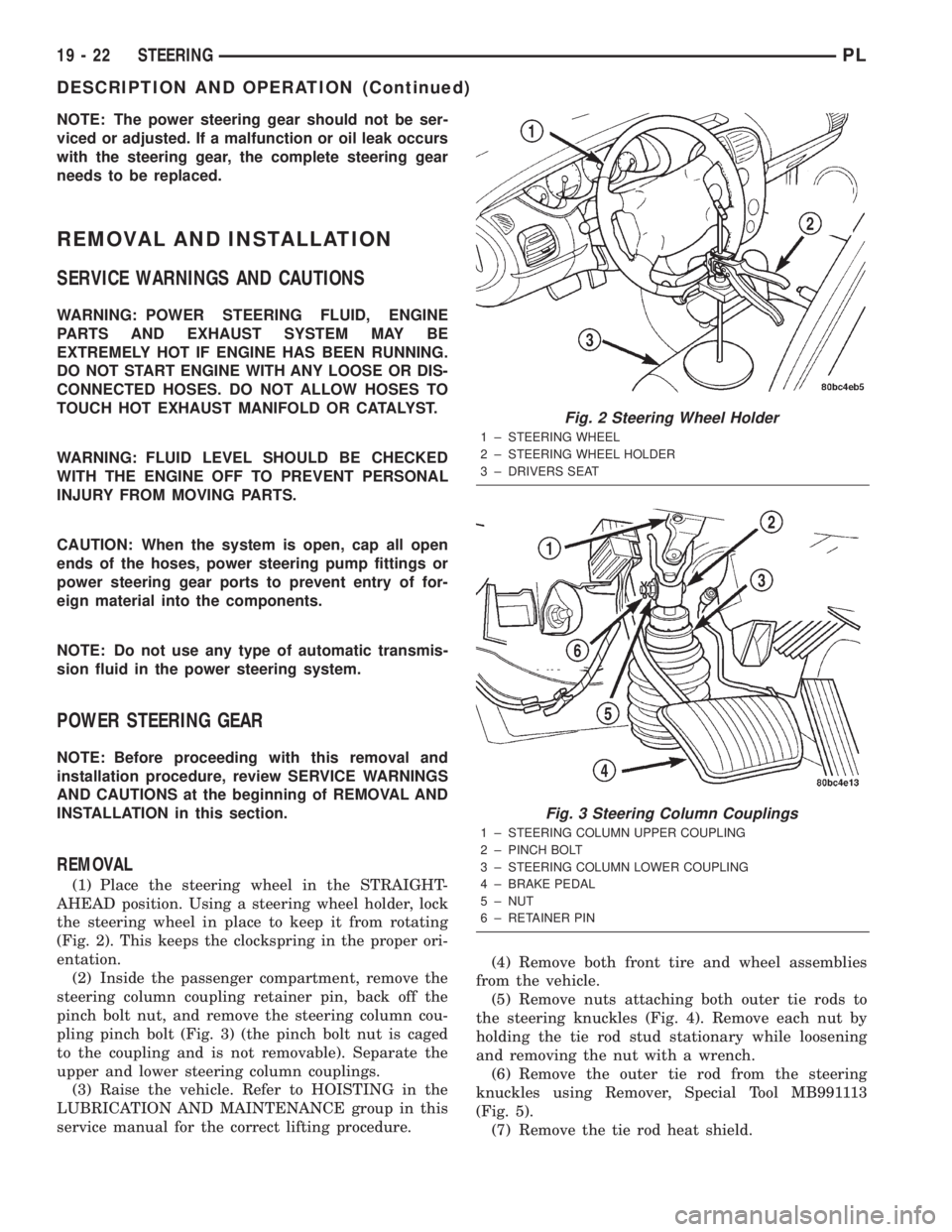
(1) Place the steering wheel in the STRAIGHT-
AHEAD position. Using a steering wheel holder, lock
the steering wheel in place to keep it from rotating
(Fig. 2). This keeps the clockspring in the proper ori-
entation.
(2) Inside the passenger compartment, remove the
steering column coupling retainer pin, back off the
pinch bolt nut, and remove the steering column cou-
pling pinch bolt (Fig. 3) (the pinch bolt nut is caged
to the coupling and is not removable). Separate the
upper and lower steering column couplings.
(3) Raise the vehicle. Refer to HOISTING in the
LUBRICATION AND MAINTENANCE group in this
service manual for the correct lifting procedure.(4) Remove both front tire and wheel assemblies
from the vehicle.
(5) Remove nuts attaching both outer tie rods to
the steering knuckles (Fig. 4). Remove each nut by
holding the tie rod stud stationary while loosening
and removing the nut with a wrench.
(6) Remove the outer tie rod from the steering
knuckles using Remover, Special Tool MB991113
(Fig. 5).
(7) Remove the tie rod heat shield.
Fig. 2 Steering Wheel Holder
1 ± STEERING WHEEL
2 ± STEERING WHEEL HOLDER
3 ± DRIVERS SEAT
Fig. 3 Steering Column Couplings
1 ± STEERING COLUMN UPPER COUPLING
2 ± PINCH BOLT
3 ± STEERING COLUMN LOWER COUPLING
4 ± BRAKE PEDAL
5 ± NUT
6 ± RETAINER PIN
19 - 22 STEERINGPL
DESCRIPTION AND OPERATION (Continued)
Page 917 of 1285
LOW LUBRICANT LEVEL
Insufficient transaxle lubricant is usually the
result of leaks, or inaccurate fluid level check or refill
method. Leakage is evident by the presence of oil
around the leak point. If leakage is not evident, the
condition is probably the result of an underfill.
If air±powered lubrication equipment is used to fill
a transaxle, be sure the equipment is properly cali-
brated. Equipment out of calibration can lead to an
underfill condition.
FLUID LEAKS
Fluid leaks can occur around the input shaft seal,
axleshaft seals, case split lines, and the end cover. Be
careful not to misdiagnose an input shaft seal leak
for an engine rear main seal leak. Also, the transaxle
case sealer (split line) will accumulate dirt and look
like an oil leak.
CLUTCH PROBLEMS
Worn, damaged, or misaligned clutch components
can cause difficult shifting, gear clash, and noise.
A worn or damaged clutch disc, pressure plate, or
release bearing can cause hard shifting and gear
clash.
SERVICE PROCEDURES
FLUID DRAIN AND FILL
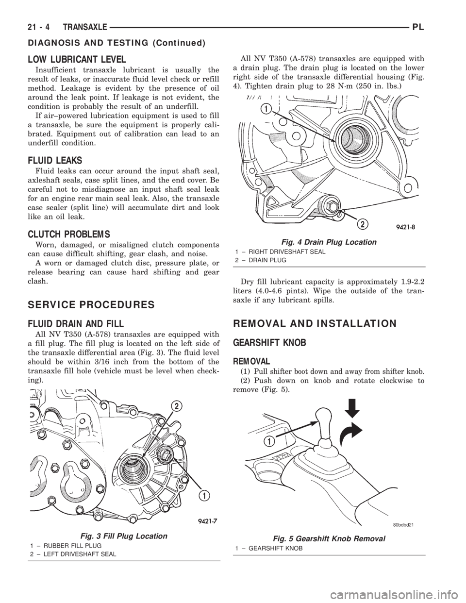
All NV T350 (A-578) transaxles are equipped with
a fill plug. The fill plug is located on the left side of
the transaxle differential area (Fig. 3). The fluid level
should be within 3/16 inch from the bottom of the
transaxle fill hole (vehicle must be level when check-
ing).All NV T350 (A-578) transaxles are equipped with
a drain plug. The drain plug is located on the lower
right side of the transaxle differential housing (Fig.
4). Tighten drain plug to 28 N´m (250 in. lbs.)
Dry fill lubricant capacity is approximately 1.9-2.2
liters (4.0-4.6 pints). Wipe the outside of the tran-
saxle if any lubricant spills.
REMOVAL AND INSTALLATION
GEARSHIFT KNOB
REMOVAL
(1)Pull shifter boot down and away from shifter knob.
(2) Push down on knob and rotate clockwise to
remove (Fig. 5).
Fig. 3 Fill Plug Location
1 ± RUBBER FILL PLUG
2 ± LEFT DRIVESHAFT SEAL
Fig. 4 Drain Plug Location
1 ± RIGHT DRIVESHAFT SEAL
2 ± DRAIN PLUG
Fig. 5 Gearshift Knob Removal
1 ± GEARSHIFT KNOB
21 - 4 TRANSAXLEPL
DIAGNOSIS AND TESTING (Continued)