2000 DODGE NEON oil level
[x] Cancel search: oil levelPage 978 of 1285
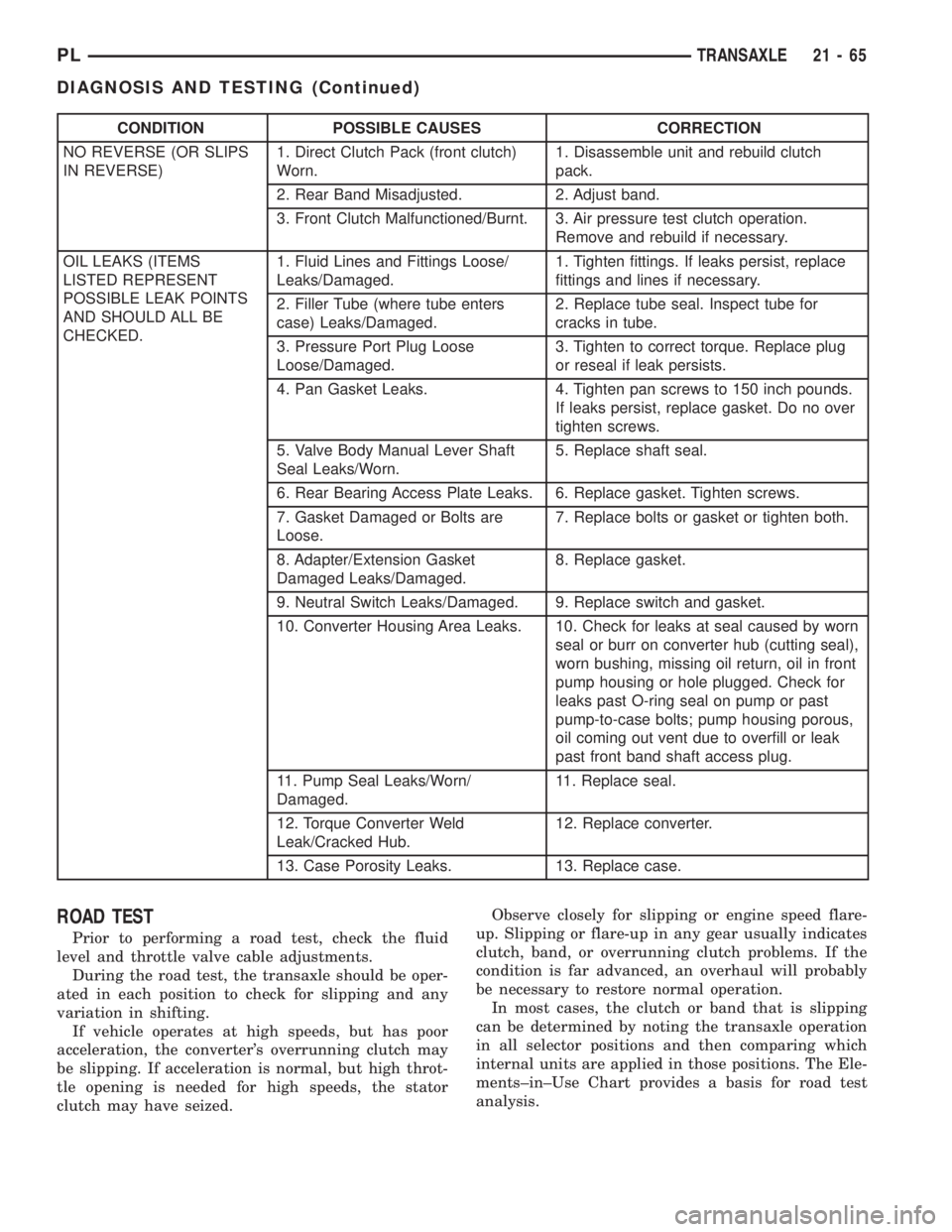
CONDITION POSSIBLE CAUSES CORRECTION
NO REVERSE (OR SLIPS
IN REVERSE)1. Direct Clutch Pack (front clutch)
Worn.1. Disassemble unit and rebuild clutch
pack.
2. Rear Band Misadjusted. 2. Adjust band.
3. Front Clutch Malfunctioned/Burnt. 3. Air pressure test clutch operation.
Remove and rebuild if necessary.
OIL LEAKS (ITEMS
LISTED REPRESENT
POSSIBLE LEAK POINTS
AND SHOULD ALL BE
CHECKED.1. Fluid Lines and Fittings Loose/
Leaks/Damaged.1. Tighten fittings. If leaks persist, replace
fittings and lines if necessary.
2. Filler Tube (where tube enters
case) Leaks/Damaged.2. Replace tube seal. Inspect tube for
cracks in tube.
3. Pressure Port Plug Loose
Loose/Damaged.3. Tighten to correct torque. Replace plug
or reseal if leak persists.
4. Pan Gasket Leaks. 4. Tighten pan screws to 150 inch pounds.
If leaks persist, replace gasket. Do no over
tighten screws.
5. Valve Body Manual Lever Shaft
Seal Leaks/Worn.5. Replace shaft seal.
6. Rear Bearing Access Plate Leaks. 6. Replace gasket. Tighten screws.
7. Gasket Damaged or Bolts are
Loose.7. Replace bolts or gasket or tighten both.
8. Adapter/Extension Gasket
Damaged Leaks/Damaged.8. Replace gasket.
9. Neutral Switch Leaks/Damaged. 9. Replace switch and gasket.
10. Converter Housing Area Leaks. 10. Check for leaks at seal caused by worn
seal or burr on converter hub (cutting seal),
worn bushing, missing oil return, oil in front
pump housing or hole plugged. Check for
leaks past O-ring seal on pump or past
pump-to-case bolts; pump housing porous,
oil coming out vent due to overfill or leak
past front band shaft access plug.
11. Pump Seal Leaks/Worn/
Damaged.11. Replace seal.
12. Torque Converter Weld
Leak/Cracked Hub.12. Replace converter.
13. Case Porosity Leaks. 13. Replace case.
ROAD TEST
Prior to performing a road test, check the fluid
level and throttle valve cable adjustments.
During the road test, the transaxle should be oper-
ated in each position to check for slipping and any
variation in shifting.
If vehicle operates at high speeds, but has poor
acceleration, the converter's overrunning clutch may
be slipping. If acceleration is normal, but high throt-
tle opening is needed for high speeds, the stator
clutch may have seized.Observe closely for slipping or engine speed flare-
up. Slipping or flare-up in any gear usually indicates
clutch, band, or overrunning clutch problems. If the
condition is far advanced, an overhaul will probably
be necessary to restore normal operation.
In most cases, the clutch or band that is slipping
can be determined by noting the transaxle operation
in all selector positions and then comparing which
internal units are applied in those positions. The Ele-
ments±in±Use Chart provides a basis for road test
analysis.
PLTRANSAXLE 21 - 65
DIAGNOSIS AND TESTING (Continued)
Page 983 of 1285
LOW AND REVERSE SERVO (REAR)
Direct air pressure into LOW/REVERSE SERVO
APPLY passage. Operation of servo is indicated by a
tightening of rear band. Spring tension on servo pis-
ton should release the band.
If clutches and servos operate properly, no upshift
indicates that a malfunction exists in the valve body.
FLUID LEAKAGE-TRANSAXLE TORQUE
CONVERTER HOUSING AREA
(1) Check for source of leakage.
(2) Since fluid leakage near the torque converter
area may be from an engine oil leak, the area should
be checked closely. Factory fill fluid is dyed red and,
therefore, can be distinguished from engine oil.
(3) Prior to removing the transaxle, perform the
following checks:
(4) When leakage is determined to originate from
the transaxle, check fluid level prior to removal of
the transaxle and torque converter.
(5) High oil level can result in oil leakage out the
vent in the dipstick. If the fluid level is high, adjust
to proper level.
(6) After performing this operation, inspect for
leakage. If a leak persists, perform the following
operation on the vehicle. This will determine if the
torque converter or transaxle is leaking.
TORQUE CONVERTER LEAKAGE
Possible sources of torque converter leakage are:
²Torque converter weld leaks at the outside diam-
eter (peripheral) weld
²Torque converter hub weld
²Torque converter impeller shell cracked adjacent
to hub
²At drive lug welds
NOTE: Hub weld is inside and not visible. Do not
attempt to repair. Replace torque converter.
BRAKE TRANSMISSION SHIFT INTERLOCK
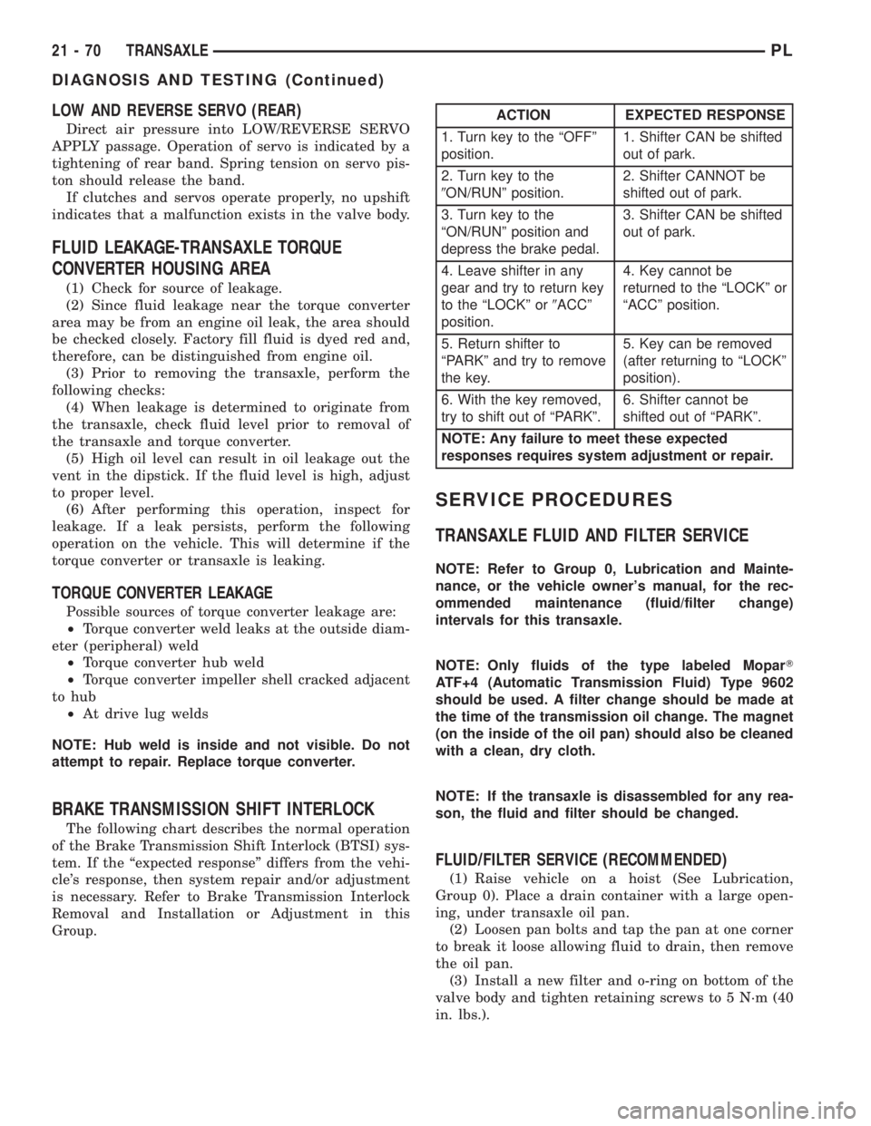
The following chart describes the normal operation
of the Brake Transmission Shift Interlock (BTSI) sys-
tem. If the ªexpected responseº differs from the vehi-
cle's response, then system repair and/or adjustment
is necessary. Refer to Brake Transmission Interlock
Removal and Installation or Adjustment in this
Group.
SERVICE PROCEDURES
TRANSAXLE FLUID AND FILTER SERVICE
NOTE: Refer to Group 0, Lubrication and Mainte-
nance, or the vehicle owner's manual, for the rec-
ommended maintenance (fluid/filter change)
intervals for this transaxle.
NOTE: Only fluids of the type labeled MoparT
ATF+4 (Automatic Transmission Fluid) Type 9602
should be used. A filter change should be made at
the time of the transmission oil change. The magnet
(on the inside of the oil pan) should also be cleaned
with a clean, dry cloth.
NOTE: If the transaxle is disassembled for any rea-
son, the fluid and filter should be changed.
FLUID/FILTER SERVICE (RECOMMENDED)
(1) Raise vehicle on a hoist (See Lubrication,
Group 0). Place a drain container with a large open-
ing, under transaxle oil pan.
(2) Loosen pan bolts and tap the pan at one corner
to break it loose allowing fluid to drain, then remove
the oil pan.
(3) Install a new filter and o-ring on bottom of the
valve body and tighten retaining screws to 5 N´m (40
in. lbs.).
ACTION EXPECTED RESPONSE
1. Turn key to the ªOFFº
position.1. Shifter CAN be shifted
out of park.
2. Turn key to the
9ON/RUNº position.2. Shifter CANNOT be
shifted out of park.
3. Turn key to the
ªON/RUNº position and
depress the brake pedal.3. Shifter CAN be shifted
out of park.
4. Leave shifter in any
gear and try to return key
to the ªLOCKº or9ACCº
position.4. Key cannot be
returned to the ªLOCKº or
ªACCº position.
5. Return shifter to
ªPARKº and try to remove
the key.5. Key can be removed
(after returning to ªLOCKº
position).
6. With the key removed,
try to shift out of ªPARKº.6. Shifter cannot be
shifted out of ªPARKº.
NOTE: Any failure to meet these expected
responses requires system adjustment or repair.
21 - 70 TRANSAXLEPL
DIAGNOSIS AND TESTING (Continued)
Page 984 of 1285
(4) Clean the oil pan and magnet. Reinstall pan
using new Mopar Silicone Adhesive sealant. Tighten
oil pan bolts to 19 N´m (165 in. lbs.).
(5) Pour four quarts of MopartATF+4 (Automatic
Transmission Fluid) Type 9602 through the dipstick
opening.
(6) Start engine and allow to idle for at least one
minute. Then, with parking and service brakes
applied, move selector lever momentarily to each
position, ending in the park or neutral position.
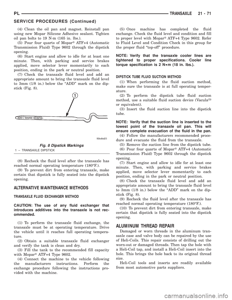
(7) Check the transaxle fluid level and add an
appropriate amount to bring the transaxle fluid level
to 3mm (1/8 in.) below the ªADDº mark on the dip-
stick (Fig. 8).
(8) Recheck the fluid level after the transaxle has
reached normal operating temperature (180ÉF.).
(9) To prevent dirt from entering transaxle, make
certain that dipstick is fully seated into the dipstick
opening.
ALTERNATIVE MAINTENANCE METHODS
TRANSAXLE FLUID EXCHANGER METHOD
CAUTION: The use of any fluid exchanger that
introduces additives into the transaxle is not rec-
ommended.
(1) To perform the transaxle fluid exchange, the
transaxle must be at operating temperature. Drive
the vehicle until it reaches full operating tempera-
ture.
(2) Obtain a suitable transaxle fluid exchanger
and verify the tank is clean and dry.
(3) Fill the tank to the recommended fill capacity
with MopartATF+4 Type 9602.
(4) Connect the machine to the vehicle following
the manufacturers instructions. Perform the
exchange procedure following the instructions pro-
vided with the machine.(5) Once machine has completed the fluid
exchange. Check the fluid level and condition and fill
to proper level with MopartATF+4 Type 9602. Refer
to Fluid Level and Condition Check in this group for
the proper fluid ªtop-offº procedure.
NOTE: Verify that the transaxle cooler lines are
tightened to proper specifications. Cooler line
torque specification is 2 N²m (18 in. lbs.).
DIPSTICK TUBE FLUID SUCTION METHOD
(1) When performing the fluid suction method,
make sure the transaxle is at full operating temper-
ature.
(2) To perform the dipstick tube fluid suction
method, use a suitable fluid suction device (Vaculay
or equivalent).
(3) Insert the fluid suction line into the dipstick
tube.
NOTE: Verify that the suction line is inserted to the
lowest point of the transaxle oil pan. This will
ensure complete evacuation of the fluid in the pan.
(4) Follow the manufacturers recommended proce-
dure and evacuate the fluid from the transaxle.
(5) Remove the suction line from the dipstick tube.
(6) Pour four quarts of MopartATF+4 (Automatic
Transmission Fluid) Type 9602 through the dipstick
opening.
(7) Start engine and allow to idle for at least one
minute. Then, with parking and service brakes
applied, move selector lever momentarily to each
position, ending in the park or neutral position.
(8) Check the transaxle fluid level and add an
appropriate amount to bring the transaxle fluid level
to 3mm (1/8 in.) below the ªADDº mark on the dip-
stick (Fig. 8).
(9) Recheck the fluid level after the transaxle has
reached normal operating temperature (180ÉF.).
(10) To prevent dirt from entering transaxle, make
certain that dipstick is fully seated into the dipstick
opening.
ALUMINUM THREAD REPAIR
Damaged or worn threads in the aluminum tran-
saxle case and valve body can be repaired by the use
of Heli-Coils. This repair consists of drilling out the
worn-out or damaged threads. Then tap the hole with
a Heli-Coil tap, and install a Heli-Coil insert into the
hole. This brings the hole back to its original thread
size.
Heli-Coil tools and inserts are readily available
from most automotive parts suppliers.
Fig. 8 Dipstick Markings
1 ± TRANSAXLE DIPSTICK
PLTRANSAXLE 21 - 71
SERVICE PROCEDURES (Continued)
Page 985 of 1285
FLUSHING COOLERS AND TUBES
When a transaxle failure has contaminated the
fluid, the transaxle oil cooler(s) must be flushed (both
radiator and remote). The cooler bypass valve in the
transaxle must be replaced also. The torque con-
verter must also be replaced with an exchange unit.
This will ensure that metal particles or sludged oil
are not later transferred back into the reconditioned
(or replaced) transaxle.
The recommended procedure for flushing the cool-
ers and tubes is to use Tool 6906A Cooler Flusher.
WARNING: WEAR PROTECTIVE EYEWEAR THAT
MEETS THE REQUIREMENTS OF OSHA AND ANSI
Z87.1±1968. WEAR STANDARD INDUSTRIAL RUB-
BER GLOVES.
KEEP LIT CIGARETTES, SPARKS, FLAMES, AND
OTHER IGNITION SOURCES AWAY FROM THE
AREA TO PREVENT THE IGNITION OF COMBUSTI-
BLE LIQUIDS AND GASES. KEEP A CLASS (B) FIRE
EXTINGUISHER IN THE AREA WHERE THE
FLUSHER WILL BE USED.
KEEP THE AREA WELL VENTILATED.
DO NOT LET FLUSHING SOLVENT COME IN CON-
TACT WITH YOUR EYES OR SKIN: IF EYE CONTAM-
INATION OCCURS, FLUSH EYES WITH WATER FOR
15 TO 20 SECONDS. REMOVE CONTAMINATED
CLOTHING AND WASH AFFECTED SKIN WITH
SOAP AND WATER. SEEK MEDICAL ATTENTION.
COOLER FLUSH USING TOOL 6906A
(1) Remove cover plate filler plug on Tool 6906A.
Fill reservoir 1/2 to 3/4 full of fresh flushing solution.
Flushing solvents are petroleum based solutions gen-
erally used to clean automatic transmission compo-
nents.DO NOTuse solvents containing acids, water,
gasoline, or any other corrosive liquids.
(2) Reinstall filler plug on Tool 6906A.
(3) Verify pump power switch is turned OFF. Con-
nect red alligator clip to positive (+) battery post.
Connect black (-) alligator clip to a good ground.
(4) Disconnect the cooler lines at the transmission.
NOTE: When flushing transmission cooler and
lines, ALWAYS reverse flush.
(5) Connect the BLUE pressure line to the OUT-
LET (From) cooler line.
(6) Connect the CLEAR return line to the INLET
(To) cooler line
(7) Turn pump ON for two to three minutes to
flush cooler(s) and lines. Monitor pressure readingsand clear return lines. Pressure readings should sta-
bilize below 20 psi. for vehicles equipped with a sin-
gle cooler and 30 psi. for vehicles equipped with dual
coolers. If flow is intermittent or exceeds these pres-
sures, replace cooler.
(8) Turn pump OFF.
(9) Disconnect CLEAR suction line from reservoir
at cover plate. Disconnect CLEAR return line at
cover plate, and place it in a drain pan.
(10) Turn pump ON for 30 seconds to purge flush-
ing solution from cooler and lines. Turn pump OFF.
(11) Place CLEAR suction line into a one quart
container of MopartATF+4 (Automatic Transmission
Fluid) Type 9602.
(12) Turn pump ON until all transmission fluid is
removed from the one quart container and lines. This
purges any residual cleaning solvent from the trans-
mission cooler and lines. Turn pump OFF.
(13) Disconnect alligator clips from battery. Recon-
nect flusher lines to cover plate, and remove flushing
adapters from cooler lines.
OIL PUMP VOLUME CHECK
After the new or repaired transmission has been
installed, fill to the proper level with MopartATF+4
(Automatic Transmission Fluid) Type 9602. The vol-
ume should be checked using the following proce-
dure:
(1) Disconnect theFrom coolerline at the trans-
mission and place a collecting container under the
disconnected line.
CAUTION: With the fluid set at the proper level,
fluid collection should not exceed (1) quart or inter-
nal damage to the transmission may occur.
(2) Run the engineat curb idle speed, with the
shift selector in neutral.
(3) If fluid flow is intermittent or it takes more
than 20 seconds to collect one quart of ATF, discon-
nect theTo Coolerline at the transaxle.
(4) Refill the transaxle to proper level and recheck
pump volume.
(5) If flow is found to be within acceptable limits,
replace the cooler. Then fill transmission to the
proper level, using MopartATF+4 (Automatic Trans-
mission Fluid) Type 9602.
(6) If fluid flow is still found to be inadequate,
check the line pressure using the Transaxle Hydrau-
lic Pressure Test procedure.
21 - 72 TRANSAXLEPL
SERVICE PROCEDURES (Continued)
Page 997 of 1285
PARK/NEUTRAL STARTING AND BACK-UP
LAMP SWITCH
TEST
The park/neutral starting switch is the center ter-
minal of the three terminal switch. It provides
ground for the starter solenoid circuit through the
selector lever in PARK and NEUTRAL positions only.
(1) To test switch, remove wiring connector from
switch and test for continuity between center pin of
switch and transaxle case. Continuity should exist
only when transaxle is in PARK or NEUTRAL.
(2) Check gearshift cable adjustment before replac-
ing a switch that tests bad.
REMOVAL
(1) Unscrew switch from transaxle case allowing
fluid to drain into a container. Move selector lever to
PARK, then to NEUTRAL position, and inspect to see
the switch operating lever fingers are centered in
switch opening.
INSTALLATION
(1) Screw the switch with a new seal into tran-
saxle case and tighten to 33 N´m (24 ft. lbs.). Retest
switch with the test lamp.
(2) Add fluid to transaxle to bring up to proper
level.
(3) The back-up lamp switch circuit is through the
two outside terminals of the three terminal switch.
(4) To test switch, remove wiring connector from
switch and test for continuity between the two out-
side pins.
(5) Continuity should exist only with transaxle in
REVERSE position.
(6) No continuity should exist from either pin to
the case.
TRANSAXLE AND TORQUE CONVERTER
REMOVAL
(1) Raise hood.
(2) Disconnect both battery cables, remove battery
hold down clamp and bolt, and remove battery.
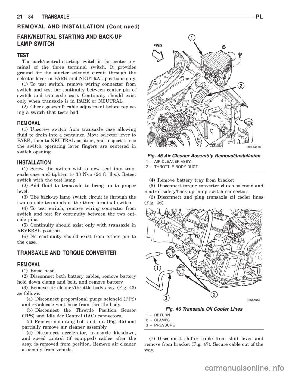
(3) Remove air cleaner/throttle body assy. (Fig. 45)
as follows:
(a) Disconnect proportional purge solenoid (PPS)
and crankcase vent hose from throttle body.
(b) Disconnect the Throttle Position Sensor
(TPS) and Idle Air Control (IAC) connectors.
(c) Remove mounting bolt and nut (Fig. 45) and
partially remove air cleaner assembly.
(d) Disconnect accelerator, transaxle kickdown,
and speed control (if equipped) cables after the
assy. is removed from position. Remove air cleaner
assembly from vehicle.(4) Remove battery tray from bracket.
(5) Disconnect torque converter clutch solenoid and
neutral safety/back-up lamp switch connectors.
(6) Disconnect and plug transaxle oil cooler lines
(Fig. 46).
(7) Disconnect shifter cable from shift lever and
remove from bracket (Fig. 47). Secure cable out of the
way.
Fig. 45 Air Cleaner Assembly Removal/Installation
1 ± AIR CLEANER ASSY.
2 ± THROTTLE BODY DUCT
Fig. 46 Transaxle Oil Cooler Lines
1 ± RETURN
2 ± CLAMPS
3 ± PRESSURE
21 - 84 TRANSAXLEPL
REMOVAL AND INSTALLATION (Continued)
Page 1001 of 1285
(c) Tighten the collar-to-transaxle bolts to 108
N´m (80 ft. lbs.) torque.
(d) Final torque the collar-to-oil pan bolts to 54
N´m (40 ft. lbs.) torque.
(11) Install both front axle driveshafts. Refer to
Group 3, Differential and Driveline for the correct
procedures.
(12) Connect vehicle speed sensor connector (Fig.
50).
(13) Install right lateral bending brace and tighten
bolts to 81 N´m (60 ft. lbs.) torque.
(14) Lower vehicle.
(15) Connect transaxle cooler lines and tighten
clamps (Fig. 46).
(16) Connect torque converter clutch solenoid and
neutral safety/back-up lamp switch connectors.
(17) Install transaxle dipstick tube.
(18) Install gear shift cable to bracket and connect
to shift lever (Fig. 47).
(19) Install transaxle kickdown cable to bracket
and lever as shown in (Fig. 48).
(20) Install battery lower tray and battery, and
tighten battery hold down clamp to secure battery.
(21) Install the air cleaner/throttle body assy. as
follows:
(a) Connect the accelerator, transaxle kickdown,
and speed control (if equipped) cables to the air
cleaner/throttle body assy.
(b) Install assy into position and tighten fasten-
ers to 14 N´m (120 in. lbs.) torque.
(c) Connect the Throttle Position Sensor (TPS)
and Idle Air Control (IAC) connectors.
(d) Connect proportional purge solenoid (PPS)
and crankcase vent hose from throttle body.
(22) Fill transaxle with a suitable amount of
ATF+4.
(23) Road test vehicle.
(24) Check for leaks, inspect fluid level, and adjust
as necessary.
PUMP OIL SEAL
The pump oil seal can be replaced without remov-
ing the pump and reaction shaft support assembly
from the transaxle case.
REMOVAL
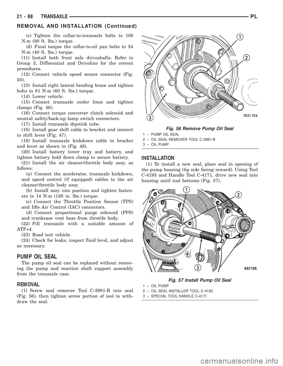
(1) Screw seal remover Tool C-3981-B into seal
(Fig. 56), then tighten screw portion of tool to with-
draw the seal.
INSTALLATION
(1) To install a new seal, place seal in opening of
the pump housing (lip side facing inward). Using Tool
C-4193 and Handle Tool C-4171, drive new seal into
housing until tool bottoms (Fig. 57).
Fig. 56 Remove Pump Oil Seal
1 ± PUMP OIL SEAL
2 ± OIL SEAL REMOVER TOOL C-3981-B
3 ± OIL PUMP
Fig. 57 Install Pump Oil Seal
1 ± OIL PUMP
2 ± OIL SEAL INSTALLER TOOL C-4193
3 ± SPECIAL TOOL HANDLE C-4171
21 - 88 TRANSAXLEPL
REMOVAL AND INSTALLATION (Continued)
Page 1096 of 1285
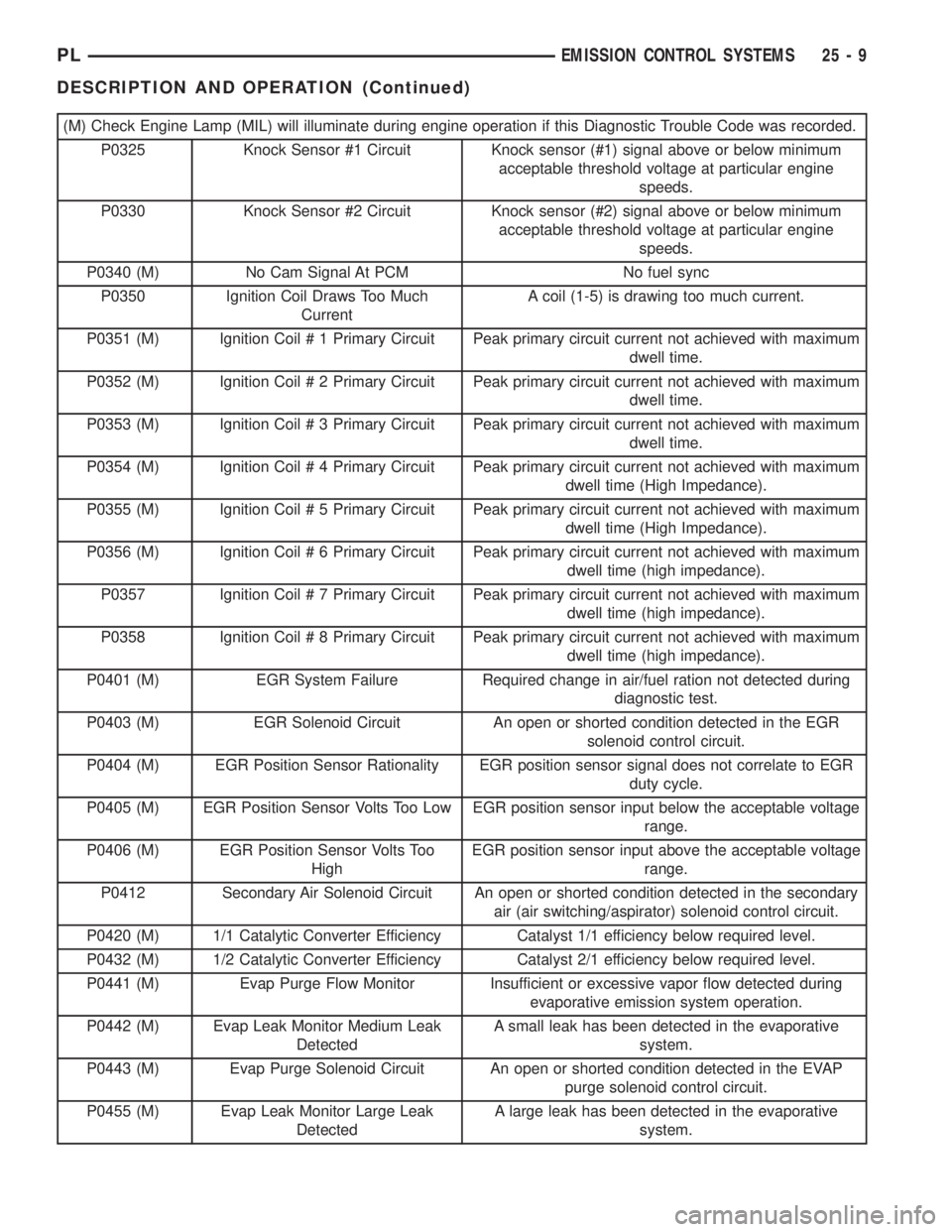
(M) Check Engine Lamp (MIL) will illuminate during engine operation if this Diagnostic Trouble Code was recorded.
P0325 Knock Sensor #1 Circuit Knock sensor (#1) signal above or below minimum
acceptable threshold voltage at particular engine
speeds.
P0330 Knock Sensor #2 Circuit Knock sensor (#2) signal above or below minimum
acceptable threshold voltage at particular engine
speeds.
P0340 (M) No Cam Signal At PCM No fuel sync
P0350 Ignition Coil Draws Too Much
CurrentA coil (1-5) is drawing too much current.
P0351 (M) Ignition Coil # 1 Primary Circuit Peak primary circuit current not achieved with maximum
dwell time.
P0352 (M) Ignition Coil # 2 Primary Circuit Peak primary circuit current not achieved with maximum
dwell time.
P0353 (M) Ignition Coil # 3 Primary Circuit Peak primary circuit current not achieved with maximum
dwell time.
P0354 (M) Ignition Coil # 4 Primary Circuit Peak primary circuit current not achieved with maximum
dwell time (High Impedance).
P0355 (M) Ignition Coil # 5 Primary Circuit Peak primary circuit current not achieved with maximum
dwell time (High Impedance).
P0356 (M) Ignition Coil # 6 Primary Circuit Peak primary circuit current not achieved with maximum
dwell time (high impedance).
P0357 Ignition Coil # 7 Primary Circuit Peak primary circuit current not achieved with maximum
dwell time (high impedance).
P0358 Ignition Coil # 8 Primary Circuit Peak primary circuit current not achieved with maximum
dwell time (high impedance).
P0401 (M) EGR System Failure Required change in air/fuel ration not detected during
diagnostic test.
P0403 (M) EGR Solenoid Circuit An open or shorted condition detected in the EGR
solenoid control circuit.
P0404 (M) EGR Position Sensor Rationality EGR position sensor signal does not correlate to EGR
duty cycle.
P0405 (M) EGR Position Sensor Volts Too Low EGR position sensor input below the acceptable voltage
range.
P0406 (M) EGR Position Sensor Volts Too
HighEGR position sensor input above the acceptable voltage
range.
P0412 Secondary Air Solenoid Circuit An open or shorted condition detected in the secondary
air (air switching/aspirator) solenoid control circuit.
P0420 (M) 1/1 Catalytic Converter Efficiency Catalyst 1/1 efficiency below required level.
P0432 (M) 1/2 Catalytic Converter Efficiency Catalyst 2/1 efficiency below required level.
P0441 (M) Evap Purge Flow Monitor Insufficient or excessive vapor flow detected during
evaporative emission system operation.
P0442 (M) Evap Leak Monitor Medium Leak
DetectedA small leak has been detected in the evaporative
system.
P0443 (M) Evap Purge Solenoid Circuit An open or shorted condition detected in the EVAP
purge solenoid control circuit.
P0455 (M) Evap Leak Monitor Large Leak
DetectedA large leak has been detected in the evaporative
system.
PLEMISSION CONTROL SYSTEMS 25 - 9
DESCRIPTION AND OPERATION (Continued)
Page 1097 of 1285

(M) Check Engine Lamp (MIL) will illuminate during engine operation if this Diagnostic Trouble Code was recorded.
P0456 Evap Leak Monitor Small Leak
Detected
P0460 Fuel Level Unit No Change Over
MilesNo movement of fuel level sender detected.
P0461 Fuel Level Unit No Changeover
TimeNo level of fuel level sender detected.
P0462 Fuel Level Sending Unit Volts Too
LowFuel level sensor input below acceptable voltage.
P0463 Fuel Level Sending Unit Volts Too
HighFuel level sensor input above acceptable voltage.
P0500 (M) No Vehicle Speed Sensor Signal No vehicle speed sensor signal detected during road
load conditions.
P0505 (M) Idle Air Control Motor Circuits Replace
P0522 Oil Pressure Sens Low Oil pressure sensor input below acceptable voltage.
P0523 Oil Pressure Sens High Oil pressure sensor input above acceptable voltage.
P0551 (M) Power Steering Switch Failure Incorrect input state detected for the power steering
switch circuit. PL: High pressure seen at high speed.
P0600 (M) PCM Failure SPI Communications No communication detected between co-processors in
the control module.
P0601 (M) Internal Controller Failure Internal control module fault condition (check sum)
detected.
P0604 Internal Trans Controller Transmission control module RAM self test fault
detected. -Aisin transmission.
P0605 Internal Trans Controller Transmission control module ROM self test fault
detected -Aisin transmission.
P0622 (G) Generator Field Not Switching
ProperlyAn open or shorted condition detected in the generator
field control circuit.
P0645 A/C Clutch Relay Circuit An open or shorted condition detected in the A/C clutch
relay control circuit.
P0700 (M) EATX Controller DTC Present This SBEC III or JTEC DTC indicates that the EATX or
Aisin controller has an active fault and has illuminated
the MIL via a CCD (EATX) or SCI (Aisin) message. The
specific fault must be acquired from the EATX via CCD
or from the Aisin via ISO-9141.
P0703 (M) Brake Switch Stuck Pressed or
ReleasedIncorrect input state detected in the brake switch circuit.
(Changed from P1595).
P0711 Trans Temp Sensor, No Temp Rise
After StartRelationship between the transmission temperature and
overdrive operation and/or TCC operation indicates a
failure of the Transmission Temperature Sensor. OBD II
Rationality.
P0712 Trans Temp Sensor Voltage Too
LowTransmission fluid temperature sensor input below
acceptable voltage.
P0713 Trans Temp Sensor Voltage Too
HighTransmission fluid temperature sensor input above
acceptable voltage.
P0720 Low Output SPD Sensor RPM,
Above 15 MPHThe relationship between the Output Shaft Speed
Sensor and vehicle speed is not within acceptable
limits.
25 - 10 EMISSION CONTROL SYSTEMSPL
DESCRIPTION AND OPERATION (Continued)