2000 DODGE NEON oil level
[x] Cancel search: oil levelPage 732 of 1285

should not be disassembled to determine the
cause of low compression unless some malfunc-
tion is present.
(11) Clean or replace spark plugs as necessary and
adjust gap as specified in Group 8, Electrical.
Tighten to specifications.
(12) Test resistance of spark plug cables. Refer to
Group 8, Electrical Ignition System Secondary Cir-
cuit Inspection.
(13) Test coil output voltage, primary and second-
ary resistance. Replace parts as necessary. Refer to
Group 8, Electrical Ignition System.
(14) Check fuel pump pressure at idle and differ-
ent RPM ranges. Refer to Group 14, Fuel System for
Specifications.
(15) The air filter elements should be replaced as
specified in Group 0, Lubrication and Maintenance.
(16) Inspect crankcase ventilation system as out
lined in Group 0, Lubrication and Maintenance. For
emission controls see Group 25, Emission Controls
for service procedures.
(17) Inspect and adjust accessory belt drives refer-
ring to Group 7, Cooling System, Accessory Drive
Belts for proper adjustments.
(18) Road test vehicle as a final test.
CYLINDER COMBUSTION PRESSURE LEAKAGE
TEST
The combustion pressure leakage test provides an
accurate means for determining engine condition.
Combustion pressure leakage testing will detect:
²Exhaust and intake valve leaks (improper seat-
ing).
²Leaks between adjacent cylinders or into water
jacket.
²Any causes for combustion/compression pressure
loss.
WARNING: DO NOT REMOVE THE RADIATOR CAP
WITH THE SYSTEM HOT AND UNDER PRESSURE
BECAUSE SERIOUS BURNS FROM COOLANT CAN
OCCUR.
Check the coolant level and fill as required. DO
NOT install the radiator cap.
Start and operate the engine until it attains nor-
mal operating temperature, then turn the engine
OFF.
Clean spark plug recesses with compressed air.
Remove the spark plugs.
Remove the oil filler cap.
Remove the air cleaner.
Calibrate the tester according to the manufactur-
er's instructions. The shop air source for testing
should maintain 483 kPa (70 psi) minimum, 1,379kPa (200 psi) maximum, with 552 kPa (80 psi) rec-
ommended.
Perform the test procedures on each cylinder
according to the tester manufacturer's instructions.
While testing, listen for pressurized air escaping
through the throttle body, tailpipe and oil filler cap
opening. Check for bubbles in the radiator coolant.
All gauge pressure indications should be equal,
with no more than 25% leakage per cylinder.
FOR EXAMPLE:At 552 kPa (80 psi) input pres-
sure, a minimum of 414 kPa (60 psi) should be main-
tained in the cylinder.
LASH ADJUSTER (TAPPET) NOISE DIAGNOSIS
A tappet-like noise may be produced from several
items. Check the following items.
(1) Engine oil level too high or too low. This may
cause aerated oil to enter the adjusters and cause
them to be spongy.
(2) Insufficient running time after rebuilding cylin-
der head. Low speed running up to 1 hour may be
required.
(3) During this time, turn engine off and let set for
a few minutes before restarting. Repeat this several
times after engine has reached normal operating
temperature.
(4) Low oil pressure.
(5) The oil restrictor pressed into the vertical oil
passage to the cylinder head is plugged with debris.
(6) Air ingested into oil due to broken or cracked
oil pump pick up.
(7) Worn valve guides.
(8) Rocker arm ears contacting valve spring
retainer.
(9) Rocker arm loose, adjuster stuck or at maxi-
mum extension and still leaves lash in the system.
(10) Faulty lash adjuster.
a. Check lash adjusters for sponginess while
installed in cylinder head. Depress part of rocker
arm over adjuster. Normal adjusters should feel very
firm. Spongy adjusters can be bottomed out easily.
b. Remove suspected rocker arms (sohc) or lash
adjuster (dohc) and replace.
ENGINE OIL LEAK INSPECTION
Begin with a thorough visual inspection of the
engine, particularly at the area of the suspected leak.
If an oil leak source is not readily identifiable, the
following steps should be followed:
(1) Do not clean or degrease the engine at this
time because some solvents may cause rubber to
swell, temporarily stopping the leak.
(2) Add an oil soluble dye (use as recommended by
manufacturer). Start the engine and let idle for
approximately 15 minutes. Check the oil dipstick to
PLENGINE 9 - 9
DIAGNOSIS AND TESTING (Continued)
Page 735 of 1285
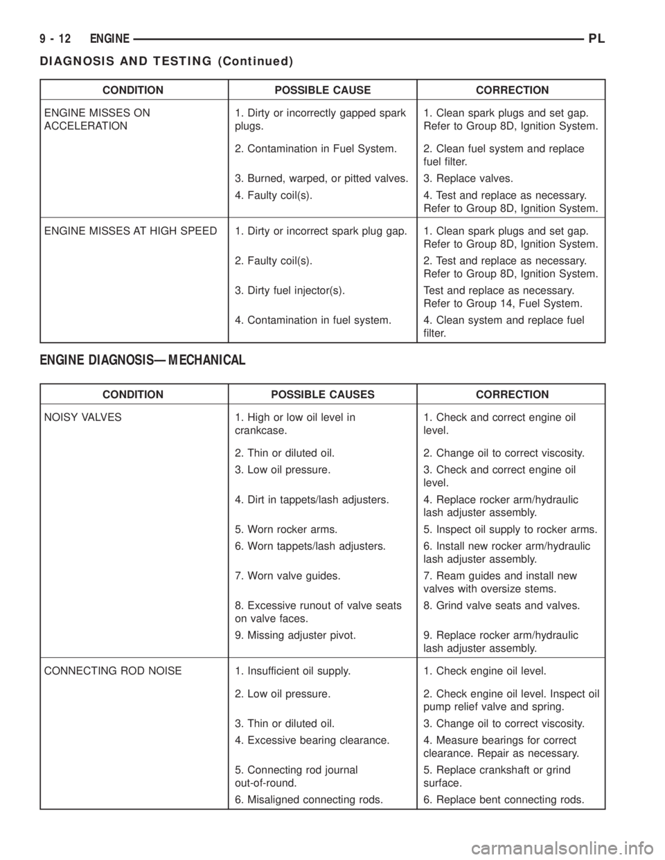
CONDITION POSSIBLE CAUSE CORRECTION
ENGINE MISSES ON
ACCELERATION1. Dirty or incorrectly gapped spark
plugs.1. Clean spark plugs and set gap.
Refer to Group 8D, Ignition System.
2. Contamination in Fuel System. 2. Clean fuel system and replace
fuel filter.
3. Burned, warped, or pitted valves. 3. Replace valves.
4. Faulty coil(s). 4. Test and replace as necessary.
Refer to Group 8D, Ignition System.
ENGINE MISSES AT HIGH SPEED 1. Dirty or incorrect spark plug gap. 1. Clean spark plugs and set gap.
Refer to Group 8D, Ignition System.
2. Faulty coil(s). 2. Test and replace as necessary.
Refer to Group 8D, Ignition System.
3. Dirty fuel injector(s). Test and replace as necessary.
Refer to Group 14, Fuel System.
4. Contamination in fuel system. 4. Clean system and replace fuel
filter.
ENGINE DIAGNOSISÐMECHANICAL
CONDITION POSSIBLE CAUSES CORRECTION
NOISY VALVES 1. High or low oil level in
crankcase.1. Check and correct engine oil
level.
2. Thin or diluted oil. 2. Change oil to correct viscosity.
3. Low oil pressure. 3. Check and correct engine oil
level.
4. Dirt in tappets/lash adjusters. 4. Replace rocker arm/hydraulic
lash adjuster assembly.
5. Worn rocker arms. 5. Inspect oil supply to rocker arms.
6. Worn tappets/lash adjusters. 6. Install new rocker arm/hydraulic
lash adjuster assembly.
7. Worn valve guides. 7. Ream guides and install new
valves with oversize stems.
8. Excessive runout of valve seats
on valve faces.8. Grind valve seats and valves.
9. Missing adjuster pivot. 9. Replace rocker arm/hydraulic
lash adjuster assembly.
CONNECTING ROD NOISE 1. Insufficient oil supply. 1. Check engine oil level.
2. Low oil pressure. 2. Check engine oil level. Inspect oil
pump relief valve and spring.
3. Thin or diluted oil. 3. Change oil to correct viscosity.
4. Excessive bearing clearance. 4. Measure bearings for correct
clearance. Repair as necessary.
5. Connecting rod journal
out-of-round.5. Replace crankshaft or grind
surface.
6. Misaligned connecting rods. 6. Replace bent connecting rods.
9 - 12 ENGINEPL
DIAGNOSIS AND TESTING (Continued)
Page 736 of 1285
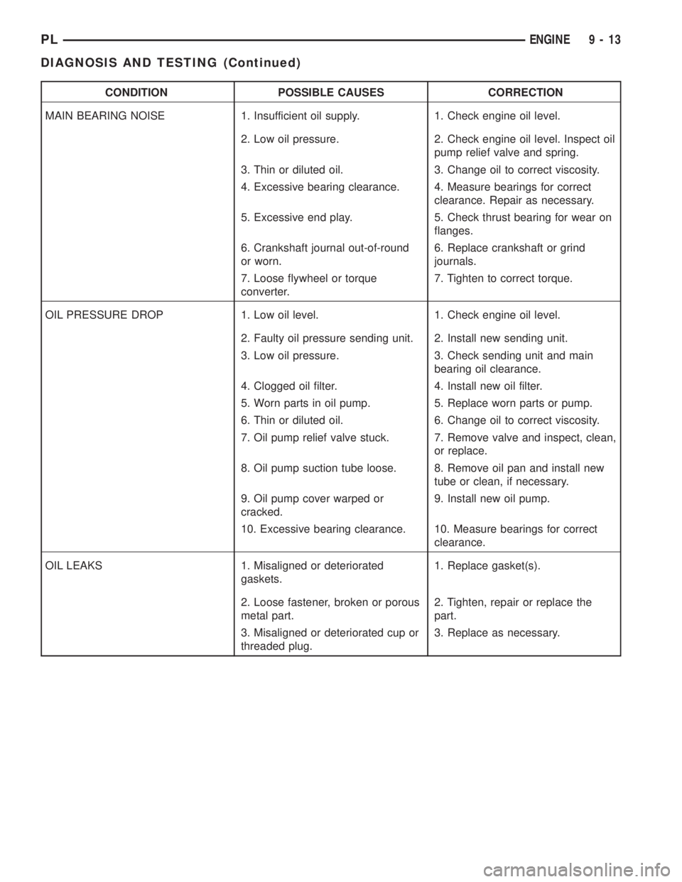
CONDITION POSSIBLE CAUSES CORRECTION
MAIN BEARING NOISE 1. Insufficient oil supply. 1. Check engine oil level.
2. Low oil pressure. 2. Check engine oil level. Inspect oil
pump relief valve and spring.
3. Thin or diluted oil. 3. Change oil to correct viscosity.
4. Excessive bearing clearance. 4. Measure bearings for correct
clearance. Repair as necessary.
5. Excessive end play. 5. Check thrust bearing for wear on
flanges.
6. Crankshaft journal out-of-round
or worn.6. Replace crankshaft or grind
journals.
7. Loose flywheel or torque
converter.7. Tighten to correct torque.
OIL PRESSURE DROP 1. Low oil level. 1. Check engine oil level.
2. Faulty oil pressure sending unit. 2. Install new sending unit.
3. Low oil pressure. 3. Check sending unit and main
bearing oil clearance.
4. Clogged oil filter. 4. Install new oil filter.
5. Worn parts in oil pump. 5. Replace worn parts or pump.
6. Thin or diluted oil. 6. Change oil to correct viscosity.
7. Oil pump relief valve stuck. 7. Remove valve and inspect, clean,
or replace.
8. Oil pump suction tube loose. 8. Remove oil pan and install new
tube or clean, if necessary.
9. Oil pump cover warped or
cracked.9. Install new oil pump.
10. Excessive bearing clearance. 10. Measure bearings for correct
clearance.
OIL LEAKS 1. Misaligned or deteriorated
gaskets.1. Replace gasket(s).
2. Loose fastener, broken or porous
metal part.2. Tighten, repair or replace the
part.
3. Misaligned or deteriorated cup or
threaded plug.3. Replace as necessary.
PLENGINE 9 - 13
DIAGNOSIS AND TESTING (Continued)
Page 741 of 1285
der head. The rocker shafts route oil to the rocker
arms/hydraulic lash adjuster assemblies.
SPLASH LUBRICATION
Oil returning to the pan from pressurized compo-
nents supplies lubrication to the valve stems. Cylin-
der bores and wrist pins are splash lubricated from
directed slots on the connecting rod thrust collars.
DIAGNOSIS AND TESTING
CHECKING ENGINE OIL PRESSURE
(1) Remove oil pressure switch and install gauge
assembly C-3292 with adaptor.
(2) Run engine until thermostat opens.
CAUTION: If oil pressure is 0 at idle, Do Not per-
form the 3000 RPM test in the next step.
(3) Oil Pressure:Curb Idle25 kPa (4 psi) mini-
mum3000 RPM170-550 kPa (25-80 psi).
(4) If oil pressure is 0 at idle. Shut off engine,
check for pressure relief valve stuck open, a clogged
oil pick-up screen or a damaged oil pick-up tube
O-ring.
SERVICE PROCEDURES
CYLINDER BORE AND PISTON SIZING
The cylinder walls should be checked for out-of-
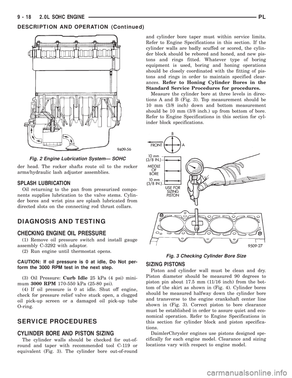
round and taper with recommended tool C-119 or
equivalent (Fig. 3). The cylinder bore out-of-roundand cylinder bore taper must within service limits.
Refer to Engine Specifications in this section. If the
cylinder walls are badly scuffed or scored, the cylin-
der block should be rebored and honed, and new pis-
tons and rings fitted. Whatever type of boring
equipment is used, boring and honing operations
should be closely coordinated with the fitting of pis-
tons and rings in order to maintain specified clear-
ances.Refer to Honing Cylinder Bores in the
Standard Service Procedures for procedures.
Measure the cylinder bore at three levels in direc-
tions A and B (Fig. 3). Top measurement should be
10 mm (3/8 inch) down and bottom measurement
should be 10 mm (3/8 inch.) up from bottom of bore.
Refer to Engine Specifications in this section for cyl-
inder block specifications.
SIZING PISTONS
Piston and cylinder wall must be clean and dry.
Piston diameter should be measured 90 degrees to
piston pin about 17.5 mm (11/16 inch) from the bot-
tom of the skirt as shown in (Fig. 4). Cylinder bores
should be measured halfway down the cylinder bore
and transverse to the engine crankshaft center line
shown in (Fig. 3). Correct piston to bore clearance
must be established in order to assure quiet and eco-
nomical operation. Refer to Engine Specifications in
this section for cylinder block and piston specifica-
tions.
DaimlerChrysler engines use pistons designed spe-
cifically for each engine model. Clearance and sizing
locations vary with respect to engine model.
Fig. 2 Engine Lubrication SystemÐ SOHC
Fig. 3 Checking Cylinder Bore Size
9 - 18 2.0L SOHC ENGINEPL
DESCRIPTION AND OPERATION (Continued)
Page 750 of 1285
(8) Install lower engine torque strut. Refer to pro-
cedure in this section.
(9) Connect exhaust system to manifold. Refer to
Group 11, Exhaust System for procedure and torque
specifications.
(10) Connect the downstream oxygen sensor.
(11) Install A/C compressor and hoses. Refer to
Group 24, Heater and Air Conditioning for procedure.
(12) Install accessory drive belts. Refer to Group 7,
Cooling System Accessory Drive Section for belt ten-
sion adjustment.
(13) Install inner splash shield.
(14) Install wheels and lower vehicle.
(15) Install power steering pump and reservoir.
Refer to Group 7, Cooling System Accessory Drive
Section for belt tension adjustment.
(16)Manual Transmission:Connect clutch cable,
reverse light electrical connector and shift linkages.
Refer to Group 6, Clutch.
(17)Automatic Transmission:Connect shifter,
kickdown linkage and cooler lines. Refer to Group 21,
Transaxle for procedures.
(18) Connect fuel line and heater hoses.
(19)
Install all ground straps. Connect engine wiring
harness. Refer to Group 8, Electrical for procedure.
(20) Install lower radiator hose, fan module, and
upper radiator hose. Refer to Group 7, Cooling Sys-
tem for procedures
(21) Fill cooling system. Refer to Group 7, Cooling
System for filling procedure.
(22) Install battery tray and battery.
(23) Install air cleaner housing assembly and con-
nect intake duct to intake manifold.(24) Connect all throttle body electrical connectors
and linkage.
(25) Install oil filter. Fill engine crankcase with
proper oil to correct level.
(26) Perform camshaft and crankshaft timing
relearn procedure as follows:
²Connect the DRB scan tool to the data link
(diagnostic) connector. This connector is located in
the passenger compartment; at the lower edge of
instrument panel; near the steering column.
²Turn the ignition switch on and access the ªmis-
cellaneousº screen.
²Select ªre-learn cam/crankº option and follow
directions on DRB screen.
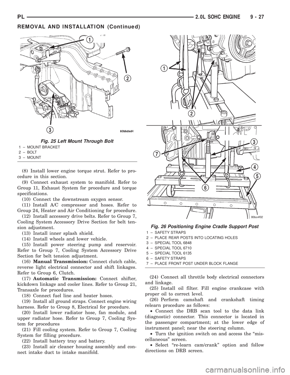
Fig. 25 Left Mount Through Bolt
1 ± MOUNT BRACKET
2 ± BOLT
3 ± MOUNT
Fig. 26 Positioning Engine Cradle Support Post
1 ± SAFETY STRAPS
2 ± PLACE REAR POSTS INTO LOCATING HOLES
3 ± SPECIAL TOOL 6848
4 ± SPECIAL TOOL 6710
5 ± SPECIAL TOOL 6135
6 ± SAFETY STRAPS
7 ± PLACE FRONT POST UNDER BLOCK FLANGE
PL2.0L SOHC ENGINE 9 - 27
REMOVAL AND INSTALLATION (Continued)
Page 771 of 1285
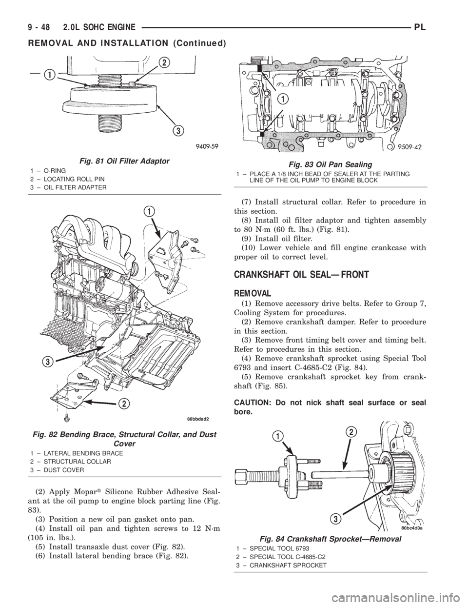
(2) Apply MopartSilicone Rubber Adhesive Seal-
ant at the oil pump to engine block parting line (Fig.
83).
(3) Position a new oil pan gasket onto pan.
(4) Install oil pan and tighten screws to 12 N´m
(105 in. lbs.).
(5) Install transaxle dust cover (Fig. 82).
(6) Install lateral bending brace (Fig. 82).(7) Install structural collar. Refer to procedure in
this section.
(8) Install oil filter adaptor and tighten assembly
to 80 N´m (60 ft. lbs.) (Fig. 81).
(9) Install oil filter.
(10) Lower vehicle and fill engine crankcase with
proper oil to correct level.
CRANKSHAFT OIL SEALÐFRONT
REMOVAL
(1) Remove accessory drive belts. Refer to Group 7,
Cooling System for procedures.
(2) Remove crankshaft damper. Refer to procedure
in this section.
(3) Remove front timing belt cover and timing belt.
Refer to procedures in this section.
(4) Remove crankshaft sprocket using Special Tool
6793 and insert C-4685-C2 (Fig. 84).
(5) Remove crankshaft sprocket key from crank-
shaft (Fig. 85).
CAUTION: Do not nick shaft seal surface or seal
bore.
Fig. 81 Oil Filter Adaptor
1 ± O-RING
2 ± LOCATING ROLL PIN
3 ± OIL FILTER ADAPTER
Fig. 82 Bending Brace, Structural Collar, and Dust
Cover
1 ± LATERAL BENDING BRACE
2 ± STRUCTURAL COLLAR
3 ± DUST COVER
Fig. 83 Oil Pan Sealing
1 ± PLACE A 1/8 INCH BEAD OF SEALER AT THE PARTING
LINE OF THE OIL PUMP TO ENGINE BLOCK
Fig. 84 Crankshaft SprocketÐRemoval
1 ± SPECIAL TOOL 6793
2 ± SPECIAL TOOL C-4685-C2
3 ± CRANKSHAFT SPROCKET
9 - 48 2.0L SOHC ENGINEPL
REMOVAL AND INSTALLATION (Continued)
Page 780 of 1285
(8) Install oil pick-up tube and oil pan.
(9) Install rear timing belt cover and camshaft
sprocket.
(10) Install timing belt tensioner, timing belt, and
front timing belt cover.
(11) Install crankshaft damper.
(12) Fill engine crankcase with proper oil to cor-
rect level.
(13) Connect negative cable to battery.
PISTON AND CONNECTING ROD
REMOVAL
(1) Remove cylinder head and oil pan. Refer to pro-
cedures in this section.
(2) Remove top ridge of cylinder bores with a reli-
able ridge reamer before removing pistons from cyl-
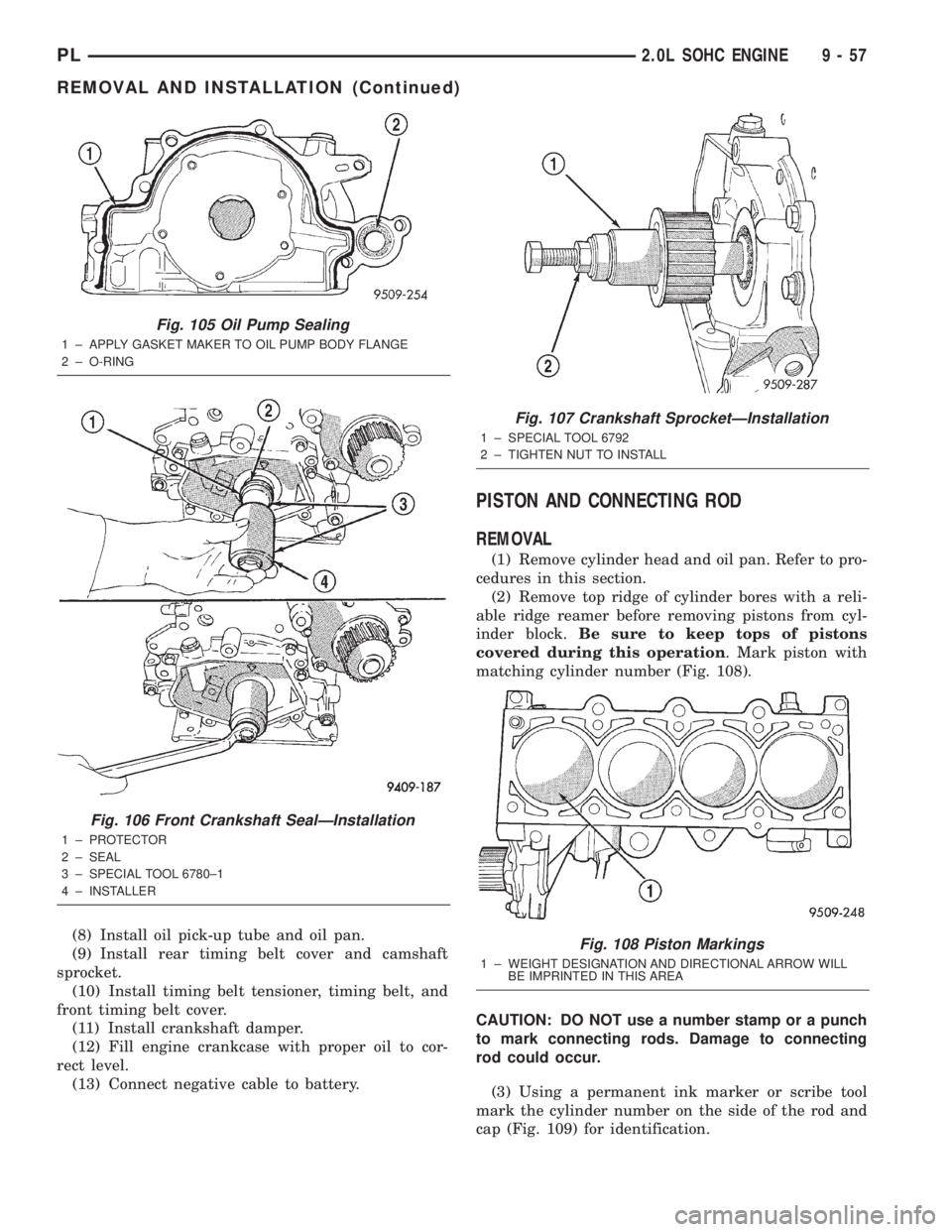
inder block.Be sure to keep tops of pistons
covered during this operation. Mark piston with
matching cylinder number (Fig. 108).
CAUTION: DO NOT use a number stamp or a punch
to mark connecting rods. Damage to connecting
rod could occur.
(3) Using a permanent ink marker or scribe tool
mark the cylinder number on the side of the rod and
cap (Fig. 109) for identification.
Fig. 105 Oil Pump Sealing
1 ± APPLY GASKET MAKER TO OIL PUMP BODY FLANGE
2 ± O-RING
Fig. 106 Front Crankshaft SealÐInstallation
1 ± PROTECTOR
2 ± SEAL
3 ± SPECIAL TOOL 6780±1
4 ± INSTALLER
Fig. 107 Crankshaft SprocketÐInstallation
1 ± SPECIAL TOOL 6792
2 ± TIGHTEN NUT TO INSTALL
Fig. 108 Piston Markings
1 ± WEIGHT DESIGNATION AND DIRECTIONAL ARROW WILL
BE IMPRINTED IN THIS AREA
PL2.0L SOHC ENGINE 9 - 57
REMOVAL AND INSTALLATION (Continued)
Page 801 of 1285
DIAGNOSIS AND TESTING
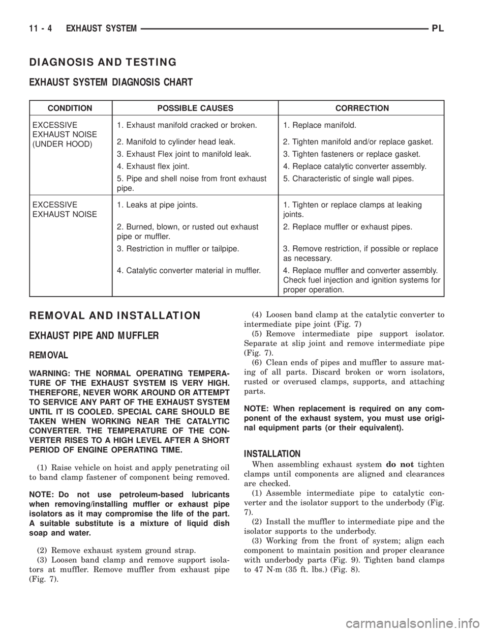
EXHAUST SYSTEM DIAGNOSIS CHART
CONDITION POSSIBLE CAUSES CORRECTION
EXCESSIVE
EXHAUST NOISE
(UNDER HOOD)1. Exhaust manifold cracked or broken. 1. Replace manifold.
2. Manifold to cylinder head leak. 2. Tighten manifold and/or replace gasket.
3. Exhaust Flex joint to manifold leak. 3. Tighten fasteners or replace gasket.
4. Exhaust flex joint. 4. Replace catalytic converter assembly.
5. Pipe and shell noise from front exhaust
pipe.5. Characteristic of single wall pipes.
EXCESSIVE
EXHAUST NOISE1. Leaks at pipe joints. 1. Tighten or replace clamps at leaking
joints.
2. Burned, blown, or rusted out exhaust
pipe or muffler.2. Replace muffler or exhaust pipes.
3. Restriction in muffler or tailpipe. 3. Remove restriction, if possible or replace
as necessary.
4. Catalytic converter material in muffler. 4. Replace muffler and converter assembly.
Check fuel injection and ignition systems for
proper operation.
REMOVAL AND INSTALLATION
EXHAUST PIPE AND MUFFLER
REMOVAL
WARNING: THE NORMAL OPERATING TEMPERA-
TURE OF THE EXHAUST SYSTEM IS VERY HIGH.
THEREFORE, NEVER WORK AROUND OR ATTEMPT
TO SERVICE ANY PART OF THE EXHAUST SYSTEM
UNTIL IT IS COOLED. SPECIAL CARE SHOULD BE
TAKEN WHEN WORKING NEAR THE CATALYTIC
CONVERTER. THE TEMPERATURE OF THE CON-
VERTER RISES TO A HIGH LEVEL AFTER A SHORT
PERIOD OF ENGINE OPERATING TIME.
(1) Raise vehicle on hoist and apply penetrating oil
to band clamp fastener of component being removed.
NOTE: Do not use petroleum-based lubricants
when removing/installing muffler or exhaust pipe
isolators as it may compromise the life of the part.
A suitable substitute is a mixture of liquid dish
soap and water.
(2) Remove exhaust system ground strap.
(3) Loosen band clamp and remove support isola-
tors at muffler. Remove muffler from exhaust pipe
(Fig. 7).(4) Loosen band clamp at the catalytic converter to
intermediate pipe joint (Fig. 7)
(5) Remove intermediate pipe support isolator.
Separate at slip joint and remove intermediate pipe
(Fig. 7).
(6) Clean ends of pipes and muffler to assure mat-
ing of all parts. Discard broken or worn isolators,
rusted or overused clamps, supports, and attaching
parts.
NOTE: When replacement is required on any com-
ponent of the exhaust system, you must use origi-
nal equipment parts (or their equivalent).
INSTALLATION
When assembling exhaust systemdo nottighten
clamps until components are aligned and clearances
are checked.
(1) Assemble intermediate pipe to catalytic con-
verter and the isolator support to the underbody (Fig.
7).
(2) Install the muffler to intermediate pipe and the
isolator supports to the underbody.
(3) Working from the front of system; align each
component to maintain position and proper clearance
with underbody parts (Fig. 9). Tighten band clamps
to 47 N´m (35 ft. lbs.) (Fig. 8).
11 - 4 EXHAUST SYSTEMPL