2000 DODGE NEON index
[x] Cancel search: indexPage 284 of 1285
HORN SWITCH
REMOVAL
(1) Disconnect and isolate the battery negative
cable (Fig. 5).
(2) Remove the Driver Airbag Module. Refer to
Group 8M Passive Restraint Systems, Driver Airbag
Module Removal and Installation.
(3) Clip off strap tie holding the horn switch wire
to the airbag module.
(4) Unclip horn switch wire connector from airbag
module.(5) Remove four torx screws from top side of air-
bag module.
(6) Fold airbag module cover down to expose the
horn switch.
(7) Lift the horn switch off indexing tabs and
remove from vehicle.
INSTALLATION
For installation, reverse the above procedures.
PLHORNS 8G - 5
REMOVAL AND INSTALLATION (Continued)
Page 360 of 1285
POWER DISTRIBUTION SYSTEMS
TABLE OF CONTENTS
page page
DESCRIPTION AND OPERATION
POWER DISTRIBUTION SYSTEM.............1
POWER DISTRIBUTION CENTER (PDC).......1
FUSE BLOCK.............................2REMOVAL AND INSTALLATION
FUSE BLOCK.............................2
POWER DISTRIBUTION CENTER (PDC).......2
DESCRIPTION AND OPERATION
POWER DISTRIBUTION SYSTEM
This group covers the various standard and
optional power distribution components used on this
model. Refer to the Component Index of Group 8W -
Wiring Diagrams for complete circuit diagrams of the
various power distribution components.
The power distribution system for this vehicle is
designed to provide safe, reliable, centralized and
convenient to access distribution of the electrical cur-
rent required to operate all of the many standard
and optional factory-installed electrical and electronic
powertrain, chassis, safety, comfort and convenience
systems. At the same time, these systems were
designed to provide centralized locations for conduct-
ing diagnosis of faulty circuits, and for sourcing the
additional current requirements of many aftermarket
vehicle accessory and convenience items.
These power distribution systems also incorporate
various types of circuit control and protection fea-
tures, including:
²Fuses
²Fuse cartridges
²Fusible links
²Automatic resetting circuit breakers
²Relays
²Flashers
²Timers
²Circuit splice blocks.
The power distribution system for this vehicle con-
sists of the following components:
²Power Distribution Center (PDC)
²Fuse Block
Following are general descriptions of the major
components in the power distribution system. Refer
to the owner's manual in the vehicle glove box for
more information on the features, use and operation
of all of the power distribution system components.
POWER DISTRIBUTION CENTER (PDC)
All of the electrical current distributed throughout
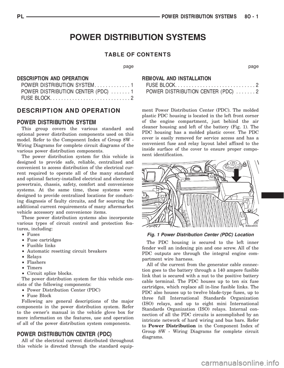
this vehicle is directed through the standard equip-ment Power Distribution Center (PDC). The molded
plastic PDC housing is located in the left front corner
of the engine compartment, just behind the air
cleaner housing and left of the battery (Fig. 1). The
PDC housing has a molded plastic cover. The PDC
cover is easily removed for service access and has a
convenient fuse and relay layout label affixed to the
inside surface of the cover to ensure proper compo-
nent identification.
The PDC housing is secured to the left inner
fender well an indexing pin and one screw. All of the
PDC outputs are through the integral engine com-
partment wire harness.
All of the current from the generator cable connec-
tion goes to the battery through a 140 ampere fusible
link that is secured with a nut to the positive battery
cable terminal. The PDC houses up to ten six fuse
cartridges, which replace all in-line fusible links. The
PDC also houses up to twelve blade-type fuses, up to
three full International Standards Organization
(ISO) relays, and up to eight mini International
Standards Organization (ISO) relays. Internal con-
nection of all the PDC circuits is accomplished by an
intricate network of hard wiring and bus bars. Refer
toPower Distributionin the Component Index of
Group 8W - Wiring Diagrams for complete circuit
diagrams.
Fig. 1 Power Distribution Center (PDC) Location
PLPOWER DISTRIBUTION SYSTEMS 8O - 1
Page 361 of 1285
The fusible link, fuses and relays are available for
service replacement. The PDC unit cannot be
repaired and is only serviced as a unit with the
engine compartment wire harness. If the PDC is
faulty or damaged, the engine compartment wire har-
ness assembly must be replaced.
FUSE BLOCK
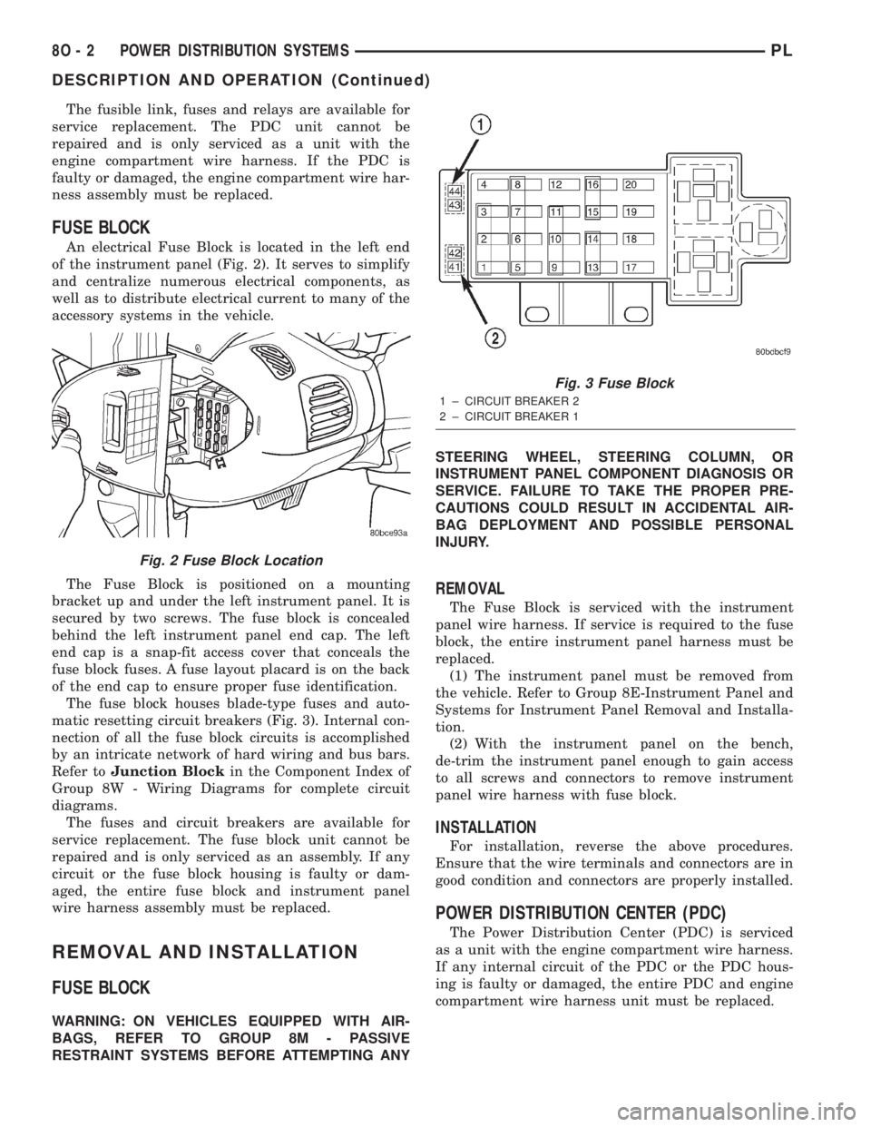
An electrical Fuse Block is located in the left end
of the instrument panel (Fig. 2). It serves to simplify
and centralize numerous electrical components, as
well as to distribute electrical current to many of the
accessory systems in the vehicle.
The Fuse Block is positioned on a mounting
bracket up and under the left instrument panel. It is
secured by two screws. The fuse block is concealed
behind the left instrument panel end cap. The left
end cap is a snap-fit access cover that conceals the
fuse block fuses. A fuse layout placard is on the back
of the end cap to ensure proper fuse identification.
The fuse block houses blade-type fuses and auto-
matic resetting circuit breakers (Fig. 3). Internal con-
nection of all the fuse block circuits is accomplished
by an intricate network of hard wiring and bus bars.
Refer toJunction Blockin the Component Index of
Group 8W - Wiring Diagrams for complete circuit
diagrams.
The fuses and circuit breakers are available for
service replacement. The fuse block unit cannot be
repaired and is only serviced as an assembly. If any
circuit or the fuse block housing is faulty or dam-
aged, the entire fuse block and instrument panel
wire harness assembly must be replaced.
REMOVAL AND INSTALLATION
FUSE BLOCK
WARNING: ON VEHICLES EQUIPPED WITH AIR-
BAGS, REFER TO GROUP 8M - PASSIVE
RESTRAINT SYSTEMS BEFORE ATTEMPTING ANYSTEERING WHEEL, STEERING COLUMN, OR
INSTRUMENT PANEL COMPONENT DIAGNOSIS OR
SERVICE. FAILURE TO TAKE THE PROPER PRE-
CAUTIONS COULD RESULT IN ACCIDENTAL AIR-
BAG DEPLOYMENT AND POSSIBLE PERSONAL
INJURY.
REMOVAL
The Fuse Block is serviced with the instrument
panel wire harness. If service is required to the fuse
block, the entire instrument panel harness must be
replaced.
(1) The instrument panel must be removed from
the vehicle. Refer to Group 8E-Instrument Panel and
Systems for Instrument Panel Removal and Installa-
tion.
(2) With the instrument panel on the bench,
de-trim the instrument panel enough to gain access
to all screws and connectors to remove instrument
panel wire harness with fuse block.
INSTALLATION
For installation, reverse the above procedures.
Ensure that the wire terminals and connectors are in
good condition and connectors are properly installed.
POWER DISTRIBUTION CENTER (PDC)
The Power Distribution Center (PDC) is serviced
as a unit with the engine compartment wire harness.
If any internal circuit of the PDC or the PDC hous-
ing is faulty or damaged, the entire PDC and engine
compartment wire harness unit must be replaced.
Fig. 2 Fuse Block Location
Fig. 3 Fuse Block
1 ± CIRCUIT BREAKER 2
2 ± CIRCUIT BREAKER 1
8O - 2 POWER DISTRIBUTION SYSTEMSPL
DESCRIPTION AND OPERATION (Continued)
Page 392 of 1285
WIRING DIAGRAMS
TABLE OF CONTENTS
page page
AIR CONDITIONING-HEATER........... 8W-42-1
AIRBAG SYSTEM.................... 8W-43-1
ANTI-LOCK BRAKES.................. 8W-35-1
AUDIO SYSTEM..................... 8W-47-1
CHARGING SYSTEM.................. 8W-20-1
COMPONENT INDEX.................. 8W-02-1
CONNECTOR PIN-OUTS............... 8W-80-1
CONNECTOR/GROUND LOCATIONS...... 8W-90-1
FRONT LIGHTING.................... 8W-50-1
FUEL/IGNITION SYSTEM.............. 8W-30-1
FUSE BLOCK........................ 8W-11-1
GENERAL INFORMATION.............. 8W-01-1
GROUND DISTRIBUTION.............. 8W-15-1
HORN/CIGAR LIGHTER/POWER OUTLET . . 8W-41-1
INSTRUMENT CLUSTER............... 8W-40-1INTERIOR LIGHTING.................. 8W-44-1
POWER DISTRIBUTION............... 8W-10-1
POWER DOOR LOCKS................ 8W-61-1
POWER MIRRORS................... 8W-62-1
POWER SUNROOF................... 8W-64-1
POWER WINDOWS................... 8W-60-1
REAR LIGHTING..................... 8W-51-1
REAR WINDOW DEFOGGER............ 8W-48-1
SPLICE INFORMATION................ 8W-70-1
SPLICE LOCATIONS.................. 8W-95-1
STARTING SYSTEM.................. 8W-21-1
TURN SIGNALS...................... 8W-52-1
VEHICLE THEFT SECURITY SYSTEM..... 8W-39-1
WIPERS............................ 8W-53-1
PLWIRING DIAGRAMS 8W - 1
Page 410 of 1285
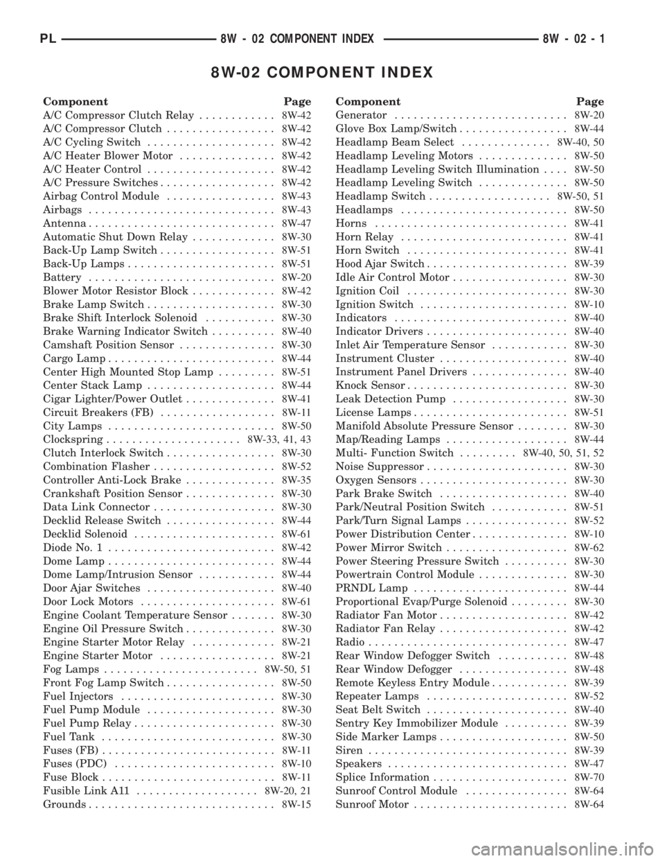
8W-02 COMPONENT INDEX
Component Page
A/C Compressor Clutch Relay............8W-42
A/C Compressor Clutch.................8W-42
A/C Cycling Switch....................8W-42
A/C Heater Blower Motor...............8W-42
A/C Heater Control....................8W-42
A/C Pressure Switches..................8W-42
Airbag Control Module.................8W-43
Airbags.............................8W-43
Antenna.............................8W-47
Automatic Shut Down Relay.............8W-30
Back-Up Lamp Switch..................8W-51
Back-Up Lamps.......................8W-51
Battery.............................8W-20
Blower Motor Resistor Block.............8W-42
Brake Lamp Switch....................8W-30
Brake Shift Interlock Solenoid...........8W-30
Brake Warning Indicator Switch..........8W-40
Camshaft Position Sensor...............8W-30
Cargo Lamp..........................8W-44
Center High Mounted Stop Lamp.........8W-51
Center Stack Lamp....................8W-44
Cigar Lighter/Power Outlet..............8W-41
Circuit Breakers (FB)..................8W-11
City Lamps..........................8W-50
Clockspring.....................8W-33, 41, 43
Clutch Interlock Switch.................8W-30
Combination Flasher...................8W-52
Controller Anti-Lock Brake..............8W-35
Crankshaft Position Sensor..............8W-30
Data Link Connector...................8W-30
Decklid Release Switch.................8W-44
Decklid Solenoid......................8W-61
Diode No. 1..........................8W-42
Dome Lamp..........................8W-44
Dome Lamp/Intrusion Sensor............8W-44
Door Ajar Switches....................8W-40
Door Lock Motors.....................8W-61
Engine Coolant Temperature Sensor.......8W-30
Engine Oil Pressure Switch..............8W-30
Engine Starter Motor Relay.............8W-21
Engine Starter Motor..................8W-21
Fog Lamps........................8W-50, 51
Front Fog Lamp Switch.................8W-50
Fuel Injectors........................8W-30
Fuel Pump Module....................8W-30
Fuel Pump Relay......................8W-30
Fuel Tank...........................8W-30
Fuses (FB)...........................8W-11
Fuses (PDC).........................8W-10
Fuse Block...........................8W-11
Fusible Link A11...................8W-20, 21
Grounds.............................8W-15Component Page
Generator...........................8W-20
Glove Box Lamp/Switch.................8W-44
Headlamp Beam Select..............8W-40, 50
Headlamp Leveling Motors..............8W-50
Headlamp Leveling Switch Illumination....8W-50
Headlamp Leveling Switch..............8W-50
Headlamp Switch...................8W-50, 51
Headlamps..........................8W-50
Horns..............................8W-41
Horn Relay..........................8W-41
Horn Switch.........................8W-41
Hood Ajar Switch......................8W-39
Idle Air Control Motor..................8W-30
Ignition Coil.........................8W-30
Ignition Switch.......................8W-10
Indicators...........................8W-40
Indicator Drivers......................8W-40
Inlet Air Temperature Sensor............8W-30
Instrument Cluster....................8W-40
Instrument Panel Drivers...............8W-40
Knock Sensor.........................8W-30
Leak Detection Pump..................8W-30
License Lamps........................8W-51
Manifold Absolute Pressure Sensor........8W-30
Map/Reading Lamps...................8W-44
Multi- Function Switch.........8W-40, 50, 51, 52
Noise Suppressor......................8W-30
Oxygen Sensors.......................8W-30
Park Brake Switch....................8W-40
Park/Neutral Position Switch............8W-51
Park/Turn Signal Lamps................8W-52
Power Distribution Center...............8W-10
Power Mirror Switch...................8W-62
Power Steering Pressure Switch..........8W-30
Powertrain Control Module..............8W-30
PRNDL Lamp........................8W-44
Proportional Evap/Purge Solenoid.........8W-30
Radiator Fan Motor....................8W-42
Radiator Fan Relay....................8W-42
Radio...............................8W-47
Rear Window Defogger Switch...........8W-48
Rear Window Defogger.................8W-48
Remote Keyless Entry Module............8W-39
Repeater Lamps......................8W-52
Seat Belt Switch......................8W-40
Sentry Key Immobilizer Module..........8W-39
Side Marker Lamps....................8W-50
Siren...............................8W-39
Speakers............................8W-47
Splice Information.....................8W-70
Sunroof Control Module................8W-64
Sunroof Motor........................8W-64
PL8W - 02 COMPONENT INDEX 8W - 02 - 1
Page 411 of 1285
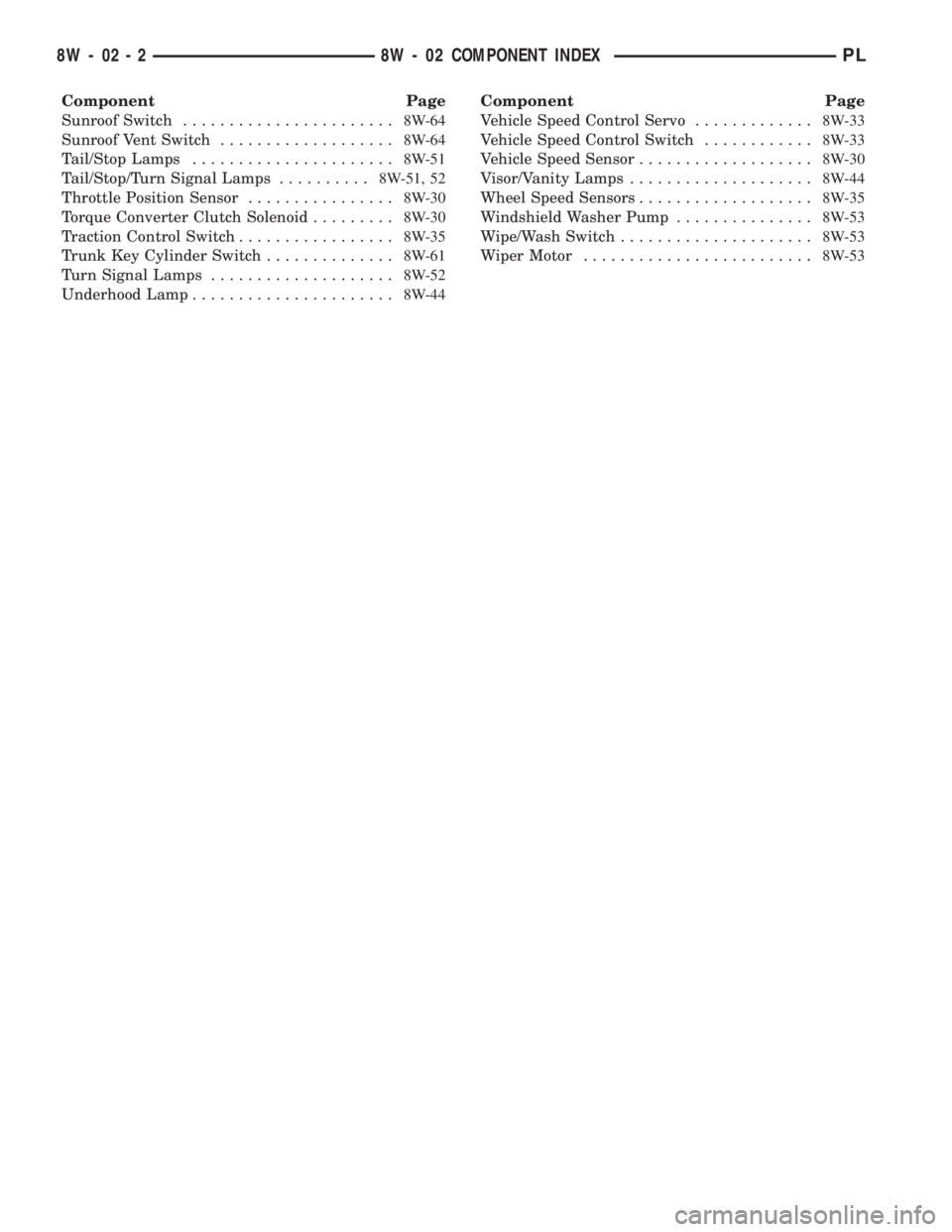
Component Page
Sunroof Switch.......................8W-64
Sunroof Vent Switch...................8W-64
Tail/Stop Lamps......................8W-51
Tail/Stop/Turn Signal Lamps..........8W-51, 52
Throttle Position Sensor................8W-30
Torque Converter Clutch Solenoid.........8W-30
Traction Control Switch.................8W-35
Trunk Key Cylinder Switch..............8W-61
Turn Signal Lamps....................8W-52
Underhood Lamp......................8W-44Component Page
Vehicle Speed Control Servo.............8W-33
Vehicle Speed Control Switch............8W-33
Vehicle Speed Sensor...................8W-30
Visor/Vanity Lamps....................8W-44
Wheel Speed Sensors...................8W-35
Windshield Washer Pump...............8W-53
Wipe/Wash Switch.....................8W-53
Wiper Motor.........................8W-53
8W - 02 - 2 8W - 02 COMPONENT INDEXPL
Page 658 of 1285
8W-90 CONNECTOR/GROUND LOCATIONS
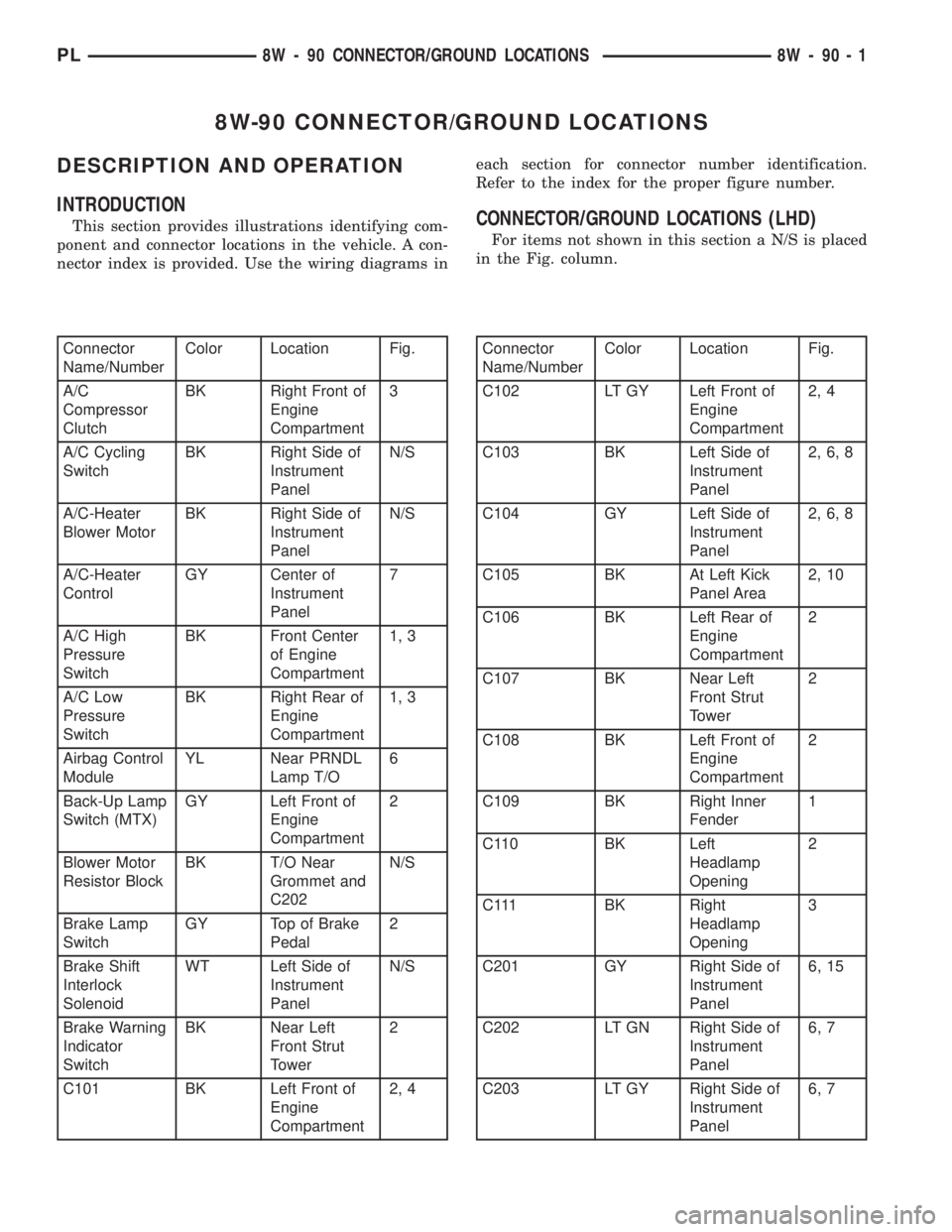
DESCRIPTION AND OPERATION
INTRODUCTION
This section provides illustrations identifying com-
ponent and connector locations in the vehicle. A con-
nector index is provided. Use the wiring diagrams ineach section for connector number identification.
Refer to the index for the proper figure number.CONNECTOR/GROUND LOCATIONS (LHD)
For items not shown in this section a N/S is placed
in the Fig. column.
Connector
Name/NumberColor Location Fig.
A/C
Compressor
ClutchBK Right Front of
Engine
Compartment3
A/C Cycling
SwitchBK Right Side of
Instrument
PanelN/S
A/C-Heater
Blower MotorBK Right Side of
Instrument
PanelN/S
A/C-Heater
ControlGY Center of
Instrument
Panel7
A/C High
Pressure
SwitchBK Front Center
of Engine
Compartment1, 3
A/C Low
Pressure
SwitchBK Right Rear of
Engine
Compartment1, 3
Airbag Control
ModuleYL Near PRNDL
Lamp T/O6
Back-Up Lamp
Switch (MTX)GY Left Front of
Engine
Compartment2
Blower Motor
Resistor BlockBK T/O Near
Grommet and
C202N/S
Brake Lamp
SwitchGY Top of Brake
Pedal2
Brake Shift
Interlock
SolenoidWT Left Side of
Instrument
PanelN/S
Brake Warning
Indicator
SwitchBK Near Left
Front Strut
Tower2
C101 BK Left Front of
Engine
Compartment2, 4Connector
Name/NumberColor Location Fig.
C102 LT GY Left Front of
Engine
Compartment2, 4
C103 BK Left Side of
Instrument
Panel2, 6, 8
C104 GY Left Side of
Instrument
Panel2, 6, 8
C105 BK At Left Kick
Panel Area2, 10
C106 BK Left Rear of
Engine
Compartment2
C107 BK Near Left
Front Strut
Tower2
C108 BK Left Front of
Engine
Compartment2
C109 BK Right Inner
Fender1
C110 BK Left
Headlamp
Opening2
C111 BK Right
Headlamp
Opening3
C201 GY Right Side of
Instrument
Panel6, 15
C202 LT GN Right Side of
Instrument
Panel6, 7
C203 LT GY Right Side of
Instrument
Panel6, 7
PL8W - 90 CONNECTOR/GROUND LOCATIONS 8W - 90 - 1
Page 698 of 1285
8W-95 SPLICE LOCATIONS
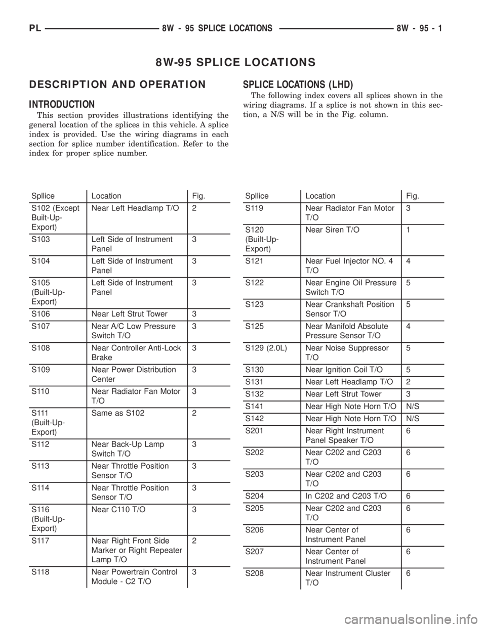
DESCRIPTION AND OPERATION
INTRODUCTION
This section provides illustrations identifying the
general location of the splices in this vehicle. A splice
index is provided. Use the wiring diagrams in each
section for splice number identification. Refer to the
index for proper splice number.
SPLICE LOCATIONS (LHD)
The following index covers all splices shown in the
wiring diagrams. If a splice is not shown in this sec-
tion, a N/S will be in the Fig. column.
Spllice Location Fig.
S102 (Except
Built-Up-
Export)Near Left Headlamp T/O 2
S103 Left Side of Instrument
Panel3
S104 Left Side of Instrument
Panel3
S105
(Built-Up-
Export)Left Side of Instrument
Panel3
S106 Near Left Strut Tower 3
S107 Near A/C Low Pressure
Switch T/O3
S108 Near Controller Anti-Lock
Brake3
S109 Near Power Distribution
Center3
S110 Near Radiator Fan Motor
T/O3
S 111
(Built-Up-
Export)Same as S102 2
S112 Near Back-Up Lamp
Switch T/O3
S113 Near Throttle Position
Sensor T/O3
S114 Near Throttle Position
Sensor T/O3
S116
(Built-Up-
Export)Near C110 T/O 3
S117 Near Right Front Side
Marker or Right Repeater
Lamp T/O2
S118 Near Powertrain Control
Module - C2 T/O3Spllice Location Fig.
S119 Near Radiator Fan Motor
T/O3
S120
(Built-Up-
Export)Near Siren T/O 1
S121 Near Fuel Injector NO. 4
T/O4
S122 Near Engine Oil Pressure
Switch T/O5
S123 Near Crankshaft Position
Sensor T/O5
S125 Near Manifold Absolute
Pressure Sensor T/O4
S129 (2.0L) Near Noise Suppressor
T/O5
S130 Near Ignition Coil T/O 5
S131 Near Left Headlamp T/O 2
S132 Near Left Strut Tower 3
S141 Near High Note Horn T/O N/S
S142 Near High Note Horn T/O N/S
S201 Near Right Instrument
Panel Speaker T/O6
S202 Near C202 and C203
T/O6
S203 Near C202 and C203
T/O6
S204 In C202 and C203 T/O 6
S205 Near C202 and C203
T/O6
S206 Near Center of
Instrument Panel6
S207 Near Center of
Instrument Panel6
S208 Near Instrument Cluster
T/O6
PL8W - 95 SPLICE LOCATIONS 8W - 95 - 1