Page 710 of 1285

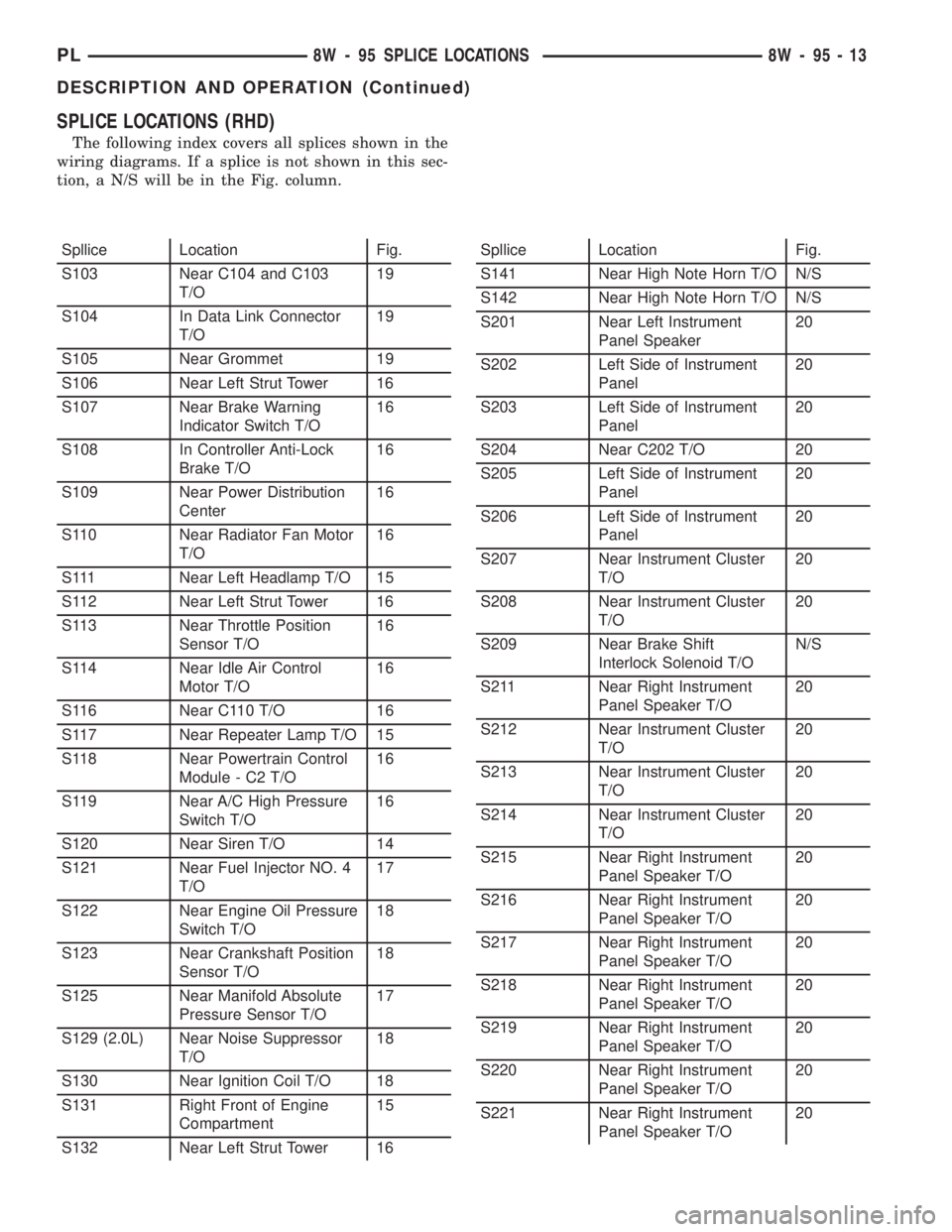
SPLICE LOCATIONS (RHD)
The following index covers all splices shown in the
wiring diagrams. If a splice is not shown in this sec-
tion, a N/S will be in the Fig. column.
Spllice Location Fig.
S103 Near C104 and C103
T/O19
S104 In Data Link Connector
T/O19
S105 Near Grommet 19
S106 Near Left Strut Tower 16
S107 Near Brake Warning
Indicator Switch T/O16
S108 In Controller Anti-Lock
Brake T/O16
S109 Near Power Distribution
Center16
S110 Near Radiator Fan Motor
T/O16
S111 Near Left Headlamp T/O 15
S112 Near Left Strut Tower 16
S113 Near Throttle Position
Sensor T/O16
S114 Near Idle Air Control
Motor T/O16
S116 Near C110 T/O 16
S117 Near Repeater Lamp T/O 15
S118 Near Powertrain Control
Module - C2 T/O16
S119 Near A/C High Pressure
Switch T/O16
S120 Near Siren T/O 14
S121 Near Fuel Injector NO. 4
T/O17
S122 Near Engine Oil Pressure
Switch T/O18
S123 Near Crankshaft Position
Sensor T/O18
S125 Near Manifold Absolute
Pressure Sensor T/O17
S129 (2.0L) Near Noise Suppressor
T/O18
S130 Near Ignition Coil T/O 18
S131 Right Front of Engine
Compartment15
S132 Near Left Strut Tower 16Spllice Location Fig.
S141 Near High Note Horn T/O N/S
S142 Near High Note Horn T/O N/S
S201 Near Left Instrument
Panel Speaker20
S202 Left Side of Instrument
Panel20
S203 Left Side of Instrument
Panel20
S204 Near C202 T/O 20
S205 Left Side of Instrument
Panel20
S206 Left Side of Instrument
Panel20
S207 Near Instrument Cluster
T/O20
S208 Near Instrument Cluster
T/O20
S209 Near Brake Shift
Interlock Solenoid T/ON/S
S211 Near Right Instrument
Panel Speaker T/O20
S212 Near Instrument Cluster
T/O20
S213 Near Instrument Cluster
T/O20
S214 Near Instrument Cluster
T/O20
S215 Near Right Instrument
Panel Speaker T/O20
S216 Near Right Instrument
Panel Speaker T/O20
S217 Near Right Instrument
Panel Speaker T/O20
S218 Near Right Instrument
Panel Speaker T/O20
S219 Near Right Instrument
Panel Speaker T/O20
S220 Near Right Instrument
Panel Speaker T/O20
S221 Near Right Instrument
Panel Speaker T/O20
PL8W - 95 SPLICE LOCATIONS 8W - 95 - 13
DESCRIPTION AND OPERATION (Continued)
Page 849 of 1285

BATTERY VOLTAGEÐPCM INPUT
OPERATION
In order for the PCM to operate, it must be sup-
plied with battery voltage and ground. The PCM
monitors the direct battery feed input to determine
battery charging rate and to control the injector ini-
tial opening point. It also has back-up RAM memory
used to store Diagnostic Trouble Codes (supply work-
ing DTCs). Direct battery feed is also used to perform
key-OFF diagnostics and to supply working voltage
to the controller for OBDII.
The five and eight volt regulators are protected
from shorts to ground. This protection allows diag-
nostics to be performed should the five volt power
supply become shorted to ground at any of the sen-
sors. A short to ground in the five volt power supply
will cause a ªno-startº situation. There is a Diagnos-
tic Trouble Code (DTC) if the five-volt power supply
becomes shorted to ground. Refer to the Diagnostic
Procedures Manual for more details on any on-board
diagnostic information.
If battery voltage is low the PCM will increase
injector pulse width (period of time that the injector
is energized).
The direct battery feed to the PCM is used as a
reference point to sense battery voltage.
Effect on Fuel Injectors
Fuel injectors are rated for operation at a specific
voltage. If the voltage increases, the plunger will
open faster and further (more efficient) and con-
versely, if voltage is low the injector will be slow to
open and will not open as far. Therefore, if sensed
battery voltage drops, the PCM increases injector
pulse-width to maintain the same volume of fuel
through the injector.
Charging
The PCM uses sensed battery voltage to verify that
target charging voltage (determined by Battery Tem-
perature Sensor) is being reached. To maintain the
target charging voltage, the PCM will full field the
generator to 0.5 volt above target then turn OFF to
0.5 volt below target. This will continue to occur up
to a 100 Hz frequency, 100 times per second.
BRAKE SWITCHÐPCM INPUT
OPERATION
When the brake switch is activated, the PCM
receives an input indicating that the brakes are
being applied. The brake switch is mounted on the
brake pedal support bracket.
CAMSHAFT POSITION SENSORÐPCM INPUT
DESCRIPTION
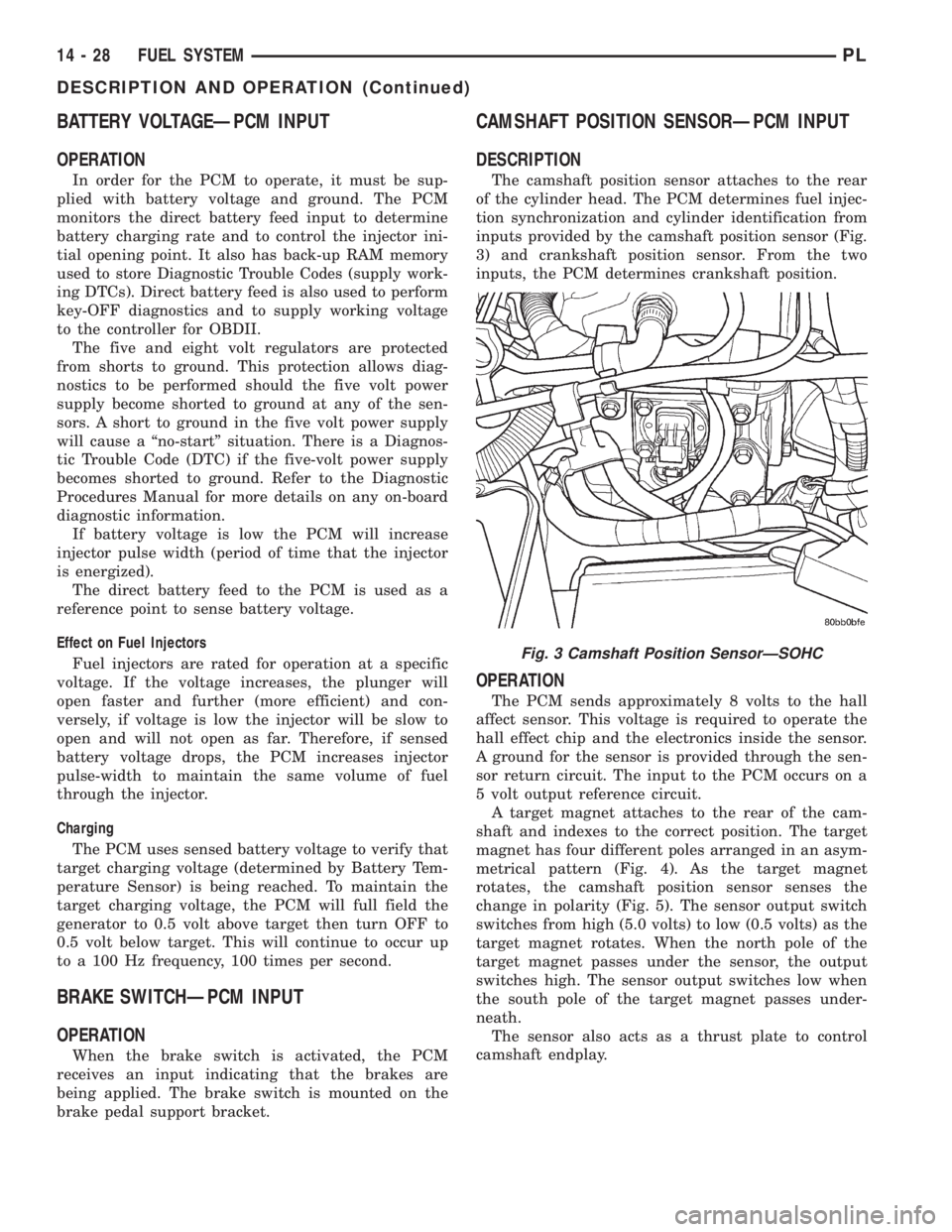
The camshaft position sensor attaches to the rear
of the cylinder head. The PCM determines fuel injec-
tion synchronization and cylinder identification from
inputs provided by the camshaft position sensor (Fig.
3) and crankshaft position sensor. From the two
inputs, the PCM determines crankshaft position.
OPERATION
The PCM sends approximately 8 volts to the hall
affect sensor. This voltage is required to operate the
hall effect chip and the electronics inside the sensor.
A ground for the sensor is provided through the sen-
sor return circuit. The input to the PCM occurs on a
5 volt output reference circuit.
A target magnet attaches to the rear of the cam-
shaft and indexes to the correct position. The target
magnet has four different poles arranged in an asym-
metrical pattern (Fig. 4). As the target magnet
rotates, the camshaft position sensor senses the
change in polarity (Fig. 5). The sensor output switch
switches from high (5.0 volts) to low (0.5 volts) as the
target magnet rotates. When the north pole of the
target magnet passes under the sensor, the output
switches high. The sensor output switches low when
the south pole of the target magnet passes under-
neath.
The sensor also acts as a thrust plate to control
camshaft endplay.
Fig. 3 Camshaft Position SensorÐSOHC
14 - 28 FUEL SYSTEMPL
DESCRIPTION AND OPERATION (Continued)
Page 1265 of 1285

INSTALLATION
For installation, reverse the above procedures.
DISASSEMBLY AND ASSEMBLY
HEATER-A/C HOUSING
Use this procedure if any or all of the following
items require service:
²Heater core
²Evaporator
²HVAC housing
The HVAC housing must be removed from the
vehicle before beginning with this procedure. Refer to
Unit Housing in this section for removal procedure.
DISASSEMBLY
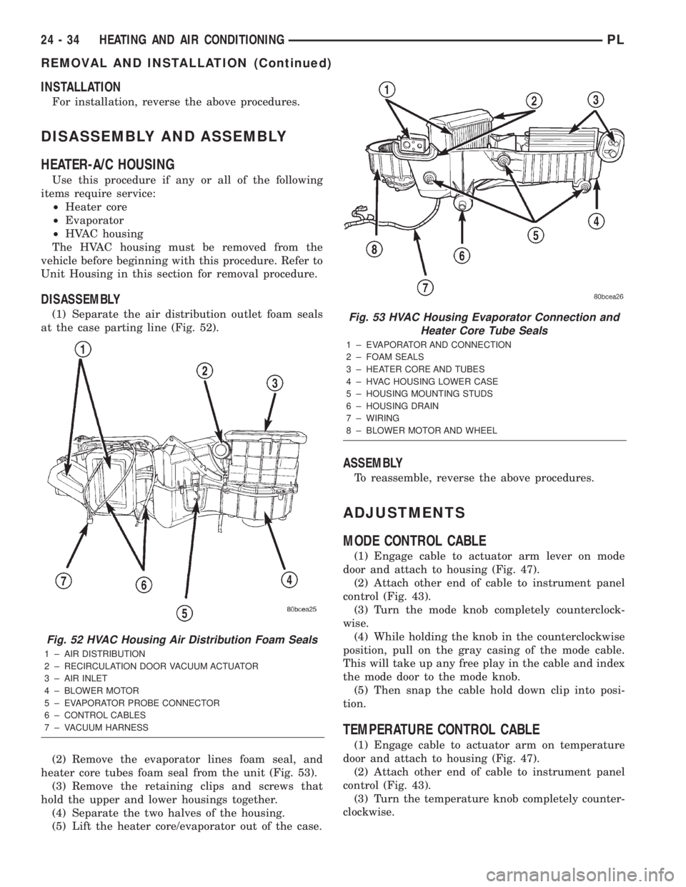
(1) Separate the air distribution outlet foam seals
at the case parting line (Fig. 52).
(2) Remove the evaporator lines foam seal, and
heater core tubes foam seal from the unit (Fig. 53).
(3) Remove the retaining clips and screws that
hold the upper and lower housings together.
(4) Separate the two halves of the housing.
(5) Lift the heater core/evaporator out of the case.
ASSEMBLY
To reassemble, reverse the above procedures.
ADJUSTMENTS
MODE CONTROL CABLE
(1) Engage cable to actuator arm lever on mode
door and attach to housing (Fig. 47).
(2) Attach other end of cable to instrument panel
control (Fig. 43).
(3) Turn the mode knob completely counterclock-
wise.
(4) While holding the knob in the counterclockwise
position, pull on the gray casing of the mode cable.
This will take up any free play in the cable and index
the mode door to the mode knob.
(5) Then snap the cable hold down clip into posi-
tion.
TEMPERATURE CONTROL CABLE
(1) Engage cable to actuator arm on temperature
door and attach to housing (Fig. 47).
(2) Attach other end of cable to instrument panel
control (Fig. 43).
(3) Turn the temperature knob completely counter-
clockwise.
Fig. 52 HVAC Housing Air Distribution Foam Seals
1 ± AIR DISTRIBUTION
2 ± RECIRCULATION DOOR VACUUM ACTUATOR
3 ± AIR INLET
4 ± BLOWER MOTOR
5 ± EVAPORATOR PROBE CONNECTOR
6 ± CONTROL CABLES
7 ± VACUUM HARNESS
Fig. 53 HVAC Housing Evaporator Connection and
Heater Core Tube Seals
1 ± EVAPORATOR AND CONNECTION
2 ± FOAM SEALS
3 ± HEATER CORE AND TUBES
4 ± HVAC HOUSING LOWER CASE
5 ± HOUSING MOUNTING STUDS
6 ± HOUSING DRAIN
7 ± WIRING
8 ± BLOWER MOTOR AND WHEEL
24 - 34 HEATING AND AIR CONDITIONINGPL
REMOVAL AND INSTALLATION (Continued)
Page 1266 of 1285
(4) While holding the knob in the counterclockwise
position, pull on the gray casing of the temperature
cable. This will take up any free play in the cable
and index the temperature door to the temperature
knob.(5) Then snap the cable hold down clip into posi-
tion.
(6) Remount control.
PLHEATING AND AIR CONDITIONING 24 - 35
ADJUSTMENTS (Continued)
Page:
< prev 1-8 9-16 17-24