2000 DODGE NEON stop start
[x] Cancel search: stop startPage 1091 of 1285
²Engine in closed loop
²Operating in Similar Conditions Window
²Short Term multiplied by Long Term less than
threshold
²Less than threshold for a predetermined time
If all of the previous criteria are met, the PCM will
count a good trip (three required) and turn off the
MIL.
Misfire Good Trip
If the following conditions are met the PCM will
count one good trip (three required) in order to turn
off the MIL:
²Operating in Similar Condition Window
²1000 engine revolutions with no misfire
Alternate Good Trip
Alternate Good Trips are used in place of Global
Good Trips for Comprehensive Components and
Major Monitors. If the Task Manager cannot run a
Global Good Trip because a component fault is stop-
ping the monitor from running, it will attempt to
count an Alternate Good Trip.
The Task Manager counts an Alternate Good Trip
for Comprehensive components when the following
conditions are met:
²Two minutes of engine run time
²No other faults occur
The Task Manager counts an Alternate Good Trip
for a Major Monitor when the monitor runs and
passes. Only the Major Monitor that failed needs to
pass to count an Alternate Good Trip.
Warm-Up Cycles
Once the MIL has been extinguished by the Good
Trip Counter, the PCM automatically switches to a
Warm-Up Cycle Counter that can be viewed on the
DRB III. Warm-Up Cycles are used to erase DTCs
and Freeze Frames. Forty Warm-Up cycles must
occur in order for the PCM to self-erase a DTC and
Freeze Frame. A Warm-Up Cycle is defined as fol-
lows:
²Engine coolant temperature must start below
and rise above 160É F
²Engine coolant temperature must rise by 40É F
²No further faults occur
Freeze Frame Data Storage
Once a failure occurs, the Task Manager records
several engine operating conditions and stores it in a
Freeze Frame. The Freeze Frame is considered one
frame of information taken by an on-board data
recorder. When a fault occurs, the PCM stores the
input data from various sensors so that technicians
can determine under what vehicle operating condi-
tions the failure occurred.
The data stored in Freeze Frame is usually
recorded when a system fails the first time for twotrip faults. Freeze Frame data will only be overwrit-
ten by a different fault with a higher priority.
CAUTION: Erasing DTCs, either with the DRB III or
by disconnecting the battery, also clears all Freeze
Frame data.
Similar Conditions Window
The Similar Conditions Window displays informa-
tion about engine operation during a monitor. Abso-
lute MAP (engine load) and Engine RPM are stored
in this window when a failure occurs. There are two
different Similar conditions Windows: Fuel System
and Misfire.
FUEL SYSTEM
²Fuel System Similar Conditions WindowÐ
An indicator that 'Absolute MAP When Fuel Sys Fail'
and 'RPM When Fuel Sys Failed' are all in the same
range when the failure occurred. Indicated by switch-
ing from 'NO' to 'YES'.
²Absolute MAP When Fuel Sys FailÐ The
stored MAP reading at the time of failure. Informs
the user at what engine load the failure occurred.
²Absolute MAPÐ A live reading of engine load
to aid the user in accessing the Similar Conditions
Window.
²RPM When Fuel Sys FailÐ The stored RPM
reading at the time of failure. Informs the user at
what engine RPM the failure occurred.
²Engine RPMÐ A live reading of engine RPM
to aid the user in accessing the Similar Conditions
Window.
²Adaptive Memory FactorÐ The PCM uti-
lizes both Short Term Compensation and Long Term
Adaptive to calculate the Adaptive Memory Factor
for total fuel correction.
²Upstream O2S VoltsÐ A live reading of the
Oxygen Sensor to indicate its performance. For
example, stuck lean, stuck rich, etc.
²SCW Time in Window (Similar Conditions
Window Time in Window)Ð A timer used by the
PCM that indicates that, after all Similar Conditions
have been met, if there has been enough good engine
running time in the SCW without failure detected.
This timer is used to increment a Good Trip.
²Fuel System Good Trip CounterÐATrip
Counter used to turn OFF the MIL for Fuel System
DTCs. To increment a Fuel System Good Trip, the
engine must be in the Similar Conditions Window,
Adaptive Memory Factor must be less than cali-
brated threshold and the Adaptive Memory Factor
must stay below that threshold for a calibrated
amount of time.
²Test Done This TripÐ Indicates that the
monitor has already been run and completed during
the current trip.
25 - 4 EMISSION CONTROL SYSTEMSPL
DESCRIPTION AND OPERATION (Continued)
Page 1103 of 1285
²200 revolution increments for immediate cata-
lyst damage
²1000 revolution increments for emissions viola-
tion and Inspection/Maintenance (I/M) test failure
NOTE: The percent of misfire for malfunction crite-
ria varies due to RPM and load. As the engine
speed increases or load decreases, the effects of a
misfire diminishes due to crankshaft momentum.
Failure percentages also vary from engine to
engine.
Monitor OperationÐThe PCM utilizes the
Crankshaft Speed Fluctuation method to monitor for
misfire. The misfire monitor utilizes a crankshaft
position sensor to determine engine RPM. The sensor
can detect slight variations in engine speed due to
misfire. Misfire is continuously monitored once the
enabling conditions are met.
Once enabling conditions are met, the PCM counts
the number of misfires in every 200 revolutions of
the crankshaft. If, duringfive200 counters, the mis-
fire percentage exceeds a predetermined value, a
maturing code is set and a Freeze Frame is entered.
Freeze Frame data is recorded during the last 200
revolutions of the 1000 revolution period. A failure on
the second consecutive trip matures the code and a
DTC is set.
If misfire continues during the initial trip, the MIL
is not illuminated. However, the MIL flashes when
the misfire percentage exceeds the malfunction per-
centage, in any 200 revolution period, that would
cause permanent catalyst damage. This is a one trip
monitor. If misfire reaches a point in which catalyst
damage is likely to occur, the MIL flashes and a DTC
is stored in a Freeze Frame. The engine defaults to
open loop operation to prevent increased fuel flow to
the cylinders. Once misfire is below the predeter-
mined percentage, the MIL stops flashing but
remains illuminated.
The 1000 revolution counters are two trip moni-
tors. As with the fuel system monitor, Freeze Frame
data is from the original fault, and MIL extinguish-
ing requires the monitor to pass under similar condi-
tions.
The Adaptive NumeratorÐThe Misfire Monitor
takes into account component wear, sensor fatigue
and machining tolerances. The PCM compares the
crankshaft in the vehicle to data on an ideal crank
and uses this as a basis to determine variance. To do
this, the crankshaft sensor monitors the reference
notches in the crank. The PCM uses the first signal
set as a point of reference. It then measures where
the second set of signals is, compared to where engi-
neering data has determined it should be. This vari-
ance is the Adaptive Numerator. The monitor will not
run if the numerator is not set.If the Adaptive Numerator is equal to the default
value, the adaptive Numerator has not been learned
and the Misfire Monitor does not run. If the Adaptive
Numerator exceeds its limits, the PCM sets a DTC
for Adaptive Numerator and illuminates the MIL.
RPM ErrorÐThe PCM also checks the machining
tolerances for each group of slots. By monitoring the
speed of the crank from the first slot to the last slot
in a group, the PCM can calculate engine RPM. The
variance between groups of slots is know as the RPM
error. In order for the PCM to run the Misfire Mon-
itor, RPM error must be less than approximately 5%.
Enabling ConditionsÐThe following conditions
must be met before the PCM runs the Misfire Moni-
tor:
²RPM
²Engine Coolant Temperature (ECT)
²Barometric Pressure (MAP)
²Fuel level
²Ambient air Temperature
Pending ConditionsÐThe Misfire Monitor does
not run when the MIL is illuminated for any of the
following:
²Limp in mode for
Ð MAP
Ð TPS
Ð Crankshaft Sensor
Ð Engine Coolant Temperature Sensor
²Speed Sensor DTC
²EGR Electrical
²EVAP Electrical
²Idle Speed Faults
²Intake Air Temperature
²Oxygen Sensor Monitor
²Oxygen Sensor Electrical
Conflict ConditionsÐIf any of the following con-
ditions conflict with the Misfire Monitor, the monitor
will not run:
²Low fuel level
²MAP voltage rapidly changing
²Severe engine decel
²TPS toggling OPEN/CLOSED
²Engine RPM too low (RPM levels by vehicle)
²Engine RPM too high (RPM levels vary by vehi-
cle)
²Full Lean or Decel Fuel Shut-off
²Cold start
FUEL SYSTEM MONITOR
To comply with clean air regulations, vehicles are
equipped with catalytic converters. These converters
reduce the emission of hydrocarbons, oxides of nitro-
gen and carbon monoxide. The catalyst works best
when the air fuel (A/F) ratio is at or near the opti-
mum of 14.7 to 1.
25 - 16 EMISSION CONTROL SYSTEMSPL
DESCRIPTION AND OPERATION (Continued)
Page 1105 of 1285
Immediately after a cold start, between predeter-
mined temperature thresholds limits, the three port
solenoid is briefly energized. This initializes the
pump by drawing air into the pump cavity and also
closes the vent seal. During non test conditions the
vent seal is held open by the pump diaphragm
assembly which pushes it open at the full travel posi-
tion. The vent seal will remain closed while the
pump is cycling due to the reed switch triggering of
the three port solenoid that prevents the diaphragm
assembly from reaching full travel. After the brief
initialization period, the solenoid is de-energized
allowing atmospheric pressure to enter the pump
cavity, thus permitting the spring to drive the dia-
phragm which forces air out of the pump cavity and
into the vent system. When the solenoid is energized
and de energized, the cycle is repeated creating flow
in typical diaphragm pump fashion. The pump is con-
trolled in 2 modes:
Pump Mode:The pump is cycled at a fixed rate to
achieve a rapid pressure build in order to shorten the
overall test length.
Test Mode:The solenoid is energized with a fixed
duration pulse. Subsequent fixed pulses occur when
the diaphragm reaches the Switch closure point.
The spring in the pump is set so that the system
will achieve an equalized pressure of about 7.5º H20.
The cycle rate of pump strokes is quite rapid as the
system begins to pump up to this pressure. As the
pressure increases, the cycle rate starts to drop off. If
there is no leak in the system, the pump would even-
tually stop pumping at the equalized pressure. If
there is a leak, it will continue to pump at a rate rep-
resentative of the flow characteristic of the size of the
leak. From this information we can determine if the
leak is larger than the required detection limit (cur-
rently set at.040º orifice by CARB). If a leak is
revealed during the leak test portion of the test, the
test is terminated at the end of the test mode and no
further system checks will be performed.
After passing the leak detection phase of the test,
system pressure is maintained by turning on the
LDP's solenoid until the purge system is activated.
Purge activation in effect creates a leak. The cycle
rate is again interrogated and when it increases due
to the flow through the purge system, the leak check
portion of the diagnostic is complete.
The canister vent valve will unseal the system
after completion of the test sequence as the pump
diaphragm assembly moves to the full travel position.
Evaporative system functionality will be verified by
using the stricter evap purge flow monitor. At an
appropriate warm idle the LDP will be energized to
seal the canister vent. The purge flow will be clocked
up from some small value in an attempt to see a
shift in the 02 control system. If fuel vapor, indicatedby a shift in the 02 control, is present the test is
passed. If not, it is assumed that the purge system is
not functioning in some respect. The LDP is again
turned off and the test is ended.
Enabling Conditions for Systems with LDP
²Ambient Air Temperature
²Barometric Pressure
²Fuel level
²Engine Temperature
²No stalling
²Battery voltage
NON-LDP VEHICLESÐOn a vehicle without an
EVAP leak detection pump system, changes in short
term memory and movement in target IAC at idle or
idle speed change, are used to monitor the system.
There are two stages for this test.
Stage OneÐStage one is a non-intrusive test.
The PCM compares adaptive memory values between
purge and purge-free cells. The PCM uses these val-
ues to determine the amount of fuel vapors entering
the system. If the difference between the cells
exceeds a predetermined value, the test passes. If
not, then the monitor advances to state two.
Stage TwoÐOnce the enabling conditions are
met, the PCM de-energizes the Duty Cycle Purge
(DCP) solenoid. The PCM then waits until engine
RPM, Short Term Compensation and Idle Air Control
have all stabilized. Once stable, the PCM increments
the DCP solenoid cycle rate approximately 6% every
8 engine revolutions. If during the test any one of
three conditions occur before the DCP cycle reaches
100%, the EVAP system is considered to be opera-
tional and the test passes. These conditions are as
follows:
²RPM rises by a predetermined amount
²Short Term drops by a predetermined amount
²Idle Air Control closes by a predetermined
amount
When none of the previous conditions occur, the
test fails and the PCM increments a counter by one.
When the PCM runs the test three times during a
trip, and the counter has been incremented to three,
the monitor fails and a Freeze Frame is stored.
Enabling Conditions (Stage Two)ÐThe follow-
ing conditions must be met to enable the EVAP Mon-
itor (without LDP)
²Ambient Air Temperature
²Barometric Pressure
²Fuel level
²Engine Temperature
²Engine run time
²RPM stable
²MAP
²Generator, radiator fans, A/C clutch
Pending Conditions-With or Without LDPÐ
The EVAP Monitor is suspended and does not run,
25 - 18 EMISSION CONTROL SYSTEMSPL
DESCRIPTION AND OPERATION (Continued)
Page 1135 of 1285
DIAGNOSIS AND TESTING
WATER LEAKS
Water leaks can be caused by poor sealing,
improper body component alignment, body seam
porosity, missing plugs, or blocked drain holes. Cen-
trifugal and gravitational force can cause water to
drip from a location away from the actual leak point,
making leak detection difficult. All body sealing
points should be water tight in normal wet-driving
conditions. Water flowing downward from the front of
the vehicle should not enter the passenger or luggage
compartment. Moving sealing surfaces will not
always seal water tight under all conditions. At
times, side glass or door seals will allow water to
enter the passenger compartment during high pres-
sure washing or hard driving rain (severe) condi-
tions. Overcompensating on door or glass
adjustments to stop a water leak that occurs under
severe conditions can cause premature seal wear and
excessive closing or latching effort. After completing
a repair, water-test vehicle to verify leak has stopped
before returning vehicle to use.
VISUAL INSPECTION BEFORE WATER LEAK TESTS
Verify that floor and body plugs are in place, body
drains are clear, and body components are properly
aligned and sealed. If component alignment or seal-
ing is necessary, refer to the appropriate section of
this group for proper procedures.
WATER LEAK TESTS
WARNING: DO NOT USE ELECTRIC SHOP LIGHTS
OR TOOLS IN WATER TEST AREA. PERSONAL
INJURY CAN RESULT.
When the conditions causing a water leak have
been determined, simulate the conditions as closely
as possible.
²If a leak occurs with the vehicle parked in a
steady light rain, flood the leak area with an open-
ended garden hose.
²If a leak occurs while driving at highway speeds
in a steady rain, test the leak area with a reasonable
velocity stream or fan spray of water. Direct the
spray in a direction comparable to actual conditions.
²If a leak occurs when the vehicle is parked on an
incline, hoist the end or side of the vehicle to simu-
late this condition. This method can be used when
the leak occurs when the vehicle accelerates, stops or
turns. If the leak occurs on acceleration, hoist the
front of the vehicle. If the leak occurs when braking,
hoist the back of the vehicle. If the leak occurs on left
turns, hoist the left side of the vehicle. If the leak
occurs on right turns, hoist the right side of the vehi-cle. For hoisting recommendations refer to Group 0,
Lubrication and Maintenance, General Information
section.
WATER LEAK DETECTION
To detect a water leak point-of-entry, do a water
test and watch for water tracks or droplets forming
on the inside of the vehicle. If necessary, remove inte-
rior trim covers or panels to gain visual access to the
leak area. If the hose cannot be positioned without
being held, have someone help do the water test.
Some water leaks must be tested for a considerable
length of time to become apparent. When a leak
appears, find the lowest point of the water track or
drop. After leak point has been found, repair the leak
and water test to verify that the leak has stopped.
Locating the entry point of water that is leaking
into a cavity between panels can be difficult. The
trapped water may splash or run from the cavity,
often at a distance from the entry point. Most water
leaks of this type become apparent after accelerating,
stopping, turning, or when on an incline.
MIRROR INSPECTION METHOD
When a leak point area is visually obstructed, use
a suitable mirror to gain visual access. A mirror can
also be used to deflect light to a limited-access area
to assist in locating a leak point.
BRIGHT LIGHT LEAK TEST METHOD
Some water leaks in the luggage compartment can
be detected without water testing. Position the vehi-
cle in a brightly lit area. From inside the darkened
luggage compartment inspect around seals and body
seams. If necessary, have a helper direct a drop light
over the suspected leak areas around the luggage
compartment. If light is visible through a normally
sealed location, water could enter through the open-
ing.
PRESSURIZED LEAK TEST METHOD
When a water leak into the passenger compart-
ment cannot be detected by water testing, pressurize
the passenger compartment and soap test exterior of
the vehicle. To pressurize the passenger compart-
ment, close all doors and windows, start engine, and
set heater control to high blower in HEAT position. If
engine can not be started, connect a charger to the
battery to ensure adequate voltage to the blower.
With interior pressurized, apply dish detergent solu-
tion to suspected leak area on the exterior of the
vehicle. Apply detergent solution with spray device or
soft bristle brush. If soap bubbles occur at a body
seam, joint, seal or gasket, the leak entry point could
be at that location.
23 - 18 BODYPL
Page 1244 of 1285
WARNING: PROTECT SKIN AND EYES FROM CON-
TACTING CO2 PERSONAL INJURY CAN RESULT.
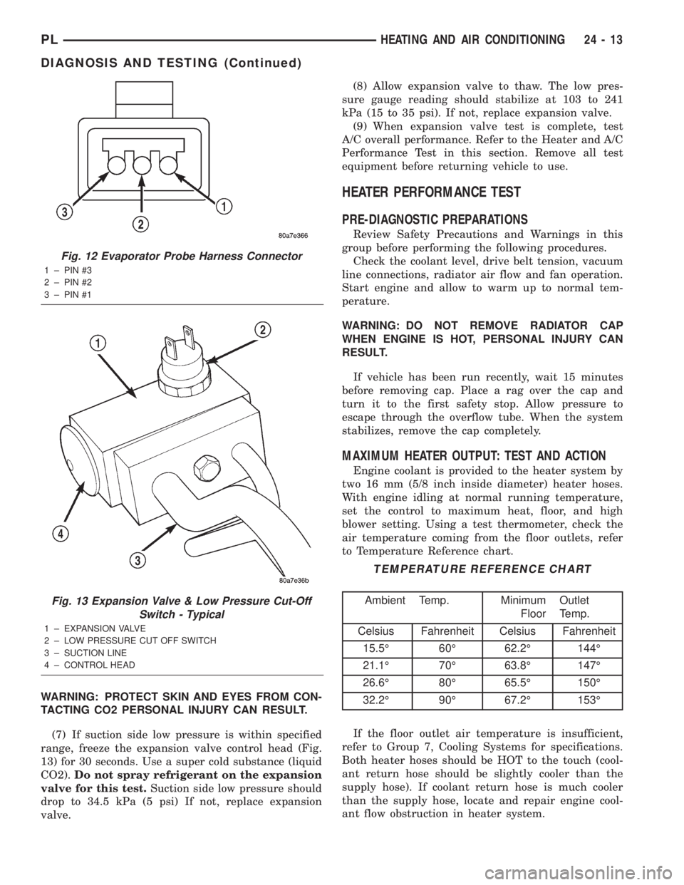
(7) If suction side low pressure is within specified
range, freeze the expansion valve control head (Fig.
13) for 30 seconds. Use a super cold substance (liquid
CO2).Do not spray refrigerant on the expansion
valve for this test.Suction side low pressure should
drop to 34.5 kPa (5 psi) If not, replace expansion
valve.(8) Allow expansion valve to thaw. The low pres-
sure gauge reading should stabilize at 103 to 241
kPa (15 to 35 psi). If not, replace expansion valve.
(9) When expansion valve test is complete, test
A/C overall performance. Refer to the Heater and A/C
Performance Test in this section. Remove all test
equipment before returning vehicle to use.
HEATER PERFORMANCE TEST
PRE-DIAGNOSTIC PREPARATIONS
Review Safety Precautions and Warnings in this
group before performing the following procedures.
Check the coolant level, drive belt tension, vacuum
line connections, radiator air flow and fan operation.
Start engine and allow to warm up to normal tem-
perature.
WARNING: DO NOT REMOVE RADIATOR CAP
WHEN ENGINE IS HOT, PERSONAL INJURY CAN
RESULT.
If vehicle has been run recently, wait 15 minutes
before removing cap. Place a rag over the cap and
turn it to the first safety stop. Allow pressure to
escape through the overflow tube. When the system
stabilizes, remove the cap completely.
MAXIMUM HEATER OUTPUT: TEST AND ACTION
Engine coolant is provided to the heater system by
two 16 mm (5/8 inch inside diameter) heater hoses.
With engine idling at normal running temperature,
set the control to maximum heat, floor, and high
blower setting. Using a test thermometer, check the
air temperature coming from the floor outlets, refer
to Temperature Reference chart.
If the floor outlet air temperature is insufficient,
refer to Group 7, Cooling Systems for specifications.
Both heater hoses should be HOT to the touch (cool-
ant return hose should be slightly cooler than the
supply hose). If coolant return hose is much cooler
than the supply hose, locate and repair engine cool-
ant flow obstruction in heater system.
Fig. 12 Evaporator Probe Harness Connector
1 ± PIN #3
2 ± PIN #2
3 ± PIN #1
Fig. 13 Expansion Valve & Low Pressure Cut-Off
Switch - Typical
1 ± EXPANSION VALVE
2 ± LOW PRESSURE CUT OFF SWITCH
3 ± SUCTION LINE
4 ± CONTROL HEAD
TEMPERATURE REFERENCE CHART
Ambient Temp. Minimum
FloorOutlet
Temp.
Celsius Fahrenheit Celsius Fahrenheit
15.5É 60É 62.2É 144É
21.1É 70É 63.8É 147É
26.6É 80É 65.5É 150É
32.2É 90É 67.2É 153É
PLHEATING AND AIR CONDITIONING 24 - 13
DIAGNOSIS AND TESTING (Continued)
Page 1249 of 1285
CAUTION: Do not overcharge refrigerant system,
as excessive compressor head pressure can cause
noise and system failure.
After the system has been tested for leaks and
evacuated, a refrigerant (R-134a) charge can be
injected into the system.
NOTE: When connecting the service equipment
coupling to the line fitting, verify that the valve of
the coupling is fully closed. This will reduce the
amount of effort required to make the connection.
(1) If using a separate vacuum pump close all
valves before disconnecting pump. Connect manifold
gauge set to the A/C service ports (Fig. 16).
NOTE: The air conditioning system in this vehicle
holds (27 oz. or 1.69 lbs.) of R-134a refrigerant.
(2) Measure refrigerant (refer to capacities). Refer
to the instructions provided with the equipment
being used.
(3) Verify engine is shut off. Open the suction and
discharge valves. Open the charge valve to allow the
refrigerant to flow into the system. When the trans-
fer of refrigerant has stopped, close the suction and
discharge valve.
(4) If all of the charge did not transfer from the
dispensing device, put vehicle controls into the fol-
lowing mode:
²Automatic transaxle in park or manual tran-
saxle in neutral
²Engine idling at 700 rpm
²A/C control set in 100 percent outside air
²Panel mode
²Blower motor ON high speed
²Vehicle windows closed
If the A/C compressor does not engage, test the
compressor clutch control circuit and correct any fail-
ure. Refer to Group 8W, Wiring Diagrams.
(5) Open the suction valve to allow the remaining
refrigerant to transfer to the system.
WARNING: TAKE CARE NOT TO OPEN THE DIS-
CHARGE (HIGH-PRESSURE) VALVE AT THIS TIME.
(6) Close all valves and test the A/C system perfor-
mance.
(7) Disconnect the charging station or manifold
gauge set. Install the service port caps.
EVACUATING REFRIGERANT SYSTEM
NOTE: Special effort must be used to prevent mois-
ture from entering the A/C system oil. Moisture in
the oil is very difficult to remove and will cause a
reliability problem with the compressor.If a compressor designed to use R-134a refrigerant
is left open to the atmosphere for an extended period
of time. It is recommended that the refrigerant oil be
drained and replaced with new oil or a new compres-
sor be used. This will eliminate the possibility of con-
taminating the refrigerant system.
If the refrigerant system has been open to the
atmosphere, it must be evacuated before the system
can be filled. Moisture and air mixed with the refrig-
erant will raise the compressor head pressure above
acceptable operating levels. This will reduce the per-
formance of the air conditioner and damage the com-
pressor. Moisture will boil at near room temperature
when exposed to vacuum. To evacuate the refrigerant
system:
NOTE: When connecting the service equipment
coupling to the line fitting, verify that the valve of
the coupling is fully closed. This will reduce the
amount of effort required to make the connection.
(1) Connect a suitable charging station, refrigerant
recovery machine, and a manifold gauge set with
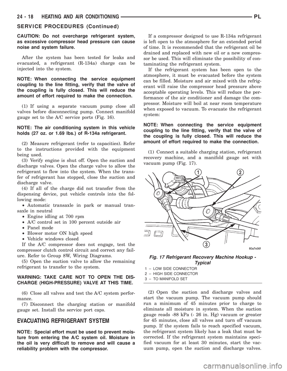
vacuum pump (Fig. 17).
(2) Open the suction and discharge valves and
start the vacuum pump. The vacuum pump should
run a minimum of 45 minutes prior to charge to
eliminate all moisture in system. When the suction
gauge reads -88 kPa (- 26 in. Hg) vacuum or greater
for 45 minutes, close all valves and turn off vacuum
pump. If the system fails to reach specified vacuum,
the refrigerant system likely has a leak that must be
corrected. If the refrigerant system maintains speci-
fied vacuum for at least 30 minutes, start the vac-
uum pump, open the suction and discharge valves.
Fig. 17 Refrigerant Recovery Machine Hookup -
Typical
1 ± LOW SIDE CONNECTOR
2 ± HIGH SIDE CONNECTOR
3 ± TO MANIFOLD SET
24 - 18 HEATING AND AIR CONDITIONINGPL
SERVICE PROCEDURES (Continued)