2000 DODGE NEON instrument panel
[x] Cancel search: instrument panelPage 359 of 1285
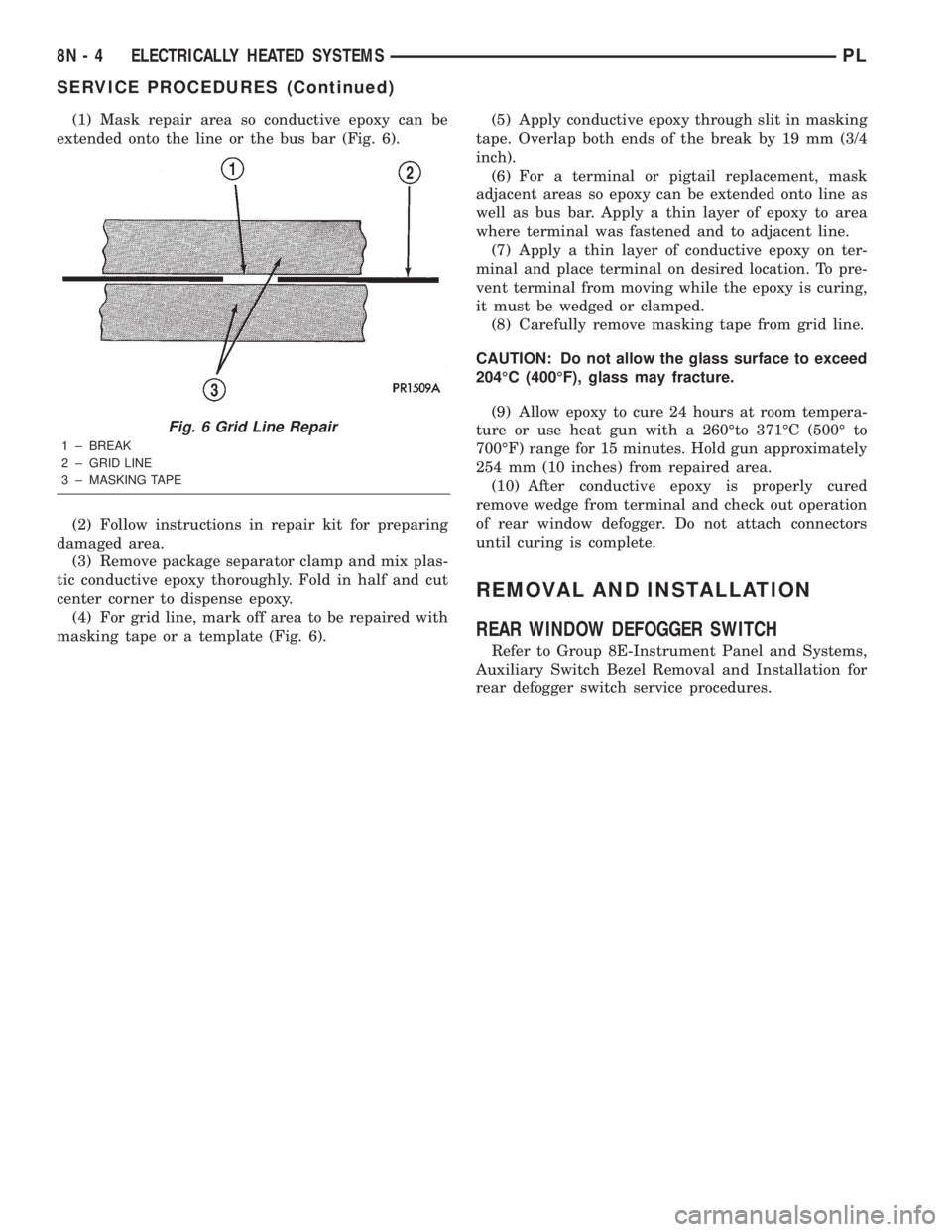
(1) Mask repair area so conductive epoxy can be
extended onto the line or the bus bar (Fig. 6).
(2) Follow instructions in repair kit for preparing
damaged area.
(3) Remove package separator clamp and mix plas-
tic conductive epoxy thoroughly. Fold in half and cut
center corner to dispense epoxy.
(4) For grid line, mark off area to be repaired with
masking tape or a template (Fig. 6).(5) Apply conductive epoxy through slit in masking
tape. Overlap both ends of the break by 19 mm (3/4
inch).
(6) For a terminal or pigtail replacement, mask
adjacent areas so epoxy can be extended onto line as
well as bus bar. Apply a thin layer of epoxy to area
where terminal was fastened and to adjacent line.
(7) Apply a thin layer of conductive epoxy on ter-
minal and place terminal on desired location. To pre-
vent terminal from moving while the epoxy is curing,
it must be wedged or clamped.
(8) Carefully remove masking tape from grid line.
CAUTION: Do not allow the glass surface to exceed
204ÉC (400ÉF), glass may fracture.
(9) Allow epoxy to cure 24 hours at room tempera-
ture or use heat gun with a 260Éto 371ÉC (500É to
700ÉF) range for 15 minutes. Hold gun approximately
254 mm (10 inches) from repaired area.
(10) After conductive epoxy is properly cured
remove wedge from terminal and check out operation
of rear window defogger. Do not attach connectors
until curing is complete.
REMOVAL AND INSTALLATION
REAR WINDOW DEFOGGER SWITCH
Refer to Group 8E-Instrument Panel and Systems,
Auxiliary Switch Bezel Removal and Installation for
rear defogger switch service procedures.
Fig. 6 Grid Line Repair
1 ± BREAK
2 ± GRID LINE
3 ± MASKING TAPE
8N - 4 ELECTRICALLY HEATED SYSTEMSPL
SERVICE PROCEDURES (Continued)
Page 361 of 1285
The fusible link, fuses and relays are available for
service replacement. The PDC unit cannot be
repaired and is only serviced as a unit with the
engine compartment wire harness. If the PDC is
faulty or damaged, the engine compartment wire har-
ness assembly must be replaced.
FUSE BLOCK
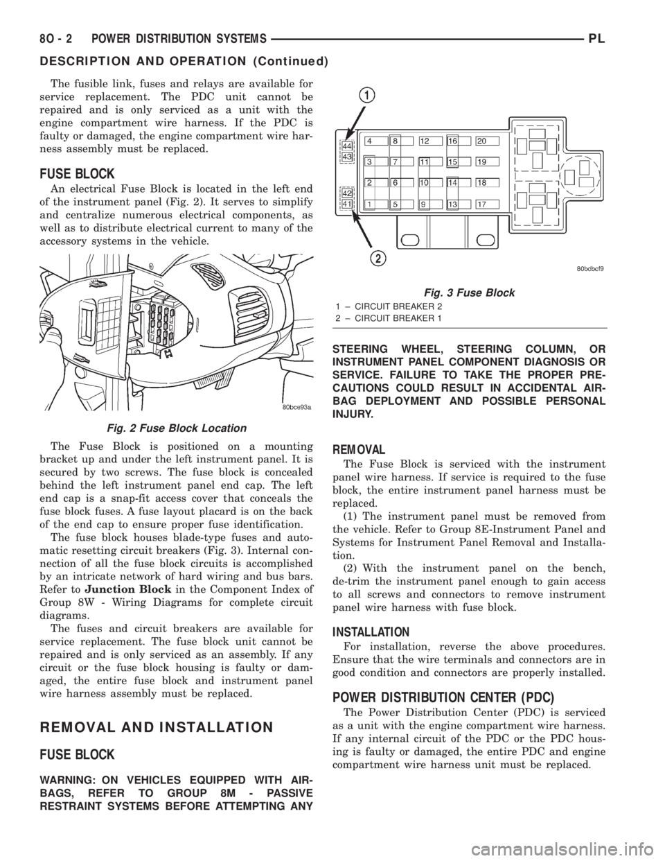
An electrical Fuse Block is located in the left end
of the instrument panel (Fig. 2). It serves to simplify
and centralize numerous electrical components, as
well as to distribute electrical current to many of the
accessory systems in the vehicle.
The Fuse Block is positioned on a mounting
bracket up and under the left instrument panel. It is
secured by two screws. The fuse block is concealed
behind the left instrument panel end cap. The left
end cap is a snap-fit access cover that conceals the
fuse block fuses. A fuse layout placard is on the back
of the end cap to ensure proper fuse identification.
The fuse block houses blade-type fuses and auto-
matic resetting circuit breakers (Fig. 3). Internal con-
nection of all the fuse block circuits is accomplished
by an intricate network of hard wiring and bus bars.
Refer toJunction Blockin the Component Index of
Group 8W - Wiring Diagrams for complete circuit
diagrams.
The fuses and circuit breakers are available for
service replacement. The fuse block unit cannot be
repaired and is only serviced as an assembly. If any
circuit or the fuse block housing is faulty or dam-
aged, the entire fuse block and instrument panel
wire harness assembly must be replaced.
REMOVAL AND INSTALLATION
FUSE BLOCK
WARNING: ON VEHICLES EQUIPPED WITH AIR-
BAGS, REFER TO GROUP 8M - PASSIVE
RESTRAINT SYSTEMS BEFORE ATTEMPTING ANYSTEERING WHEEL, STEERING COLUMN, OR
INSTRUMENT PANEL COMPONENT DIAGNOSIS OR
SERVICE. FAILURE TO TAKE THE PROPER PRE-
CAUTIONS COULD RESULT IN ACCIDENTAL AIR-
BAG DEPLOYMENT AND POSSIBLE PERSONAL
INJURY.
REMOVAL
The Fuse Block is serviced with the instrument
panel wire harness. If service is required to the fuse
block, the entire instrument panel harness must be
replaced.
(1) The instrument panel must be removed from
the vehicle. Refer to Group 8E-Instrument Panel and
Systems for Instrument Panel Removal and Installa-
tion.
(2) With the instrument panel on the bench,
de-trim the instrument panel enough to gain access
to all screws and connectors to remove instrument
panel wire harness with fuse block.
INSTALLATION
For installation, reverse the above procedures.
Ensure that the wire terminals and connectors are in
good condition and connectors are properly installed.
POWER DISTRIBUTION CENTER (PDC)
The Power Distribution Center (PDC) is serviced
as a unit with the engine compartment wire harness.
If any internal circuit of the PDC or the PDC hous-
ing is faulty or damaged, the entire PDC and engine
compartment wire harness unit must be replaced.
Fig. 2 Fuse Block Location
Fig. 3 Fuse Block
1 ± CIRCUIT BREAKER 2
2 ± CIRCUIT BREAKER 1
8O - 2 POWER DISTRIBUTION SYSTEMSPL
DESCRIPTION AND OPERATION (Continued)
Page 369 of 1285
(1) With the ignition switch in RUN position, press
and hold the transmitter Unlock button (Fig. 1) for a
minimum of 4 seconds to a maximum of 10 seconds.
(2) Within the 4-10 second range, depress the
transmitter Lock button (Fig. 1). A chime will be
heard to indicate a successful toggle, at which time
the buttons may be released.
SWITCHING OPERATING MODES/
CONFIGURING A NEW MODULE
Refer to Group 8Q-Vehicle Theft/Security Systems,
Switching Operating Modes/Configuring A New Mod-
ule under Service Procedures.
TRANSMITTER PROGRAMMING
The Remote Keyless Entry transmitters can be
programmed with the use of the DRB IIItscan tool
or by the customer.
DRB lllTPROGRAMMING
When using the DRB IIItscan tool, select:
(1) ªTheft Alarmº
(2) ªVTSSº
(3) ªMiscellaneousº
and then the desired function.
CUSTOMER PROGRAMMING
For a customer to be able to program RKE trans-
mitters themselves, at least one RKE transmitter
must be programmed already. This procedure is to
add additional transmitters. If all transmitters are
lost, the DRB IIItscan tool must be used to program
the new transmitters.
(1) With the ignition switch in RUN position, press
and hold the transmitter Unlock button (Fig. 1) for a
minimum of 4 seconds to a maximum of 10 seconds.
(2) Within the 4-10 second range, depress the
transmitter Lock button (Fig. 1). A chime will be
heard to indicate successful toggle, at which time the
buttons may be released.
(3) Turn the ignition switch off to exist transmitter
programming mode.
REMOVAL AND INSTALLATION
DECK LID RELEASE SOLENOID
REMOVAL
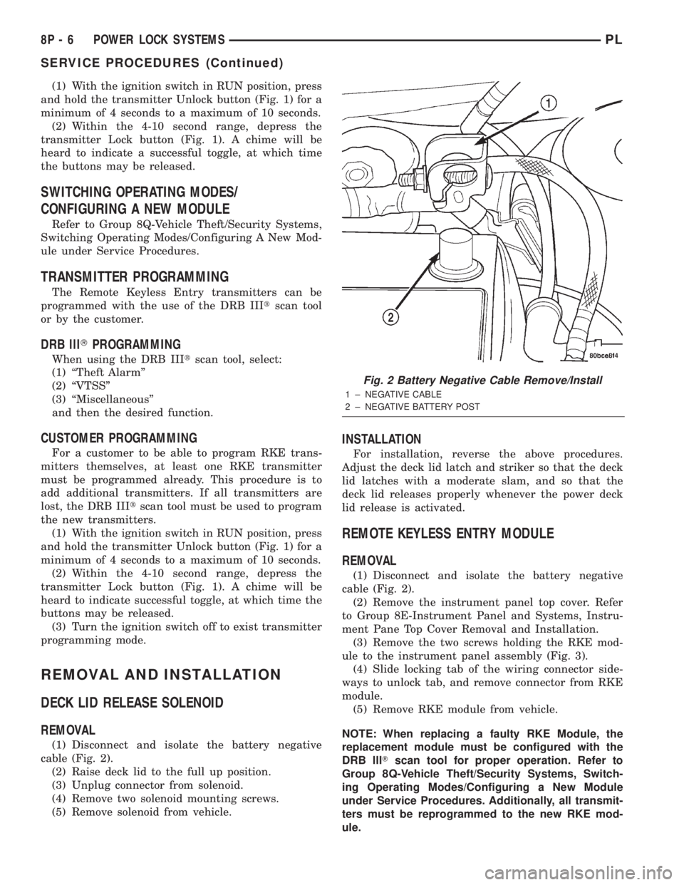
(1) Disconnect and isolate the battery negative
cable (Fig. 2).
(2) Raise deck lid to the full up position.
(3) Unplug connector from solenoid.
(4) Remove two solenoid mounting screws.
(5) Remove solenoid from vehicle.
INSTALLATION
For installation, reverse the above procedures.
Adjust the deck lid latch and striker so that the deck
lid latches with a moderate slam, and so that the
deck lid releases properly whenever the power deck
lid release is activated.
REMOTE KEYLESS ENTRY MODULE
REMOVAL
(1) Disconnect and isolate the battery negative
cable (Fig. 2).
(2) Remove the instrument panel top cover. Refer
to Group 8E-Instrument Panel and Systems, Instru-
ment Pane Top Cover Removal and Installation.
(3) Remove the two screws holding the RKE mod-
ule to the instrument panel assembly (Fig. 3).
(4) Slide locking tab of the wiring connector side-
ways to unlock tab, and remove connector from RKE
module.
(5) Remove RKE module from vehicle.
NOTE: When replacing a faulty RKE Module, the
replacement module must be configured with the
DRB lllTscan tool for proper operation. Refer to
Group 8Q-Vehicle Theft/Security Systems, Switch-
ing Operating Modes/Configuring a New Module
under Service Procedures. Additionally, all transmit-
ters must be reprogrammed to the new RKE mod-
ule.
Fig. 2 Battery Negative Cable Remove/Install
1 ± NEGATIVE CABLE
2 ± NEGATIVE BATTERY POST
8P - 6 POWER LOCK SYSTEMSPL
SERVICE PROCEDURES (Continued)
Page 375 of 1285
memory to determine whether a valid key is in the
ignition lock cylinder.
The Sentry Key transponder cannot be repaired
and, if faulty or damaged, it must be replaced.
SENTRY KEY IMMOBILIZER SYSTEM
INDICATOR LAMP
The Sentry Key Immobilizer System (SKIS) uses
the Vehicle Theft Security System (VTSS) indicator
LED to give an indication when the SKIS is faulty or
when the vehicle has been immobilized due to the
use of an invalid ignition key. The LED is controlled
by the instrument cluster circuitry based upon mes-
sages received from the Sentry Key Immobilizer
Module (SKIM) through the Body Control Module
(BCM) on the Programmable Communication Inter-
face (PCI) bus.
The SKIM sends messages to the instrument clus-
ter, via the BCM, to turn the LED on for about three
seconds when the ignition switch is turned to the ON
position as a bulb test. After completion of the bulb
test, the SKIM sends PCI bus messages to keep the
LED off for a duration of about one second. Then the
SKIM sends messages to the instrument cluster cir-
cuitry to turn the LED on or off based upon the
results of the SKIS self-tests. If the VTSS indicator
LED comes on and stays on after the bulb test, it
indicates that the SKIM has detected a system mal-
function and/or that the SKIS has become inopera-
tive. If the SKIM detects an invalid key when the
ignition switch is turned to the ON position, it sends
messages to the instrument cluster to flash the VTSS
indicator LED.
The SKIM can also send messages to the instru-
ment cluster to flash the LED and to generate a sin-
gle audible chime tone. These functions serve as an
indication to the customer that the SKIS has been
placed in its ªCustomer Learnº programming mode.
See Sentry Key Immobilizer System Transponder
Programming in this group for more information on
the ªCustomer Learnº programming mode.
The VTSS indicator LED uses a replaceable Light
Emitting Diode (LED) on the instrument cluster elec-
tronic circuit board. Refer to Group 8E - Instrument
Panel Systems for Cluster Lamp Removal and Instal-
lation. If the VTSS indicator LED comes on and
stays on after the bulb test function, diagnosis of the
SKIS should be performed with a DRB IIItscan tool
and the proper Body Diagnostic Procedures Manual.
TRIGGERING THE VTSS
After the VTSS is armed, any of the following will
trigger the system:
²Opening any door.
²Opening the hood.
²Removing the trunk lock cylinder.²Turning the ignition to the RUN/START position
with an invalid Sentry Key.
NOTE: The ignition switch can be turned to the
accessory position without triggering the alarm sys-
tem.
DIAGNOSIS AND TESTING
SENTRY KEY IMMOBILIZER SYSTEM
WARNING: ON VEHICLES EQUIPPED WITH AIR-
BAGS, REFER TO GROUP 8M - PASSIVE
RESTRAINT SYSTEMS BEFORE ATTEMPTING ANY
STEERING WHEEL, STEERING COLUMN, OR
INSTRUMENT PANEL COMPONENT DIAGNOSIS OR
SERVICE. FAILURE TO TAKE THE PROPER PRE-
CAUTIONS COULD RESULT IN ACCIDENTAL AIR-
BAG DEPLOYMENT AND POSSIBLE PERSONAL
INJURY.
NOTE: The following tests may not prove conclu-
sive in the diagnosis of this system. The most reli-
able, efficient, and accurate means to diagnose the
Sentry Key Immobilizer System (SKIS) involves the
use of a DRB lllTscan tool and the proper Body
Diagnostic Procedures Manual.
The Sentry Key Immobilizer System (SKIS) and
the Programmable Communication Interface (PCI)
bus network should be diagnosed using a DRB lllt
scan tool. The DRB IIItwill allow confirmation that
the PCI bus is functional, that the Sentry Key Immo-
bilizer Module (SKIM) is placing the proper messages
on the PCI bus, and that the Powertrain Control
Module (PCM) and the instrument cluster are receiv-
ing the PCI bus messages. Refer to the proper Body
Diagnostic Procedures Manual. Refer to Group
8W-Wiring Diagrams for complete circuit descriptions
and diagrams.
(1) Check the fuses in the fuse block. If OK, go to
Step 2. If not OK, repair the shorted circuit or com-
ponent as required and replace the faulty fuse.
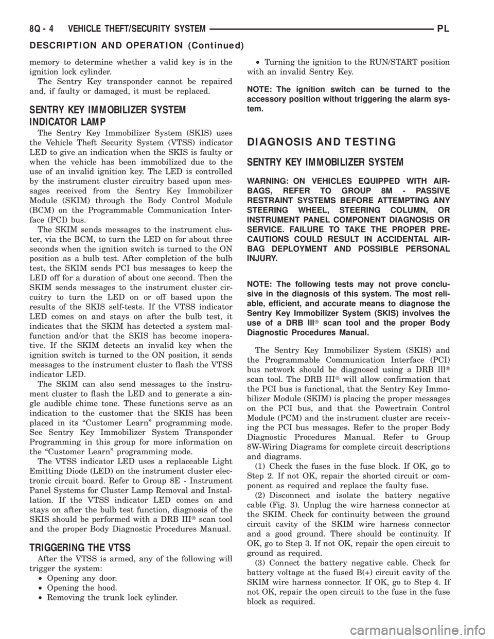
(2) Disconnect and isolate the battery negative
cable (Fig. 3). Unplug the wire harness connector at
the SKIM. Check for continuity between the ground
circuit cavity of the SKIM wire harness connector
and a good ground. There should be continuity. If
OK, go to Step 3. If not OK, repair the open circuit to
ground as required.
(3) Connect the battery negative cable. Check for
battery voltage at the fused B(+) circuit cavity of the
SKIM wire harness connector. If OK, go to Step 4. If
not OK, repair the open circuit to the fuse in the fuse
block as required.
8Q - 4 VEHICLE THEFT/SECURITY SYSTEMPL
DESCRIPTION AND OPERATION (Continued)
Page 378 of 1285
REMOVAL AND INSTALLATION
DOOR CYLINDER LOCK SWITCH
REMOVAL
(1) Refer to Group 23, Body for door trim and
water shield Removal and Installation.
(2) Remove illuminated entry switch wiring clip
and disconnect connector.
(3) Remove door cylinder lock switch from door
handle.
INSTALLATION
For installation reverse the above procedures.
HOOD AJAR SWITCH
REMOVAL
(1) Open hood.
(2) Disconnect and isolate the battery negative
remote cable (Fig. 3).
(3) Using a trim stick (special tool #C-4755) or
equivalent, gently pry switch up and out of mounting
bracket.
(4) Disconnect wire harness connector from hood
ajar switch.
(5) Remove switch from vehicle.
INSTALLATION
For installation reverse above procedures.
SENTRY KEY IMMOBILIZER MODULE (SKIM)
WARNING: ON VEHICLES EQUIPPED WITH AIR-
BAGS, REFER TO GROUP 8M - PASSIVE
RESTRAINT SYSTEMS BEFORE ATTEMPTING ANY
STEERING WHEEL, STEERING COLUMN, OR
INSTRUMENT PANEL COMPONENT DIAGNOSIS OR
SERVICE. FAILURE TO TAKE THE PROPER PRE-
CAUTIONS COULD RESULT IN ACCIDENTAL AIR-
BAG DEPLOYMENT AND POSSIBLE PERSONAL
INJURY.
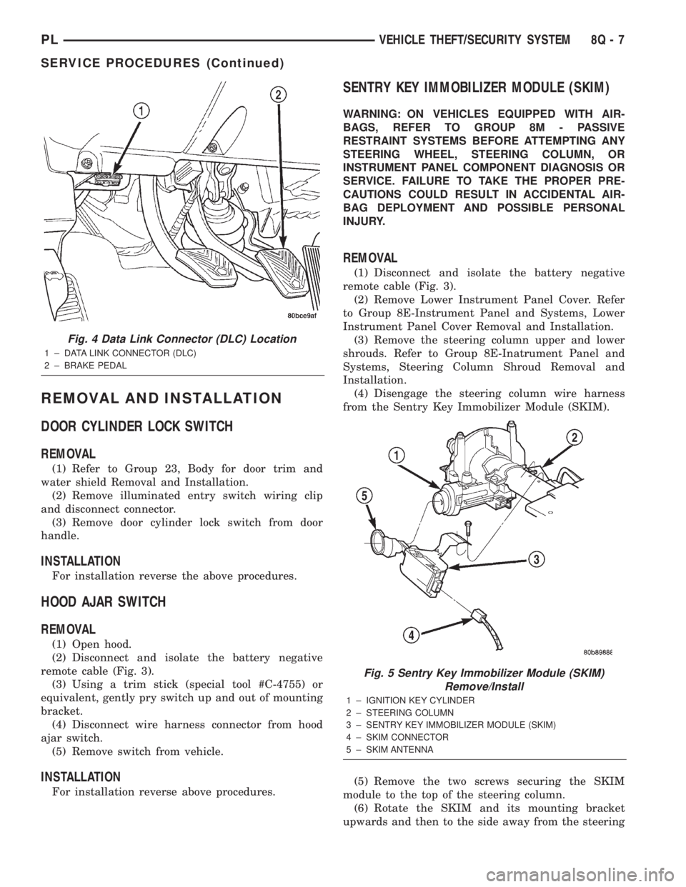
REMOVAL
(1) Disconnect and isolate the battery negative
remote cable (Fig. 3).
(2) Remove Lower Instrument Panel Cover. Refer
to Group 8E-Instrument Panel and Systems, Lower
Instrument Panel Cover Removal and Installation.
(3) Remove the steering column upper and lower
shrouds. Refer to Group 8E-Inatrument Panel and
Systems, Steering Column Shroud Removal and
Installation.
(4) Disengage the steering column wire harness
from the Sentry Key Immobilizer Module (SKIM).
(5) Remove the two screws securing the SKIM
module to the top of the steering column.
(6) Rotate the SKIM and its mounting bracket
upwards and then to the side away from the steering
Fig. 4 Data Link Connector (DLC) Location
1 ± DATA LINK CONNECTOR (DLC)
2 ± BRAKE PEDAL
Fig. 5 Sentry Key Immobilizer Module (SKIM)
Remove/Install
1 ± IGNITION KEY CYLINDER
2 ± STEERING COLUMN
3 ± SENTRY KEY IMMOBILIZER MODULE (SKIM)
4 ± SKIM CONNECTOR
5 ± SKIM ANTENNA
PLVEHICLE THEFT/SECURITY SYSTEM 8Q - 7
SERVICE PROCEDURES (Continued)
Page 390 of 1285
CHIME WARNING/REMINDER SYSTEM
TABLE OF CONTENTS
page page
DESCRIPTION AND OPERATION
INTRODUCTION..........................1
DIAGNOSIS AND TESTING
FASTEN SEAT BELTS......................1
HEADLAMPS LEFT ON.....................1
KEY LEFT IN IGNITION SWITCH.............1CHIME SYSTEM CONDITIONS...............1
REMOVAL AND INSTALLATION
CHIME..................................2
SEAT BELT BUCKLE.......................2
HEADLAMP SWITCH......................2
KEY-IN SWITCH..........................2
DESCRIPTION AND OPERATION
INTRODUCTION
WARNING: ON VEHICLES EQUIPPED WITH AN AIR-
BAG, REFER TO THE AIRBAG PORTION OF THIS
SECTION FOR STEERING WHEEL OR SWITCH
REMOVAL AND INSTALLATION PROCEDURES.
The seat belt reminder system uses both visual
and audible signals. A combined seat belt and key
reminder chime with a red light on the instrument
panel.
The system will always illuminate the seat belt
reminder lamp for four to eight seconds when the
ignition switch is turned to the ON position. The
CHIME will sound during the same time interval if
the driver's seat belt is not fastened. Passenger belts
are not connected to the system.
The chime will activate if the drivers door is
opened and:
²The key is in the ignition switch, with the igni-
tion switch in either the OFF or accessory (ACC)
position.
²The head lamps are ON.
The chime is integral to the instrument cluster.
DIAGNOSIS AND TESTING
FASTEN SEAT BELTS
To test the fasten seat belts function, turn the igni-
tion switch to the ON position with the driver's seat
belt unbuckled and fully retracted. The seat belt
warning lamp should light for four to eight seconds
and the tone should sound three to five times.
If the lamp does not light, check the connection at
the seat belt retractor and the LED in the instru-
ment cluster. Replace as necessary.
HEADLAMPS LEFT ON
These are the conditions that have to be met for
the headlamps on, chime function to work:
²Headlamps ON.
²Driver's door open.
²Key removed from the ignition switch.
Chime should sound until headlamps are turned
off or driver's door is closed.
If these conditions are met and there is still a
problem with the system, replace the instrument
cluster. Refer to Group 8E-Instrument Panel and
Systems, Instrument Cluster Removal and Installa-
tion.
KEY LEFT IN IGNITION SWITCH
To test the key left in ignition function, insert key
into the ignition and open the driver's door. Chime
should sound until key is removed from ignition or
driver's door is closed.
If these conditions are met and there is still a
problem with the system, replace the instrument
cluster. Refer to Group 8E-Instrument Panel and
Systems, Instrument Cluster Removal and Installa-
tion.
CHIME SYSTEM CONDITIONS
NO TONE WHEN IGNITION SWITCH IS TURNED ON
AND DRIVERS SEAT BELT IS UNBUCKLED
(1) Using an ohmmeter, with the seat belt fully
retracted, check for continuity to ground at Pin 25 of
the cluster harness connector. If OK, go to step 2. If
not OK, repair as necessary.
(2) Using voltmeter, check for battery feed at Pin
21 of the cluster harness connector. Check for igni-
tion feed at Pin 15 of the cluster harness connector.
If not OK, repair as necessary.
PLCHIME WARNING/REMINDER SYSTEM 8U - 1
Page 391 of 1285
NO FASTEN SEAT BELT LAMP WHEN IGNITION
SWITCH IS ON
(1) Check for battery feed at cluster harness con-
nector Pin 21.
(2) Check for ignition feed at cluster harness con-
nector Pin 15. Repair as necessary.
NO TONE WHEN HEADLAMPS ARE ON AND
DRIVERS DOOR IS OPEN
(1) Check left door jamb switch for good ground
when drivers door is open.
(2) Check for ground at Pin 10.
(3) Check for battery feed at cluster harness con-
nector Pin 21.
(4) Check for NO voltage at Pin 14. Ignition volt-
age must not be present for the chime to work.
(5) Check headlamp switch.
NO TONE WHEN KEY IS LEFT IN IGNITION AND
DRIVERS DOOR IS OPEN
(1) Check for continuity to ground at Pin 23 of the
cluster harness connector. If OK, go to Step 3. If not
OK, repair as necessary.
(2) Using voltmeter, check for battery feed at Pin
21 of the cluster harness connector. Check for NO
ignition feed at Pin 15 of the cluster harness connec-
tor. If OK, go to Step 3. If not OK, repair as neces-
sary.
(3) Open driver's door and ensure the ignition key
is in the OFF or ACC position. Check for continuity
to ground at Pin 10 of the cluster harness connector.
If ground OK, replace cluster printed circuit board. If
no ground, check key-in switch or door switch wiring
and repair as necessary.
CHIMES CONTINUE WHEN HEADLAMPS ARE
TURNED OFF AND/OR KEY IS REMOVED FROM
IGNITION
Check for ground at Pin 10. If grounded the chime
should activate. Make sure the door is closed, key isin ignition and parking lamps are OFF. If ground is
still present check door switch, key in switch, head-
lamp switch and repair as necessary.
REMOVAL AND INSTALLATION
CHIME
The functions previously performed by the chime
module are now part of the smart cluster. There is no
servicable part of the instrument cluster chime func-
tion. Replacement of the instrument cluster is neces-
sary. Refer to Group 8E-Instrument Panel and
Systems, Instrument Cluster Removal and Installa-
tion.
SEAT BELT BUCKLE
Refer to Group 23-Body, Front Seat Belt Buckle
Removal and Installation.
HEADLAMP SWITCH
Refer to Group 8J-Turn Signal and Hazard Warn-
ing Systems, Multi-Function Switch Removal and
Installation.
KEY-IN SWITCH
The Key-in switch is built into the ignition switch
assembly. Should the Key-in switch require service,
the ignition switch assembly must be replaced. Refer
to Group 8D-Ignition System, Ignition Switch
Removal and Installation.
8U - 2 CHIME WARNING/REMINDER SYSTEMPL
DIAGNOSIS AND TESTING (Continued)
Page 400 of 1285
TERMINOLOGY
This a list of terms with there definitions used in
the wiring diagrams.
Built-Up-Export....... Vehicles Built For Sale In
Markets Other Than North America
Except-Built-Up-Export . Vehicles Built For Sale In
North America
LHD ................Left Hand Drive Vehicles
RHD ...............Right Hand Drive Vehicles
ATX . . Automatic Transmission-Front Wheel Drive
MTX ....Manual Transmission-Front Wheel Drive
AT ....Automatic Transmission-Rear Wheel Drive
MT......Manual Transmission-Rear Wheel Drive
SOHC...........Single Over Head Cam Engine
DOHC............Dual Over Head Cam Engine
CONNECTOR INFORMATION
CAUTION: Not all connectors are serviced. Some
connectors are serviced only with a harness. A typ-
ical example might be the Supplemental Restraint
System connectors. Always check parts availability
before attempting a repair.
IDENTIFICATION
In-line connectors are identified by a number, as
follows:
²In-line connectors located on theengine com-
partment harnessareC100series numbers.
²Connectors located on theinstrument panel
harnessareC200series numbers.
²Connectors located on thebody harnessare
C300series numbers.
²Jumper harness connectorsareC400series
numbers.
²Grounds and ground connectorsare identi-
fied with aªGºand follow the same series number-
ing as the in-line connector.
Component connectors are identified by the compo-
nent name instead of a number. Multiple connectors
on a component use a C1, C2, etc. identifier.
LOCATIONS
Section 8W-90 contains connector/ground location
illustrations. The illustrations contain the connector
name (or number)/ground number and component
identification. Connector/ground location charts in
Section 8W-90 reference the illustration number for
components and connectors.
Section 8W-80 shows each connector and the cir-
cuits involved with that connector. The connectors
are identified using the name/number on the Dia-
gram pages.
SPLICE LOCATIONS
Splice Location charts in Section 8W-70 show the
entire splice, and provide references to other sections
the splice serves.
Section 8W-95 contains illustrations that show the
general location of the splices in each harness. The
illustrations show the splice by number, and provide
a written location.
NOTES, CAUTIONS, and WARNINGS
Throughout this group additional important infor-
mation is presented in three ways; Notes, Cautions,
and Warnings.
NOTESare used to help describe how switches or
components operate to complete a particular circuit.
They are also used to indicate different conditions
that may appear on the vehicle. For example, an
up-to and after condition.
CAUTIONSare used to indicate information that
could prevent making an error that may damage the
vehicle.
WARNINGSprovide information to prevent per-
sonal injury and vehicle damage. Below is a list of
general warnings that should be followed any time a
vehicle is being serviced.
WARNING: ALWAYS WEAR SAFETY GLASSES FOR
EYE PROTECTION.
WARNING: USE SAFETY STANDS ANYTIME A PRO-
CEDURE REQUIRES BEING UNDER A VEHICLE.
WARNING: BE SURE THAT THE IGNITION SWITCH
ALWAYS IS IN THE OFF POSITION, UNLESS THE
PROCEDURE REQUIRES IT TO BE ON.
WARNING: SET THE PARKING BRAKE WHEN
WORKING ON ANY VEHICLE. AN AUTOMATIC
TRANSMISSION SHOULD BE IN PARK. A MANUAL
TRANSMISSION SHOULD BE IN NEUTRAL.
WARNING: OPERATE THE ENGINE ONLY IN A
WELL-VENTILATED AREA.
WARNING: KEEP AWAY FROM MOVING PARTS
WHEN THE ENGINE IS RUNNING, ESPECIALLY THE
FAN AND BELTS.
WARNING: TO PREVENT SERIOUS BURNS, AVOID
CONTACT WITH HOT PARTS SUCH AS THE RADIA-
TOR, EXHAUST MANIFOLD(S), TAIL PIPE, CATA-
LYTIC CONVERTER, AND MUFFLER.
PL8W - 01 GENERAL INFORMATION 8W - 01 - 7
DESCRIPTION AND OPERATION (Continued)