2000 DODGE NEON instrument panel
[x] Cancel search: instrument panelPage 267 of 1285
(17) Install the A/C outlet registers in the center
instrument bezel.
(18) Install the right and left side lower kick pan-
els. Reposition the weather-strip in its original posi-
tion.
(19) Install the steering column. Torque the retain-
ing nuts to 17 N´m (150 in. lbs.).
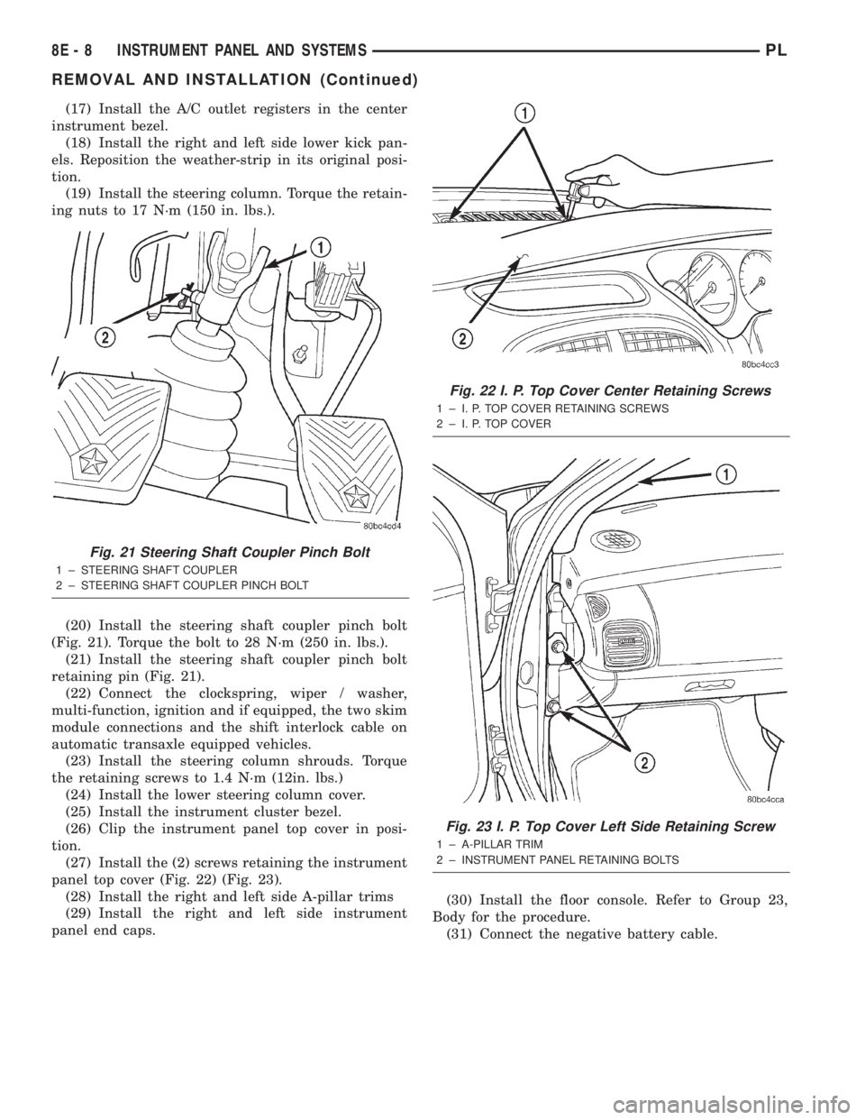
(20) Install the steering shaft coupler pinch bolt
(Fig. 21). Torque the bolt to 28 N´m (250 in. lbs.).
(21) Install the steering shaft coupler pinch bolt
retaining pin (Fig. 21).
(22) Connect the clockspring, wiper / washer,
multi-function, ignition and if equipped, the two skim
module connections and the shift interlock cable on
automatic transaxle equipped vehicles.
(23) Install the steering column shrouds. Torque
the retaining screws to 1.4 N´m (12in. lbs.)
(24) Install the lower steering column cover.
(25) Install the instrument cluster bezel.
(26) Clip the instrument panel top cover in posi-
tion.
(27) Install the (2) screws retaining the instrument
panel top cover (Fig. 22) (Fig. 23).
(28) Install the right and left side A-pillar trims
(29) Install the right and left side instrument
panel end caps.(30) Install the floor console. Refer to Group 23,
Body for the procedure.
(31) Connect the negative battery cable.
Fig. 21 Steering Shaft Coupler Pinch Bolt
1 ± STEERING SHAFT COUPLER
2 ± STEERING SHAFT COUPLER PINCH BOLT
Fig. 22 I. P. Top Cover Center Retaining Screws
1 ± I. P. TOP COVER RETAINING SCREWS
2 ± I. P. TOP COVER
Fig. 23 I. P. Top Cover Left Side Retaining Screw
1 ± A-PILLAR TRIM
2 ± INSTRUMENT PANEL RETAINING BOLTS
8E - 8 INSTRUMENT PANEL AND SYSTEMSPL
REMOVAL AND INSTALLATION (Continued)
Page 268 of 1285
SPECIFICATIONS
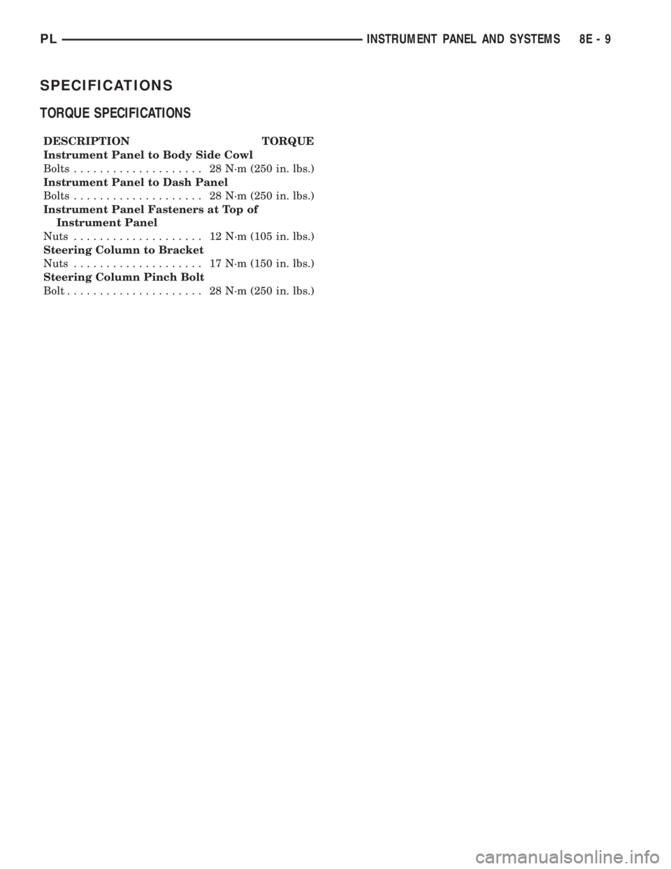
TORQUE SPECIFICATIONS
DESCRIPTION TORQUE
Instrument Panel to Body Side Cowl
Bolts.................... 28N´m(250 in. lbs.)
Instrument Panel to Dash Panel
Bolts.................... 28N´m(250 in. lbs.)
Instrument Panel Fasteners at Top of
Instrument Panel
Nuts.................... 12N´m(105 in. lbs.)
Steering Column to Bracket
Nuts.................... 17N´m(150 in. lbs.)
Steering Column Pinch Bolt
Bolt..................... 28N´m(250 in. lbs.)
PLINSTRUMENT PANEL AND SYSTEMS 8E - 9
Page 270 of 1285
AUDIO SYSTEM
TABLE OF CONTENTS
page page
GENERAL INFORMATION
INTRODUCTION..........................1
DESCRIPTION AND OPERATION
INTERFERENCE ELIMINATION...............1
DIAGNOSIS AND TESTING
AUDIO DIAGNOSTIC TEST PROCEDURES......1
TESTING................................1
BENCH TEST FOR ANTENNA MALFUNCTION...7REMOVAL AND INSTALLATION
CD CHANGER............................7
FRONT DOOR SPEAKER....................8
INSTRUMENT PANEL SPEAKER(S)...........8
MAST and ANTENNA ASSEMBLY.............8
RADIO..................................9
REAR SHELF SPEAKER(S).................10
GENERAL INFORMATION
INTRODUCTION
Operating instructions for the factory installed
audio systems can be found in the Owner's Manual
provided with the vehicle.
The vehicles are equipped with an Interior (Igni-
tion Off Draw) fuse in the Power Distribution Center
located in the engine compartment. After the Interior
(IOD) fuse or battery has been disconnected the clock
will require resetting. The radio station presets have
a nonvolatile memory and will retain the preset sta-
tions after a battery disconnect.
The available radio options are:
²AM/FM Stereo Cassette w/Clock
²AM/FM/CD
²AM/FM Cassette w/CD Changer Controls and
Display
²CD/4 Disc Changer - In-Dash (used w/Radio CD
Changer Controls)
DESCRIPTION AND OPERATION
INTERFERENCE ELIMINATION
The radio utilizes a ground wire plugged on to a
blade terminal and is bolted to the radio chassis.
Both connector and terminal should be securely
attached. The engine has two separate ground straps
to suppress ignition noise which may interfere with
radio reception.
²Left engine mount clip on strap
²Engine to shock tower reinforcement
Inductive type spark plug cables in the high ten-
sion circuit of the ignition system complete the inter-
ference suppression. Faulty or deteriorated spark
plug wires should be replaced.
DIAGNOSIS AND TESTING
AUDIO DIAGNOSTIC TEST PROCEDURES
CAUTION: The CD player will only operate between
approximate temperatures of -23ÉC and +65ÉC (-10ÉF
and +145ÉF).
Whenever a radio malfunction occurs;
(1) First check FUSES:
(a) Power Distribution Center (PDC), Interior
lamp fuse, M1 - Radio Memory Feed
(b) Fuse Block:
(I) Fuse 12, Illumination in the fuse block
(II) Fuse 16, Ignition feed in the fuse block
NOTE: The vehicles are shipped with the INTERIOR
LAMP fuse disconnected.
(2) Verify, the radio wire harness are properly con-
nected before starting normal diagnosis and repair
procedures. Refer to Audio Diagnostic Charts and/or
Group 8W, Wiring Diagrams, Radio Section.
TESTING
The antenna has a short cable which connects into
the instrument panel harness. The connection is
made on the right side of the instrument panel.
Antenna performance may be tested by substitut-
ing a known good antenna. It is also possible to
check short or open circuits with an ohmmeter or
continuity light once the antenna cable is discon-
nected from the radio as follows:
(1) Continuity should be present between the
antenna mast and radio end pin of antenna cable
plug (Fig. 1).
(2) No continuity should be observed or a very
high resistance of several megohms between the
ground shell of the connector and radio end pin.
PLAUDIO SYSTEM 8F - 1
Page 277 of 1285
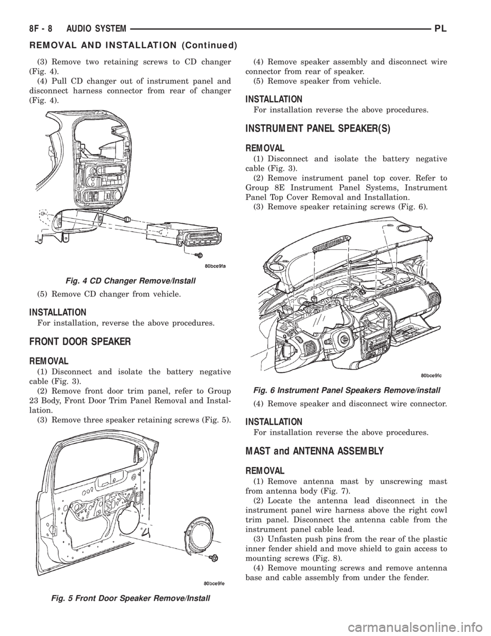
(3) Remove two retaining screws to CD changer
(Fig. 4).
(4) Pull CD changer out of instrument panel and
disconnect harness connector from rear of changer
(Fig. 4).
(5) Remove CD changer from vehicle.
INSTALLATION
For installation, reverse the above procedures.
FRONT DOOR SPEAKER
REMOVAL
(1) Disconnect and isolate the battery negative
cable (Fig. 3).
(2) Remove front door trim panel, refer to Group
23 Body, Front Door Trim Panel Removal and Instal-
lation.
(3) Remove three speaker retaining screws (Fig. 5).(4) Remove speaker assembly and disconnect wire
connector from rear of speaker.
(5) Remove speaker from vehicle.
INSTALLATION
For installation reverse the above procedures.
INSTRUMENT PANEL SPEAKER(S)
REMOVAL
(1) Disconnect and isolate the battery negative
cable (Fig. 3).
(2) Remove instrument panel top cover. Refer to
Group 8E Instrument Panel Systems, Instrument
Panel Top Cover Removal and Installation.
(3) Remove speaker retaining screws (Fig. 6).
(4) Remove speaker and disconnect wire connector.
INSTALLATION
For installation reverse the above procedures.
MAST and ANTENNA ASSEMBLY
REMOVAL
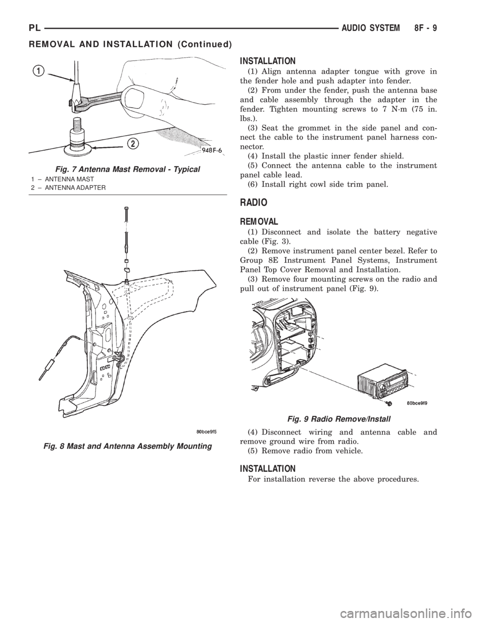
(1) Remove antenna mast by unscrewing mast
from antenna body (Fig. 7).
(2) Locate the antenna lead disconnect in the
instrument panel wire harness above the right cowl
trim panel. Disconnect the antenna cable from the
instrument panel cable lead.
(3) Unfasten push pins from the rear of the plastic
inner fender shield and move shield to gain access to
mounting screws (Fig. 8).
(4) Remove mounting screws and remove antenna
base and cable assembly from under the fender.
Fig. 4 CD Changer Remove/Install
Fig. 5 Front Door Speaker Remove/Install
Fig. 6 Instrument Panel Speakers Remove/install
8F - 8 AUDIO SYSTEMPL
REMOVAL AND INSTALLATION (Continued)
Page 278 of 1285
INSTALLATION
(1) Align antenna adapter tongue with grove in
the fender hole and push adapter into fender.
(2) From under the fender, push the antenna base
and cable assembly through the adapter in the
fender. Tighten mounting screws to 7 N´m (75 in.
lbs.).
(3) Seat the grommet in the side panel and con-
nect the cable to the instrument panel harness con-
nector.
(4) Install the plastic inner fender shield.
(5) Connect the antenna cable to the instrument
panel cable lead.
(6) Install right cowl side trim panel.
RADIO
REMOVAL
(1) Disconnect and isolate the battery negative
cable (Fig. 3).
(2) Remove instrument panel center bezel. Refer to
Group 8E Instrument Panel Systems, Instrument
Panel Top Cover Removal and Installation.
(3) Remove four mounting screws on the radio and
pull out of instrument panel (Fig. 9).
(4) Disconnect wiring and antenna cable and
remove ground wire from radio.
(5) Remove radio from vehicle.
INSTALLATION
For installation reverse the above procedures.
Fig. 7 Antenna Mast Removal - Typical
1 ± ANTENNA MAST
2 ± ANTENNA ADAPTER
Fig. 8 Mast and Antenna Assembly Mounting
Fig. 9 Radio Remove/Install
PLAUDIO SYSTEM 8F - 9
REMOVAL AND INSTALLATION (Continued)
Page 288 of 1285
On most vehicles another resistor has been added
to the at rest circuit causing the PCM to never see 5
volts. This was done for diagnostic purposes. If the
switch circuit should open (bad connection) then the
PCM will see the 5 volts and know the circuit is bad.
The PCM will then set an open circuit fault.
STOP LAMP SWITCH
DESCRIPTION
The switch is mounted on the brake pedal mount-
ing bracket under the instrument panel.
OPERATION
Vehicles equipped with the speed control option use
a dual function stop lamp switch. The PCM monitors
the state of the dual function stop lamp switch. Refer
to the Brake section for more information on stop
lamp switch service and adjustment procedures.
The brake switch is equipped with three sets of
contacts, one normally open and the other two nor-
mally closed (brakes disengaged). The PCM sends a
12 volt signal to one of the normally closed contacts
in the brake switch, which is connected to a ground.
With the contacts closed, the 12 volt signal is pulled
to ground causing the signal to go low. The low volt-
age signal, monitored by the PCM, indicates that the
brakes are not applied. When the brakes are applied,
the contacts open, causing the PCM's output voltage
to go high, disengaging the speed control also
grounding the dump solenoid.
The second set of normally closed contacts is sup-
plied battery voltage any time speed control is
selected. From the brake switch, current is routed to
the speed control servo solenoids. The speed control
solenoids (vacuum, vent and dump) are provided this
current any time the speed control is ON and the
brakes are disengaged. When the driver applies the
brakes, the contacts open and current is interrupted
to the solenoids. The normally open contacts are fed
battery voltage. When the brakes are applied, battery
voltage is supplied to the stop lamps.
SERVO CABLE
DESCRIPTION
The speed control servo cable is connected between
the speed control vacuum servo diaphragm and the
throttle body control linkage.
OPERATION
This cable causes the throttle control linkage to
open or close the throttle valve in response to move-
ment of the vacuum servo diaphragm.
VACUUM RESERVOIR
OPERATION
The reservoir stores engine vacuum in the reser-
voir. When engine vacuum drops, as in climbing a
grade while driving, the reservoir supplies the vac-
uum needed to maintain proper speed control opera-
tion. The vacuum reservoir cannot be repaired and
must be replaced if faulty.
VEHICLE SPEED SENSOR
The Vehicle Speed Sensor (VSS) is a pulse genera-
tor mounted to an adapter near the transmission out-
put shaft. The sensor is driven through the adapter
by a speedometer pinion gear. The VSS pulse signal
to the speedometer/odometer is monitored by the
PCM speed control circuitry to determine vehicle
speed and to maintain speed control set speed.
REMOVAL AND INSTALLATION
SPEED CONTROL SERVO
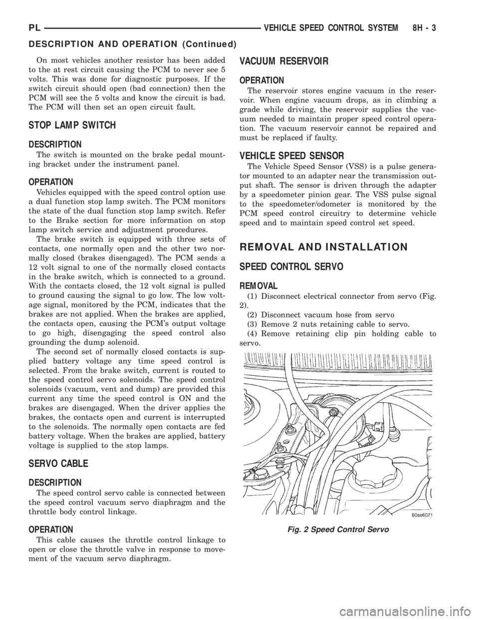
REMOVAL
(1) Disconnect electrical connector from servo (Fig.
2).
(2) Disconnect vacuum hose from servo
(3) Remove 2 nuts retaining cable to servo.
(4) Remove retaining clip pin holding cable to
servo.
Fig. 2 Speed Control Servo
PLVEHICLE SPEED CONTROL SYSTEM 8H - 3
DESCRIPTION AND OPERATION (Continued)
Page 292 of 1285
TURN SIGNAL and HAZARD WARNING SYSTEMS
TABLE OF CONTENTS
page page
GENERAL INFORMATION
INTRODUCTION..........................1
DESCRIPTION AND OPERATION
HAZARD WARNING SYSTEM................2
HEADLAMP SWITCH......................2
COMBINATION FLASHER...................2DIAGNOSIS AND TESTING
MULTI-FUNCTION SWITCH.................3
REMOVAL AND INSTALLATION
COMBINATION FLASHER...................5
MULTI-FUNCTION SWITCH.................5
GENERAL INFORMATION
INTRODUCTION
WARNING: ON VEHICLES EQUIPPED WITH AIR-
BAG, SEE GROUP 8M, PASSIVE RESTRAINT SYS-
TEMS FOR AIRBAG REMOVAL.
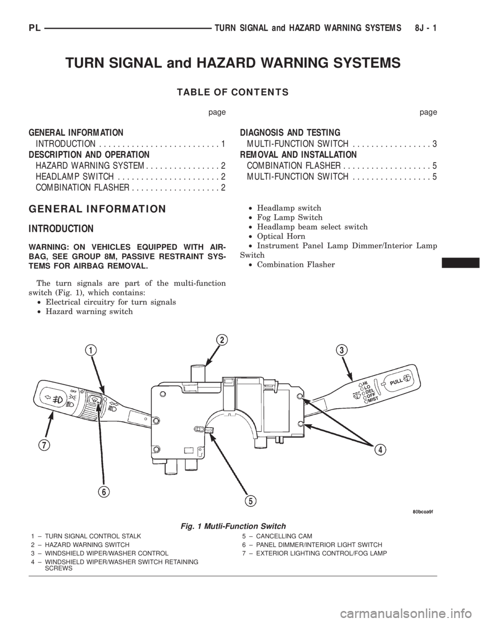
The turn signals are part of the multi-function
switch (Fig. 1), which contains:
²Electrical circuitry for turn signals
²Hazard warning switch²Headlamp switch
²Fog Lamp Switch
²Headlamp beam select switch
²Optical Horn
²Instrument Panel Lamp Dimmer/Interior Lamp
Switch
²Combination Flasher
Fig. 1 Mutli-Function Switch
1 ± TURN SIGNAL CONTROL STALK
2 ± HAZARD WARNING SWITCH
3 ± WINDSHIELD WIPER/WASHER CONTROL
4 ± WINDSHIELD WIPER/WASHER SWITCH RETAINING
SCREWS5 ± CANCELLING CAM
6 ± PANEL DIMMER/INTERIOR LIGHT SWITCH
7 ± EXTERIOR LIGHTING CONTROL/FOG LAMP
PLTURN SIGNAL and HAZARD WARNING SYSTEMS 8J - 1
Page 293 of 1285
The integrated switch assembly is mounted to the
left hand side of the steering column. When the
driver wishes to signal his intentions to change direc-
tion of travel, he moves the lever upward to cause
the right signals to flash and downward to cause the
left signals to flash. After completion of a turn the
system is deactivated automatically. As the steering
wheel returns to the straight ahead position, a can-
celing cam molded to the clockspring mechanism
comes in contact with the cancel actuator on the turn
signal multi-function switch assembly. The cam lobe,
pushing on the cancel actuator, returns the switch to
the off position.
If only momentary signaling such as indication of a
lane change is desired, the switch is actuated to a
left or right intermediate detent position. In this
position the signal lamps flash as described above,
but the switch returns to the OFF position as soon as
the lever is released.
When the system is activated, one of two indicator
lamps mounted in the instrument cluster flashes in
unison with the turn signal lamps, indicating to the
driver that the system is operating.
DESCRIPTION AND OPERATION
HAZARD WARNING SYSTEM
The hazard warning system is actuated by a push
button located in the muti-function switch (Fig. 1) on
the top of the steering column between the steering
wheel and the instrument panel. The hazard switch
is identified with a double triangle on front of the
button.
HEADLAMP SWITCH
The headlamp switch is part of the Multi-Function
Switch (Fig. 1). Refer to Multi-Function Switch Diag-
nosis and Testing, Turn Signal and Hazard Warning
Flasher Diagnosis table in this section.
COMBINATION FLASHER
The turn signal flasher and the hazard warning
flasher are combined into one unit called a combina-
tion flasher (combo-flasher). The combo- flasher con-
trols the flashing of the hazard warning system and
the turn signal system. An inoperative bulb or incom-
plete turn signal circuit will cause the flasher rate to
double.
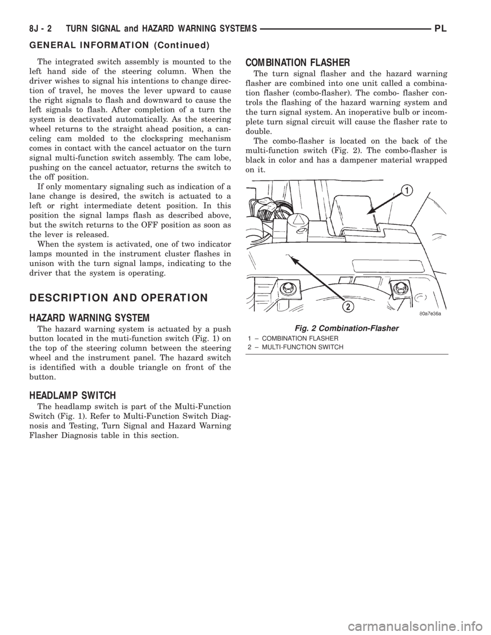
The combo-flasher is located on the back of the
multi-function switch (Fig. 2). The combo-flasher is
black in color and has a dampener material wrapped
on it.
Fig. 2 Combination-Flasher
1 ± COMBINATION FLASHER
2 ± MULTI-FUNCTION SWITCH
8J - 2 TURN SIGNAL and HAZARD WARNING SYSTEMSPL
GENERAL INFORMATION (Continued)