Page 295 of 1285
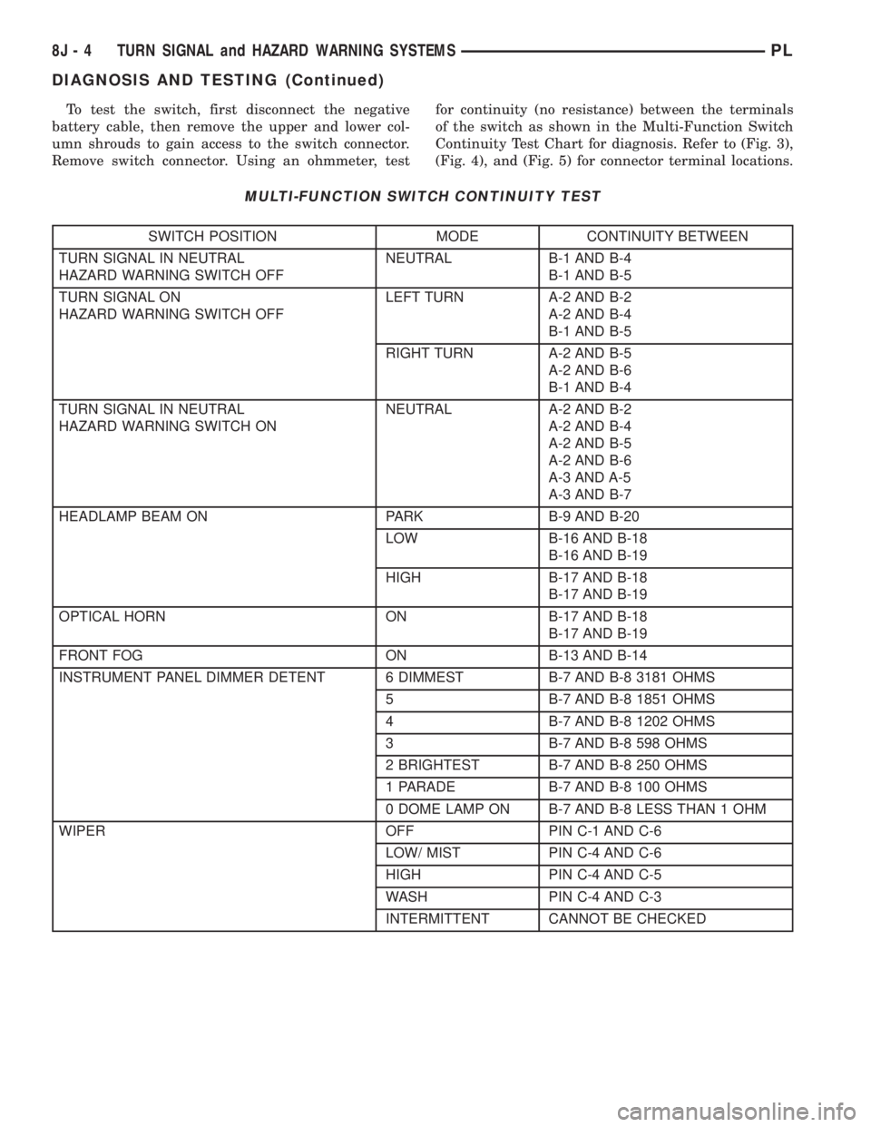
To test the switch, first disconnect the negative
battery cable, then remove the upper and lower col-
umn shrouds to gain access to the switch connector.
Remove switch connector. Using an ohmmeter, testfor continuity (no resistance) between the terminals
of the switch as shown in the Multi-Function Switch
Continuity Test Chart for diagnosis. Refer to (Fig. 3),
(Fig. 4), and (Fig. 5) for connector terminal locations.
MULTI-FUNCTION SWITCH CONTINUITY TEST
SWITCH POSITION MODE CONTINUITY BETWEEN
TURN SIGNAL IN NEUTRAL
HAZARD WARNING SWITCH OFFNEUTRAL B-1 AND B-4
B-1 AND B-5
TURN SIGNAL ON
HAZARD WARNING SWITCH OFFLEFT TURN A-2 AND B-2
A-2 AND B-4
B-1 AND B-5
RIGHT TURN A-2 AND B-5
A-2 AND B-6
B-1 AND B-4
TURN SIGNAL IN NEUTRAL
HAZARD WARNING SWITCH ONNEUTRAL A-2 AND B-2
A-2 AND B-4
A-2 AND B-5
A-2 AND B-6
A-3 AND A-5
A-3 AND B-7
HEADLAMP BEAM ON PARK B-9 AND B-20
LOW B-16 AND B-18
B-16 AND B-19
HIGH B-17 AND B-18
B-17 AND B-19
OPTICAL HORN ON B-17 AND B-18
B-17 AND B-19
FRONT FOG ON B-13 AND B-14
INSTRUMENT PANEL DIMMER DETENT 6 DIMMEST B-7 AND B-8 3181 OHMS
5 B-7 AND B-8 1851 OHMS
4 B-7 AND B-8 1202 OHMS
3 B-7 AND B-8 598 OHMS
2 BRIGHTEST B-7 AND B-8 250 OHMS
1 PARADE B-7 AND B-8 100 OHMS
0 DOME LAMP ON B-7 AND B-8 LESS THAN 1 OHM
WIPER OFF PIN C-1 AND C-6
LOW/ MIST PIN C-4 AND C-6
HIGH PIN C-4 AND C-5
WASH PIN C-4 AND C-3
INTERMITTENT CANNOT BE CHECKED
8J - 4 TURN SIGNAL and HAZARD WARNING SYSTEMSPL
DIAGNOSIS AND TESTING (Continued)
Page 296 of 1285
REMOVAL AND INSTALLATION
COMBINATION FLASHER
The flasher is mounted to the back side of the
multi-function switch (Fig. 2). To gain access the
upper steering column shroud must be removed.
Refer to Group 8E Instrument Panel Systems, Steer-
ing Column Shroud Removal and Installation. The
flasher can be removed by pulling it toward the
instrument cluster (forward). The flasher is serviced
separately from the multi-function switch.
MULTI-FUNCTION SWITCH
REMOVAL
(1) Disconnect and isolate the battery negative
cable (Fig. 6).
(2) Remove both upper and lower steering column
shrouds. Refer to Group 8E Instrument Panel Sys-
tems, Steering Column Shroud Removal and Instal-
lation.
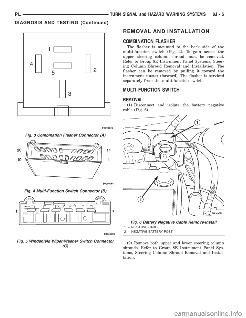
Fig. 3 Combination Flasher Connector (A)
Fig. 4 Multi-Function Switch Connector (B)
Fig. 5 Windshield Wiper/Washer Switch Connector
(C)
Fig. 6 Battery Negative Cable Remove/Install
1 ± NEGATIVE CABLE
2 ± NEGATIVE BATTERY POST
PLTURN SIGNAL and HAZARD WARNING SYSTEMS 8J - 5
DIAGNOSIS AND TESTING (Continued)
Page 318 of 1285
INSTALLATION
(1) Push bulb in socket and snap into place.
(2) Install floor console.
GLOVE BOX LAMP BULB
REMOVAL
(1) Open glove box door.
(2) Pull downward on lamp/switch assembly to dis-
engage tabs from instrument panel.
(3) Pull bulb from socket.
INSTALLATION
(1) Push bulb into socket.
(2) Place lamp/switch assembly into position.
(3) Push lamp/switch assembly to lock tabs.
(4) Check lamp operation, and close glove door.
FLOOR CONSOLE LAMP BULB
REMOVAL
(1) Using a flat bladed tool, slide it between the
lamp and instrument panel to disengage tabs.(2) Remove bulb from lamp socket.
INSTALLATION
(1) Install bulb into socket.
(2) Place lamp into position.
(3) Push lamp to lock tabs.
(4) Check lamp operation.
VISOR VANITY LAMP BULB
REMOVAL
(1) Lower visor.
(2) Insert a small flat bladed tool between the
lamp lens and lamp.
(3) Carefully pry lens outward.
(4) Remove bulb from socket.
INSTALLATION
(1) Position bulb in socket and snap into place.
(2) Position lens on lamp and snap into place.
PLLAMPS 8L - 11
REMOVAL AND INSTALLATION (Continued)
Page 322 of 1285
INSTALLATION
(1) Position lamp on hood and install screw.
(2) Connect lamp wire connector.
(3) Install lamp bulb.
(4) Install lens lamp.
(5) Close hood.
REAR CARGO LAMP
REMOVAL
(1) Insert a trim stick or small flat blade between
the lamp lens and rear shelf reinforcement panel.
(2) Pry the lamp lens downward.
(3) Disconnect wire connector.
(4) Remove lamp from vehicle.
INSTALLATION
(1) Place lamp into position.
(2) Connect wire connector.
(3) Install lamp lens.
DOME LAMP
REMOVAL
(1) Insert a trim stick between the dome lamp
bezel and dome lamp lens. Carefully pry down on one
side of the lamp lens.(2) Carefully pull down on lamp lens to remove
lamp from headliner.
(3) Disconnect wire connector.
(4) Remove lamp from vehicle.
INSTALLATION
(1) Place lamp into position.
(2) Connect wire connector.
(3) Install dome lamp and lens.
GLOVE BOX LAMP BULB
REMOVAL
(1) Open glove box door.
(2) Pull downward on lamp/switch assembly to dis-
engage tabs from instrument panel.
(3) Pull bulb from socket.
(4) Disconnect wire connector from lamp and
remove glove box lamp/switch.
INSTALLATION
(1) Push bulb into socket.
(2) Place lamp/switch assembly into position.
(3) Connect wire connector to the lamp/switch.
(4) Push lamp/switch assembly to lock tabs.
(5) Check lamp operation, and close glove door.
FLOOR CONSOLE LAMP BULB
REMOVAL
(1) Using a flat bladed tool, slide it between the
lamp and instrument panel to disengage tabs.
(2) Remove bulb from lamp socket.
INSTALLATION
(1) Install bulb into socket.
(2) Place lamp into position.
(3) Push lamp to lock tabs.
(4) Check lamp operation.
VISOR VANITY LAMP
The visor vanity lamp is incorporated in the visor
assembly. Replace the visor if the lamp has failed.
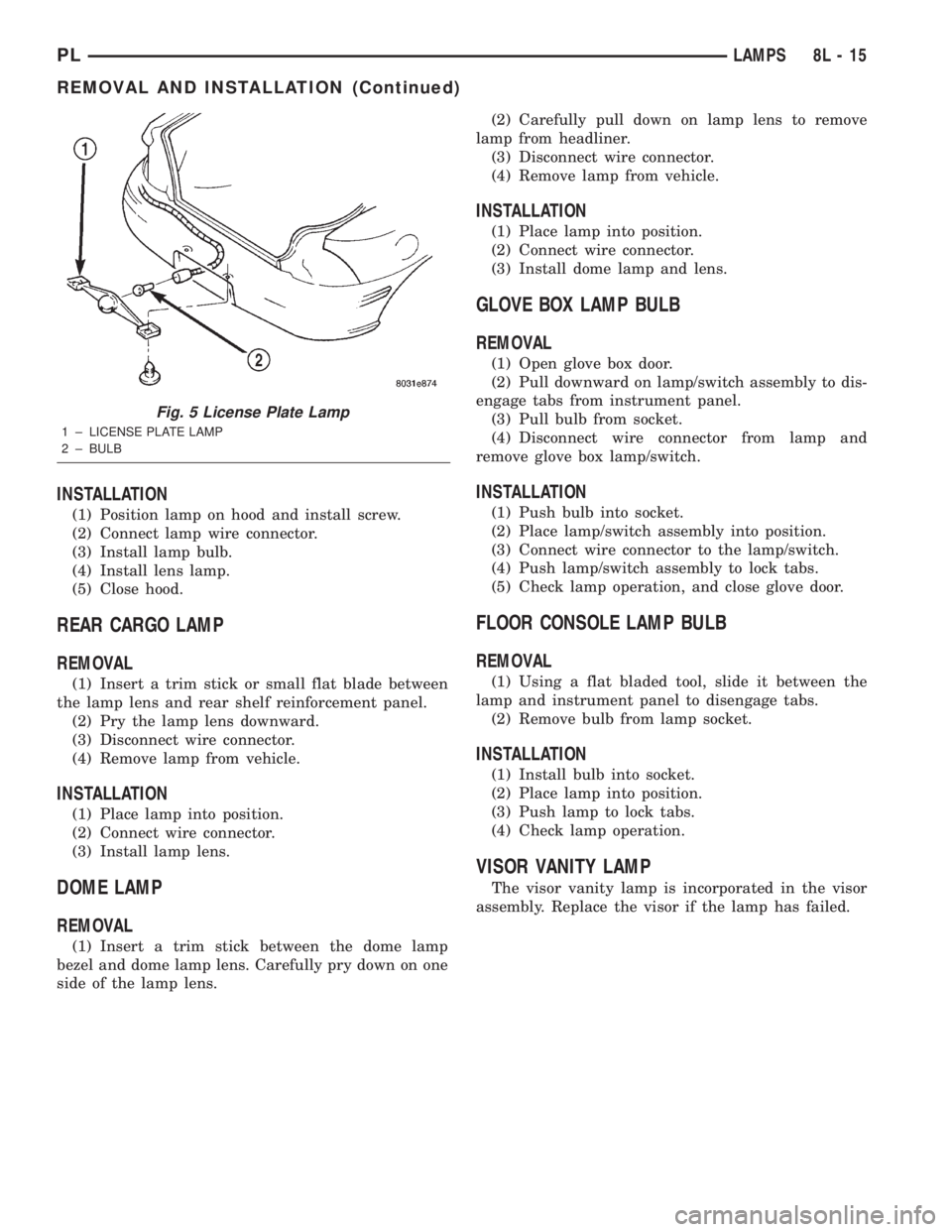
Fig. 5 License Plate Lamp
1 ± LICENSE PLATE LAMP
2 ± BULB
PLLAMPS 8L - 15
REMOVAL AND INSTALLATION (Continued)
Page 323 of 1285
LAMP SYSTEMS
DESCRIPTION AND OPERATION
DAYTIME RUNNING LAMP MODULE
PL vehicles built for use in Canada are equipped
with a Daytime Running Lamp (DRL) system. The
DRL function is provided by the cluster. The DRL
Module is an integral part of the instrument panel
cluster.
8L - 16 LAMPSPL
Page 324 of 1285
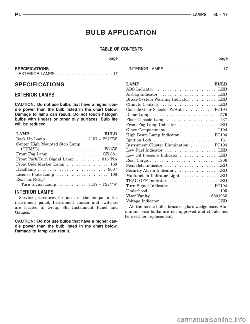
BULB APPLICATION
TABLE OF CONTENTS
page page
SPECIFICATIONS
EXTERIOR LAMPS........................17INTERIOR LAMPS........................17
SPECIFICATIONS
EXTERIOR LAMPS
CAUTION: Do not use bulbs that have a higher can-
dle power than the bulb listed in the chart below.
Damage to lamp can result. Do not touch halogen
bulbs with fingers or other oily surfaces. Bulb life
will be reduced.
LAMP BULB
Back Up Lamp................3157 ± P27/7W
Center High Mounted Stop Lamp
(CHMSL).........................W16W
Front Fog Lamp..................... GE881
Front Park/Turn Signal Lamp..........3157NA
Front Side Marker Lamp................. 168
Headlamp............................9007
License Plate Lamp..................... 168
Rear Tail/Stop/
Turn Signal Lamp............3157 ± P27/7W
INTERIOR LAMPS
Service procedures for most of the lamps in the
instrument panel, Instrument cluster and switches
are located in Group 8E, Instrument Panel and
Gauges.
CAUTION: Do not use bulbs that have a higher can-
dle power than the bulb listed in the chart below.
Damage to lamp can result.LAMP BULB
ABS Indicator......................... LED
Airbag Indicator....................... LED
Brake System Warning Indicator.......... LED
Climate Controls....................... LED
Console Gear Selector W/Auto...........PC194
Dome Lamp..........................T579
Floor Console Lamp..................... T37
Front Fog Lamp Indicator................ LED
Glove Compartment....................T194
High Beam Lamp Indicator.............PC194
Ignition Lock........................... 161
Instrument Cluster Illumination.........PC194
Low Fuel Indicator..................... LED
Low Oil Pressure Indicator............... LED
Rear Cargo...........................T906
Seat Belt Indicator..................... LED
Security Alarm Indicator................. LED
Malfunction Indicator Light.............. LED
TRAC OFF Indicator.................... LED
Turn Signal Indicator..................PC194
Underhood............................ 105
Visor Vanity........................6501966
Voltage Indicator....................... LED
All the inside bulbs brass or glass wedge base. Alu-
minum base bulbs are not approved and should not
be used for replacement.
PLLAMPS 8L - 17
Page 326 of 1285
LAMPS
TABLE OF CONTENTS
page page
LAMP DIAGNOSIS......................... 1
HEADLAMP ALIGNMENT.................... 2
LAMP BULB SERVICE...................... 4LAMP SERVICE........................... 12
BULB APPLICATION....................... 19
LAMP DIAGNOSIS
TABLE OF CONTENTS
page
GENERAL INFORMATION
HEADLAMP LEVELING MOTOR...............1
GENERAL INFORMATION
HEADLAMP LEVELING MOTOR
This vehicle is equipped with a remote headlamp
leveling system. This system allows the driver to
adjust the vertical headlamp aim from the interior of
the vehicle to compensate for passenger or cargo
load. A headlamp leveling switch is located in the
instrument panel (Fig. 1) and controls the headlamp
leveling motor which is mounted to the rear of the
headlamp assembly.
Fig. 1 Headlamp Leveling Switch Position &
Orientation
1 ± HEAD LAMP LEVELING SWITCH
2 ± CENTER INSTRUMENT BEZEL
PLLAMPS 8L - 1
Page 337 of 1285
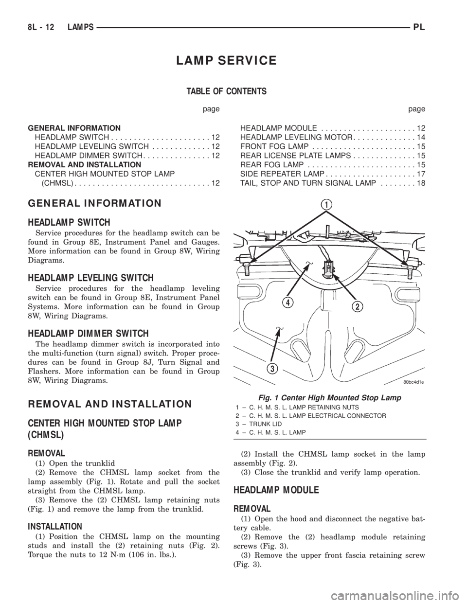
LAMP SERVICE
TABLE OF CONTENTS
page page
GENERAL INFORMATION
HEADLAMP SWITCH......................12
HEADLAMP LEVELING SWITCH.............12
HEADLAMP DIMMER SWITCH...............12
REMOVAL AND INSTALLATION
CENTER HIGH MOUNTED STOP LAMP
(CHMSL)..............................12HEADLAMP MODULE.....................12
HEADLAMP LEVELING MOTOR..............14
FRONT FOG LAMP.......................15
REAR LICENSE PLATE LAMPS..............15
REAR FOG LAMP........................15
SIDE REPEATER LAMP....................17
TAIL, STOP AND TURN SIGNAL LAMP........18
GENERAL INFORMATION
HEADLAMP SWITCH
Service procedures for the headlamp switch can be
found in Group 8E, Instrument Panel and Gauges.
More information can be found in Group 8W, Wiring
Diagrams.
HEADLAMP LEVELING SWITCH
Service procedures for the headlamp leveling
switch can be found in Group 8E, Instrument Panel
Systems. More information can be found in Group
8W, Wiring Diagrams.
HEADLAMP DIMMER SWITCH
The headlamp dimmer switch is incorporated into
the multi-function (turn signal) switch. Proper proce-
dures can be found in Group 8J, Turn Signal and
Flashers. More information can be found in Group
8W, Wiring Diagrams.
REMOVAL AND INSTALLATION
CENTER HIGH MOUNTED STOP LAMP
(CHMSL)
REMOVAL
(1) Open the trunklid
(2) Remove the CHMSL lamp socket from the
lamp assembly (Fig. 1). Rotate and pull the socket
straight from the CHMSL lamp.
(3) Remove the (2) CHMSL lamp retaining nuts
(Fig. 1) and remove the lamp from the trunklid.
INSTALLATION
(1) Position the CHMSL lamp on the mounting
studs and install the (2) retaining nuts (Fig. 2).
Torque the nuts to 12 N´m (106 in. lbs.).(2) Install the CHMSL lamp socket in the lamp
assembly (Fig. 2).
(3) Close the trunklid and verify lamp operation.
HEADLAMP MODULE
REMOVAL
(1) Open the hood and disconnect the negative bat-
tery cable.
(2) Remove the (2) headlamp module retaining
screws (Fig. 3).
(3) Remove the upper front fascia retaining screw
(Fig. 3).
Fig. 1 Center High Mounted Stop Lamp
1 ± C. H. M. S. L. LAMP RETAINING NUTS
2 ± C. H. M. S. L. LAMP ELECTRICAL CONNECTOR
3 ± TRUNK LID
4 ± C. H. M. S. L. LAMP
8L - 12 LAMPSPL