2000 DODGE NEON turn signal
[x] Cancel search: turn signalPage 254 of 1285

INSTRUMENT CLUSTER LAMPS
WARNINGS/INDICATORS
The instrument cluster warning/indicator lamps
are all serviceable Light Emitting Diodes (LED's).
The instrument cluster must first be removed, refer
to Instrument Cluster Removal and Installation in
this section, and then the defective LED just turns
out with needle nose pliers.
ILLUMINATION LAMPS
The high beam indicator, turn signals, and illumi-
nation bulbs are also serviceable. The instrument
cluster must first be removed, refer to Instrument
Cluster Removal and Installation in this section, and
then the defective bulb and socket turns out. The
bulb locations are printed on the back cover of the
instrument cluster.
INSTRUMENT PANEL ASSEMBLY
REMOVAL
(1) Disconnect and isolate the battery negative
cable (Fig. 6).
(2) Push seats back to their full back position.
(3) Using a trim stick (special tool #C-4755), gently
pry out on left and right A-pillar trim moldings and
remove.
(4) Remove top cover. Refer to Top Cover Removal
and Installation in this section.
(5) Gently pull up on cluster bezel and remove
from vehicle.
(6) Gently pull rearward on left lower instrument
panel cover and remove from vehicle.
CAUTION: Lock the steering wheel in the straight
ahead position. This will prevent clockspring dam-
age when the steering wheel rotates freely.
(7) Remove steering column. Refer to Group 19
Steering, Steering Column Removal and Installation.
(8) Remove left and right instrument panel end-
caps.
(9) Remove left and right cowl side panels.
(10) Remove center console. Refer to Group 23
Body, Center Console Removal and Installation.
(11) Depress the sides of the Data Link Connector
(DLC) and remove from instrument panel reinforce-
ment.
(12) Remove four bulkhead instrument panel
retaining screws.
(13) Remove two bolts on top of the brake pedal
support bracket.
(14) Remove two center support mounting bolts.
(15) Remove left and right A-pillar mounting bolts,
two on each side.(16) Disconnect right side antenna connector.
(17) Remove left and right A-pillar door harness
connectors (Fig. 10).
(18) Disconnect two harness connectors to hvac at
right top instrument panel (Fig. 11).
Fig. 10 A-Pillar Door Harness Connector
1 ± INSTRUMENT PANEL HARNESS CONNECTOR
2 ± DOOR CHECK STRAP
3 ± DOOR HARNESS CONNECTOR
Fig. 11 Instrument Panel to HVAC Harness Connectors
1 ± HVAC HARNESS CONNECTORS
PLINSTRUMENT PANEL SYSTEMS 8E - 7
REMOVAL AND INSTALLATION (Continued)
Page 292 of 1285
TURN SIGNAL and HAZARD WARNING SYSTEMS
TABLE OF CONTENTS
page page
GENERAL INFORMATION
INTRODUCTION..........................1
DESCRIPTION AND OPERATION
HAZARD WARNING SYSTEM................2
HEADLAMP SWITCH......................2
COMBINATION FLASHER...................2DIAGNOSIS AND TESTING
MULTI-FUNCTION SWITCH.................3
REMOVAL AND INSTALLATION
COMBINATION FLASHER...................5
MULTI-FUNCTION SWITCH.................5
GENERAL INFORMATION
INTRODUCTION
WARNING: ON VEHICLES EQUIPPED WITH AIR-
BAG, SEE GROUP 8M, PASSIVE RESTRAINT SYS-
TEMS FOR AIRBAG REMOVAL.
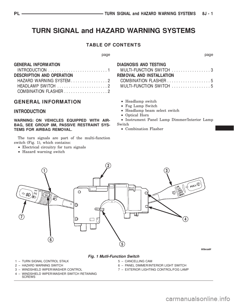
The turn signals are part of the multi-function
switch (Fig. 1), which contains:
²Electrical circuitry for turn signals
²Hazard warning switch²Headlamp switch
²Fog Lamp Switch
²Headlamp beam select switch
²Optical Horn
²Instrument Panel Lamp Dimmer/Interior Lamp
Switch
²Combination Flasher
Fig. 1 Mutli-Function Switch
1 ± TURN SIGNAL CONTROL STALK
2 ± HAZARD WARNING SWITCH
3 ± WINDSHIELD WIPER/WASHER CONTROL
4 ± WINDSHIELD WIPER/WASHER SWITCH RETAINING
SCREWS5 ± CANCELLING CAM
6 ± PANEL DIMMER/INTERIOR LIGHT SWITCH
7 ± EXTERIOR LIGHTING CONTROL/FOG LAMP
PLTURN SIGNAL and HAZARD WARNING SYSTEMS 8J - 1
Page 293 of 1285
The integrated switch assembly is mounted to the
left hand side of the steering column. When the
driver wishes to signal his intentions to change direc-
tion of travel, he moves the lever upward to cause
the right signals to flash and downward to cause the
left signals to flash. After completion of a turn the
system is deactivated automatically. As the steering
wheel returns to the straight ahead position, a can-
celing cam molded to the clockspring mechanism
comes in contact with the cancel actuator on the turn
signal multi-function switch assembly. The cam lobe,
pushing on the cancel actuator, returns the switch to
the off position.
If only momentary signaling such as indication of a
lane change is desired, the switch is actuated to a
left or right intermediate detent position. In this
position the signal lamps flash as described above,
but the switch returns to the OFF position as soon as
the lever is released.
When the system is activated, one of two indicator
lamps mounted in the instrument cluster flashes in
unison with the turn signal lamps, indicating to the
driver that the system is operating.
DESCRIPTION AND OPERATION
HAZARD WARNING SYSTEM
The hazard warning system is actuated by a push
button located in the muti-function switch (Fig. 1) on
the top of the steering column between the steering
wheel and the instrument panel. The hazard switch
is identified with a double triangle on front of the
button.
HEADLAMP SWITCH
The headlamp switch is part of the Multi-Function
Switch (Fig. 1). Refer to Multi-Function Switch Diag-
nosis and Testing, Turn Signal and Hazard Warning
Flasher Diagnosis table in this section.
COMBINATION FLASHER
The turn signal flasher and the hazard warning
flasher are combined into one unit called a combina-
tion flasher (combo-flasher). The combo- flasher con-
trols the flashing of the hazard warning system and
the turn signal system. An inoperative bulb or incom-
plete turn signal circuit will cause the flasher rate to
double.
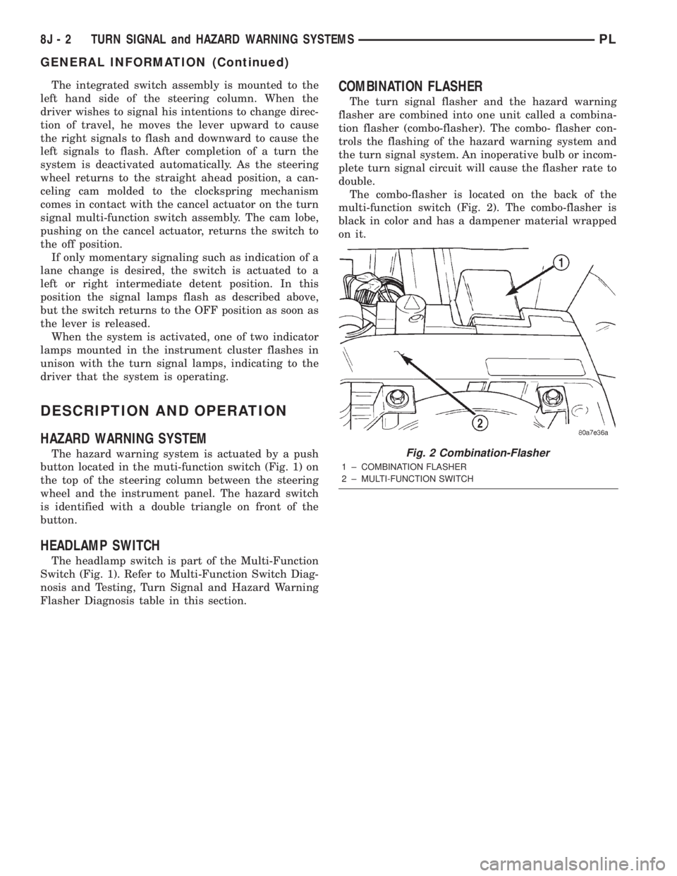
The combo-flasher is located on the back of the
multi-function switch (Fig. 2). The combo-flasher is
black in color and has a dampener material wrapped
on it.
Fig. 2 Combination-Flasher
1 ± COMBINATION FLASHER
2 ± MULTI-FUNCTION SWITCH
8J - 2 TURN SIGNAL and HAZARD WARNING SYSTEMSPL
GENERAL INFORMATION (Continued)
Page 294 of 1285
DIAGNOSIS AND TESTING
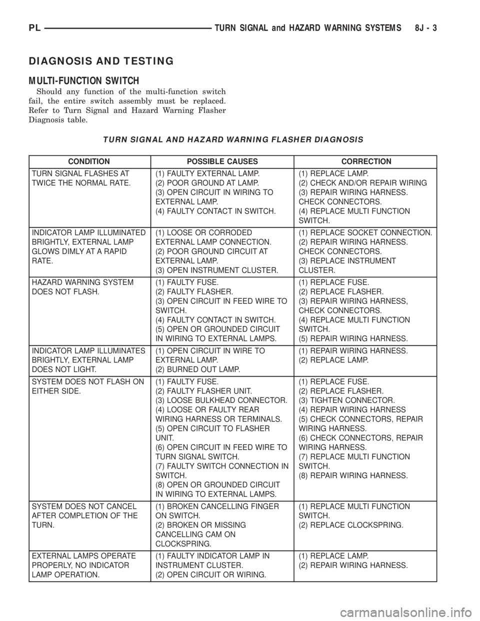
MULTI-FUNCTION SWITCH
Should any function of the multi-function switch
fail, the entire switch assembly must be replaced.
Refer to Turn Signal and Hazard Warning Flasher
Diagnosis table.
TURN SIGNAL AND HAZARD WARNING FLASHER DIAGNOSIS
CONDITION POSSIBLE CAUSES CORRECTION
TURN SIGNAL FLASHES AT
TWICE THE NORMAL RATE.(1) FAULTY EXTERNAL LAMP.
(2) POOR GROUND AT LAMP.
(3) OPEN CIRCUIT IN WIRING TO
EXTERNAL LAMP.
(4) FAULTY CONTACT IN SWITCH.(1) REPLACE LAMP.
(2) CHECK AND/OR REPAIR WIRING
(3) REPAIR WIRING HARNESS.
CHECK CONNECTORS.
(4) REPLACE MULTI FUNCTION
SWITCH.
INDICATOR LAMP ILLUMINATED
BRIGHTLY, EXTERNAL LAMP
GLOWS DIMLY AT A RAPID
RATE.(1) LOOSE OR CORRODED
EXTERNAL LAMP CONNECTION.
(2) POOR GROUND CIRCUIT AT
EXTERNAL LAMP.
(3) OPEN INSTRUMENT CLUSTER.(1) REPLACE SOCKET CONNECTION.
(2) REPAIR WIRING HARNESS.
CHECK CONNECTORS.
(3) REPLACE INSTRUMENT
CLUSTER.
HAZARD WARNING SYSTEM
DOES NOT FLASH.(1) FAULTY FUSE.
(2) FAULTY FLASHER.
(3) OPEN CIRCUIT IN FEED WIRE TO
SWITCH.
(4) FAULTY CONTACT IN SWITCH.
(5) OPEN OR GROUNDED CIRCUIT
IN WIRING TO EXTERNAL LAMPS.(1) REPLACE FUSE.
(2) REPLACE FLASHER.
(3) REPAIR WIRING HARNESS,
CHECK CONNECTORS.
(4) REPLACE MULTI FUNCTION
SWITCH.
(5) REPAIR WIRING HARNESS.
INDICATOR LAMP ILLUMINATES
BRIGHTLY, EXTERNAL LAMP
DOES NOT LIGHT.(1) OPEN CIRCUIT IN WIRE TO
EXTERNAL LAMP.
(2) BURNED OUT LAMP.(1) REPAIR WIRING HARNESS.
(2) REPLACE LAMP.
SYSTEM DOES NOT FLASH ON
EITHER SIDE.(1) FAULTY FUSE.
(2) FAULTY FLASHER UNIT.
(3) LOOSE BULKHEAD CONNECTOR.
(4) LOOSE OR FAULTY REAR
WIRING HARNESS OR TERMINALS.
(5) OPEN CIRCUIT TO FLASHER
UNIT.
(6) OPEN CIRCUIT IN FEED WIRE TO
TURN SIGNAL SWITCH.
(7) FAULTY SWITCH CONNECTION IN
SWITCH.
(8) OPEN OR GROUNDED CIRCUIT
IN WIRING TO EXTERNAL LAMPS.(1) REPLACE FUSE.
(2) REPLACE FLASHER.
(3) TIGHTEN CONNECTOR.
(4) REPAIR WIRING HARNESS
(5) CHECK CONNECTORS, REPAIR
WIRING HARNESS.
(6) CHECK CONNECTORS, REPAIR
WIRING HARNESS.
(7) REPLACE MULTI FUNCTION
SWITCH.
(8) REPAIR WIRING HARNESS.
SYSTEM DOES NOT CANCEL
AFTER COMPLETION OF THE
TURN.(1) BROKEN CANCELLING FINGER
ON SWITCH.
(2) BROKEN OR MISSING
CANCELLING CAM ON
CLOCKSPRING.(1) REPLACE MULTI FUNCTION
SWITCH.
(2) REPLACE CLOCKSPRING.
EXTERNAL LAMPS OPERATE
PROPERLY, NO INDICATOR
LAMP OPERATION.(1) FAULTY INDICATOR LAMP IN
INSTRUMENT CLUSTER.
(2) OPEN CIRCUIT OR WIRING.(1) REPLACE LAMP.
(2) REPAIR WIRING HARNESS.
PLTURN SIGNAL and HAZARD WARNING SYSTEMS 8J - 3
Page 295 of 1285
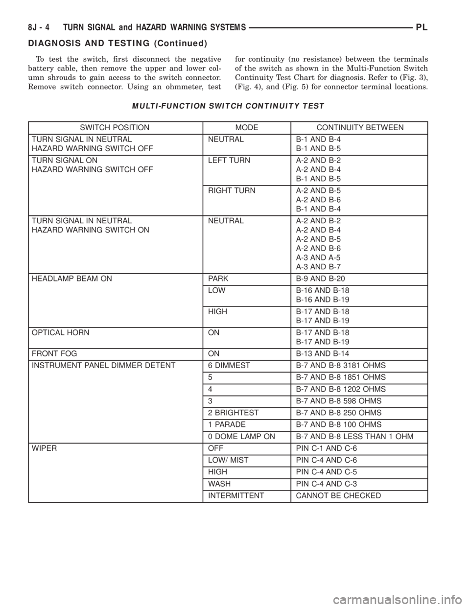
To test the switch, first disconnect the negative
battery cable, then remove the upper and lower col-
umn shrouds to gain access to the switch connector.
Remove switch connector. Using an ohmmeter, testfor continuity (no resistance) between the terminals
of the switch as shown in the Multi-Function Switch
Continuity Test Chart for diagnosis. Refer to (Fig. 3),
(Fig. 4), and (Fig. 5) for connector terminal locations.
MULTI-FUNCTION SWITCH CONTINUITY TEST
SWITCH POSITION MODE CONTINUITY BETWEEN
TURN SIGNAL IN NEUTRAL
HAZARD WARNING SWITCH OFFNEUTRAL B-1 AND B-4
B-1 AND B-5
TURN SIGNAL ON
HAZARD WARNING SWITCH OFFLEFT TURN A-2 AND B-2
A-2 AND B-4
B-1 AND B-5
RIGHT TURN A-2 AND B-5
A-2 AND B-6
B-1 AND B-4
TURN SIGNAL IN NEUTRAL
HAZARD WARNING SWITCH ONNEUTRAL A-2 AND B-2
A-2 AND B-4
A-2 AND B-5
A-2 AND B-6
A-3 AND A-5
A-3 AND B-7
HEADLAMP BEAM ON PARK B-9 AND B-20
LOW B-16 AND B-18
B-16 AND B-19
HIGH B-17 AND B-18
B-17 AND B-19
OPTICAL HORN ON B-17 AND B-18
B-17 AND B-19
FRONT FOG ON B-13 AND B-14
INSTRUMENT PANEL DIMMER DETENT 6 DIMMEST B-7 AND B-8 3181 OHMS
5 B-7 AND B-8 1851 OHMS
4 B-7 AND B-8 1202 OHMS
3 B-7 AND B-8 598 OHMS
2 BRIGHTEST B-7 AND B-8 250 OHMS
1 PARADE B-7 AND B-8 100 OHMS
0 DOME LAMP ON B-7 AND B-8 LESS THAN 1 OHM
WIPER OFF PIN C-1 AND C-6
LOW/ MIST PIN C-4 AND C-6
HIGH PIN C-4 AND C-5
WASH PIN C-4 AND C-3
INTERMITTENT CANNOT BE CHECKED
8J - 4 TURN SIGNAL and HAZARD WARNING SYSTEMSPL
DIAGNOSIS AND TESTING (Continued)
Page 296 of 1285
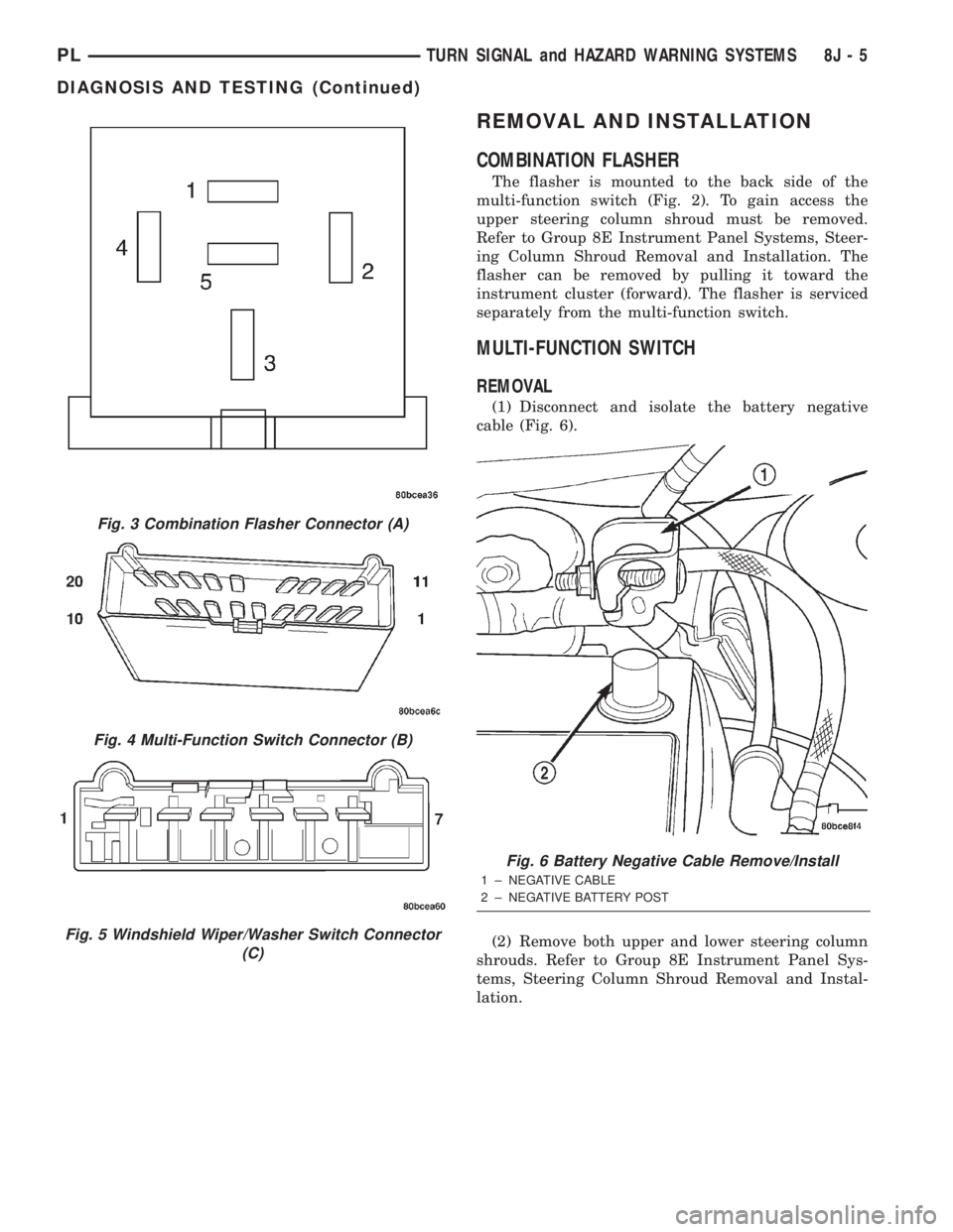
REMOVAL AND INSTALLATION
COMBINATION FLASHER
The flasher is mounted to the back side of the
multi-function switch (Fig. 2). To gain access the
upper steering column shroud must be removed.
Refer to Group 8E Instrument Panel Systems, Steer-
ing Column Shroud Removal and Installation. The
flasher can be removed by pulling it toward the
instrument cluster (forward). The flasher is serviced
separately from the multi-function switch.
MULTI-FUNCTION SWITCH
REMOVAL
(1) Disconnect and isolate the battery negative
cable (Fig. 6).
(2) Remove both upper and lower steering column
shrouds. Refer to Group 8E Instrument Panel Sys-
tems, Steering Column Shroud Removal and Instal-
lation.
Fig. 3 Combination Flasher Connector (A)
Fig. 4 Multi-Function Switch Connector (B)
Fig. 5 Windshield Wiper/Washer Switch Connector
(C)
Fig. 6 Battery Negative Cable Remove/Install
1 ± NEGATIVE CABLE
2 ± NEGATIVE BATTERY POST
PLTURN SIGNAL and HAZARD WARNING SYSTEMS 8J - 5
DIAGNOSIS AND TESTING (Continued)
Page 297 of 1285
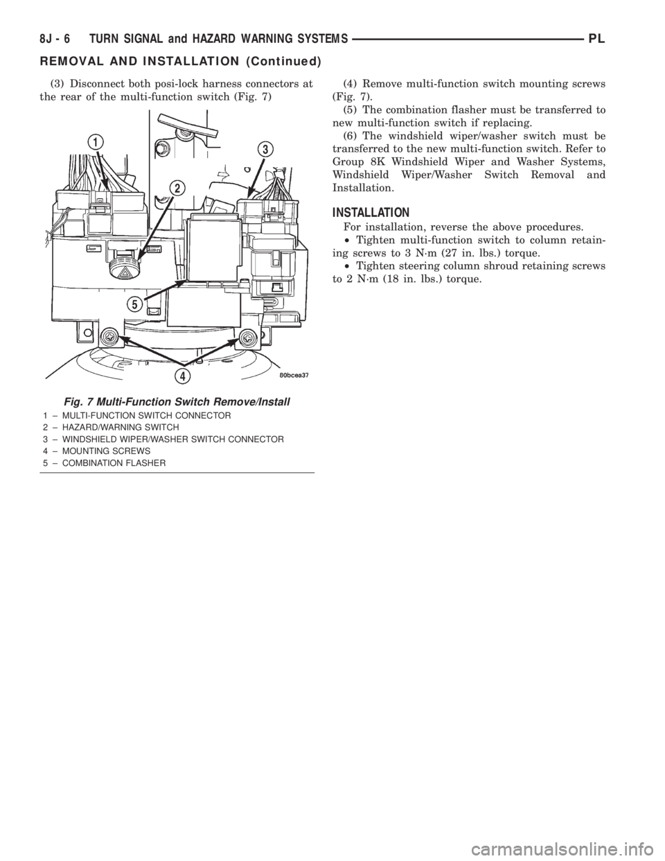
(3) Disconnect both posi-lock harness connectors at
the rear of the multi-function switch (Fig. 7)(4) Remove multi-function switch mounting screws
(Fig. 7).
(5) The combination flasher must be transferred to
new multi-function switch if replacing.
(6) The windshield wiper/washer switch must be
transferred to the new multi-function switch. Refer to
Group 8K Windshield Wiper and Washer Systems,
Windshield Wiper/Washer Switch Removal and
Installation.
INSTALLATION
For installation, reverse the above procedures.
²Tighten multi-function switch to column retain-
ing screws to 3 N´m (27 in. lbs.) torque.
²Tighten steering column shroud retaining screws
to 2 N´m (18 in. lbs.) torque.
Fig. 7 Multi-Function Switch Remove/Install
1 ± MULTI-FUNCTION SWITCH CONNECTOR
2 ± HAZARD/WARNING SWITCH
3 ± WINDSHIELD WIPER/WASHER SWITCH CONNECTOR
4 ± MOUNTING SCREWS
5 ± COMBINATION FLASHER
8J - 6 TURN SIGNAL and HAZARD WARNING SYSTEMSPL
REMOVAL AND INSTALLATION (Continued)
Page 303 of 1285
WINDSHIELD WIPER MODULE
REMOVAL
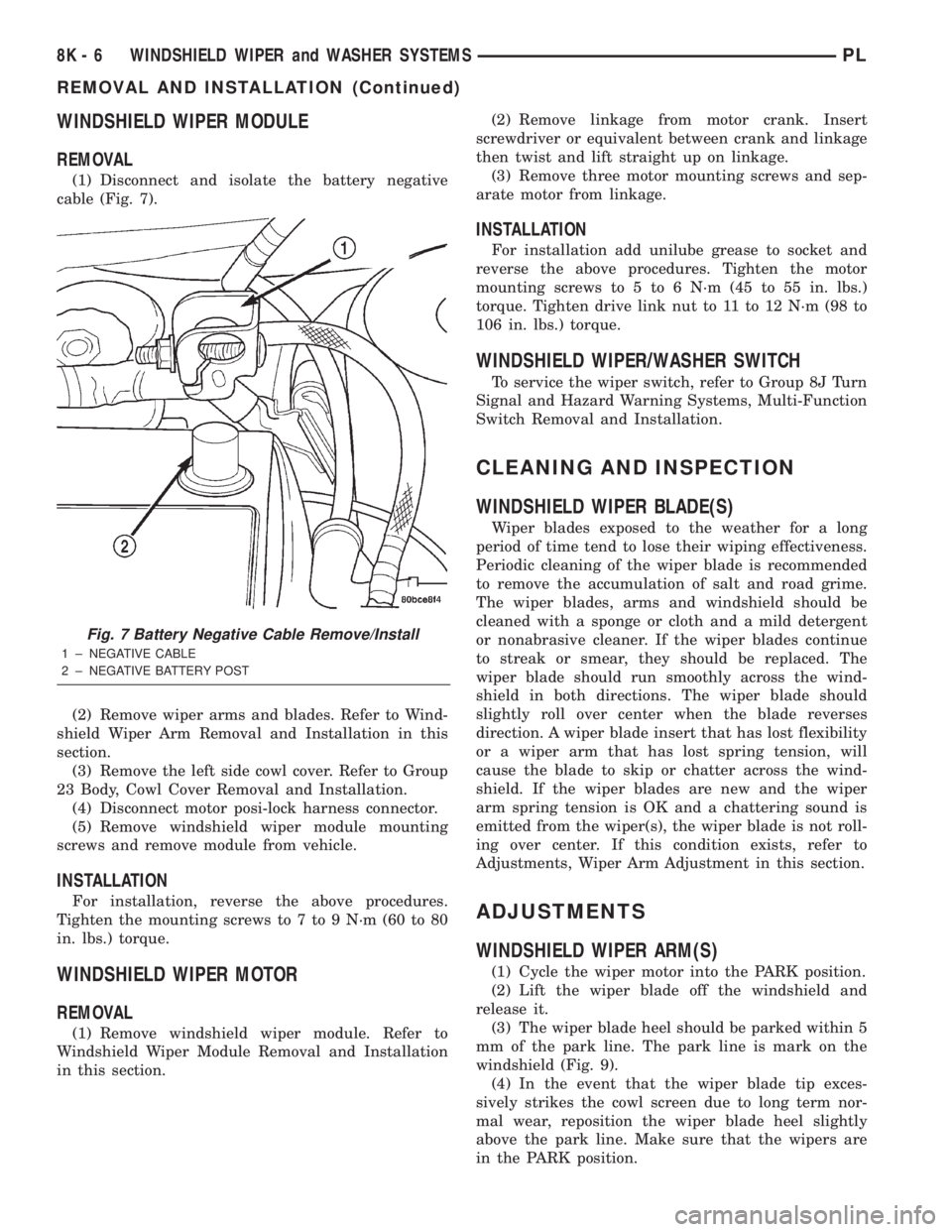
(1) Disconnect and isolate the battery negative
cable (Fig. 7).
(2) Remove wiper arms and blades. Refer to Wind-
shield Wiper Arm Removal and Installation in this
section.
(3) Remove the left side cowl cover. Refer to Group
23 Body, Cowl Cover Removal and Installation.
(4) Disconnect motor posi-lock harness connector.
(5) Remove windshield wiper module mounting
screws and remove module from vehicle.
INSTALLATION
For installation, reverse the above procedures.
Tighten the mounting screws to 7 to 9 N´m (60 to 80
in. lbs.) torque.
WINDSHIELD WIPER MOTOR
REMOVAL
(1) Remove windshield wiper module. Refer to
Windshield Wiper Module Removal and Installation
in this section.(2) Remove linkage from motor crank. Insert
screwdriver or equivalent between crank and linkage
then twist and lift straight up on linkage.
(3) Remove three motor mounting screws and sep-
arate motor from linkage.
INSTALLATION
For installation add unilube grease to socket and
reverse the above procedures. Tighten the motor
mounting screws to 5 to 6 N´m (45 to 55 in. lbs.)
torque. Tighten drive link nut to 11 to 12 N´m (98 to
106 in. lbs.) torque.
WINDSHIELD WIPER/WASHER SWITCH
To service the wiper switch, refer to Group 8J Turn
Signal and Hazard Warning Systems, Multi-Function
Switch Removal and Installation.
CLEANING AND INSPECTION
WINDSHIELD WIPER BLADE(S)
Wiper blades exposed to the weather for a long
period of time tend to lose their wiping effectiveness.
Periodic cleaning of the wiper blade is recommended
to remove the accumulation of salt and road grime.
The wiper blades, arms and windshield should be
cleaned with a sponge or cloth and a mild detergent
or nonabrasive cleaner. If the wiper blades continue
to streak or smear, they should be replaced. The
wiper blade should run smoothly across the wind-
shield in both directions. The wiper blade should
slightly roll over center when the blade reverses
direction. A wiper blade insert that has lost flexibility
or a wiper arm that has lost spring tension, will
cause the blade to skip or chatter across the wind-
shield. If the wiper blades are new and the wiper
arm spring tension is OK and a chattering sound is
emitted from the wiper(s), the wiper blade is not roll-
ing over center. If this condition exists, refer to
Adjustments, Wiper Arm Adjustment in this section.
ADJUSTMENTS
WINDSHIELD WIPER ARM(S)
(1) Cycle the wiper motor into the PARK position.
(2) Lift the wiper blade off the windshield and
release it.
(3) The wiper blade heel should be parked within 5
mm of the park line. The park line is mark on the
windshield (Fig. 9).
(4) In the event that the wiper blade tip exces-
sively strikes the cowl screen due to long term nor-
mal wear, reposition the wiper blade heel slightly
above the park line. Make sure that the wipers are
in the PARK position.
Fig. 7 Battery Negative Cable Remove/Install
1 ± NEGATIVE CABLE
2 ± NEGATIVE BATTERY POST
8K - 6 WINDSHIELD WIPER and WASHER SYSTEMSPL
REMOVAL AND INSTALLATION (Continued)