2000 DODGE NEON sensor
[x] Cancel search: sensorPage 286 of 1285
VEHICLE SPEED CONTROL SYSTEM
TABLE OF CONTENTS
page page
DESCRIPTION AND OPERATION
SPEED CONTROL SYSTEM.................1
SPEED CONTROL SERVO-PCM OUTPUT.......2
SPEED CONTROL SWITCHESÐPCM INPUT....2
STOP LAMP SWITCH......................3
SERVO CABLE...........................3
VACUUM RESERVOIR.....................3VEHICLE SPEED SENSOR..................3
REMOVAL AND INSTALLATION
SPEED CONTROL SERVO...................3
SPEED CONTROL SWITCH..................4
SPEED CONTROL SERVO CABLE.............4
VACUUM RESERVOIR.....................5
DESCRIPTION AND OPERATION
SPEED CONTROL SYSTEM
OPERATION
The speed control system is electronically con-
trolled and vacuum operated. The electronic control
is integrated into the Powertrain Control Module
which is located in the engine compartment. The con-
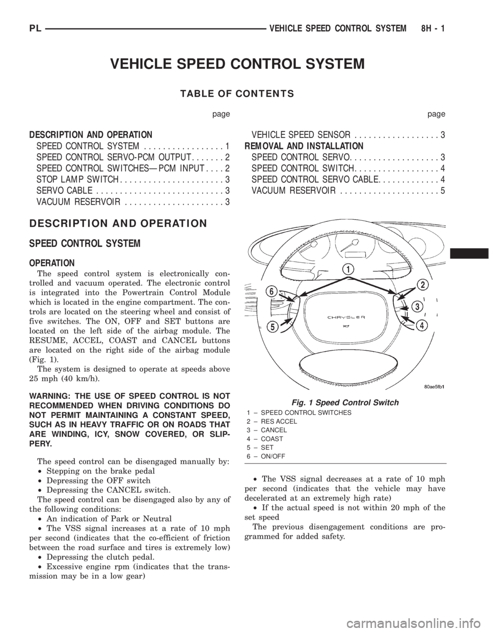
trols are located on the steering wheel and consist of
five switches. The ON, OFF and SET buttons are
located on the left side of the airbag module. The
RESUME, ACCEL, COAST and CANCEL buttons
are located on the right side of the airbag module
(Fig. 1).
The system is designed to operate at speeds above
25 mph (40 km/h).
WARNING: THE USE OF SPEED CONTROL IS NOT
RECOMMENDED WHEN DRIVING CONDITIONS DO
NOT PERMIT MAINTAINING A CONSTANT SPEED,
SUCH AS IN HEAVY TRAFFIC OR ON ROADS THAT
ARE WINDING, ICY, SNOW COVERED, OR SLIP-
PERY.
The speed control can be disengaged manually by:
²Stepping on the brake pedal
²Depressing the OFF switch
²Depressing the CANCEL switch.
The speed control can be disengaged also by any of
the following conditions:
²An indication of Park or Neutral
²The VSS signal increases at a rate of 10 mph
per second (indicates that the co-efficient of friction
between the road surface and tires is extremely low)
²Depressing the clutch pedal.
²Excessive engine rpm (indicates that the trans-
mission may be in a low gear)²The VSS signal decreases at a rate of 10 mph
per second (indicates that the vehicle may have
decelerated at an extremely high rate)
²If the actual speed is not within 20 mph of the
set speed
The previous disengagement conditions are pro-
grammed for added safety.
Fig. 1 Speed Control Switch
1 ± SPEED CONTROL SWITCHES
2 ± RES ACCEL
3 ± CANCEL
4 ± COAST
5 ± SET
6 ± ON/OFF
PLVEHICLE SPEED CONTROL SYSTEM 8H - 1
Page 288 of 1285
On most vehicles another resistor has been added
to the at rest circuit causing the PCM to never see 5
volts. This was done for diagnostic purposes. If the
switch circuit should open (bad connection) then the
PCM will see the 5 volts and know the circuit is bad.
The PCM will then set an open circuit fault.
STOP LAMP SWITCH
DESCRIPTION
The switch is mounted on the brake pedal mount-
ing bracket under the instrument panel.
OPERATION
Vehicles equipped with the speed control option use
a dual function stop lamp switch. The PCM monitors
the state of the dual function stop lamp switch. Refer
to the Brake section for more information on stop
lamp switch service and adjustment procedures.
The brake switch is equipped with three sets of
contacts, one normally open and the other two nor-
mally closed (brakes disengaged). The PCM sends a
12 volt signal to one of the normally closed contacts
in the brake switch, which is connected to a ground.
With the contacts closed, the 12 volt signal is pulled
to ground causing the signal to go low. The low volt-
age signal, monitored by the PCM, indicates that the
brakes are not applied. When the brakes are applied,
the contacts open, causing the PCM's output voltage
to go high, disengaging the speed control also
grounding the dump solenoid.
The second set of normally closed contacts is sup-
plied battery voltage any time speed control is
selected. From the brake switch, current is routed to
the speed control servo solenoids. The speed control
solenoids (vacuum, vent and dump) are provided this
current any time the speed control is ON and the
brakes are disengaged. When the driver applies the
brakes, the contacts open and current is interrupted
to the solenoids. The normally open contacts are fed
battery voltage. When the brakes are applied, battery
voltage is supplied to the stop lamps.
SERVO CABLE
DESCRIPTION
The speed control servo cable is connected between
the speed control vacuum servo diaphragm and the
throttle body control linkage.
OPERATION
This cable causes the throttle control linkage to
open or close the throttle valve in response to move-
ment of the vacuum servo diaphragm.
VACUUM RESERVOIR
OPERATION
The reservoir stores engine vacuum in the reser-
voir. When engine vacuum drops, as in climbing a
grade while driving, the reservoir supplies the vac-
uum needed to maintain proper speed control opera-
tion. The vacuum reservoir cannot be repaired and
must be replaced if faulty.
VEHICLE SPEED SENSOR
The Vehicle Speed Sensor (VSS) is a pulse genera-
tor mounted to an adapter near the transmission out-
put shaft. The sensor is driven through the adapter
by a speedometer pinion gear. The VSS pulse signal
to the speedometer/odometer is monitored by the
PCM speed control circuitry to determine vehicle
speed and to maintain speed control set speed.
REMOVAL AND INSTALLATION
SPEED CONTROL SERVO
REMOVAL
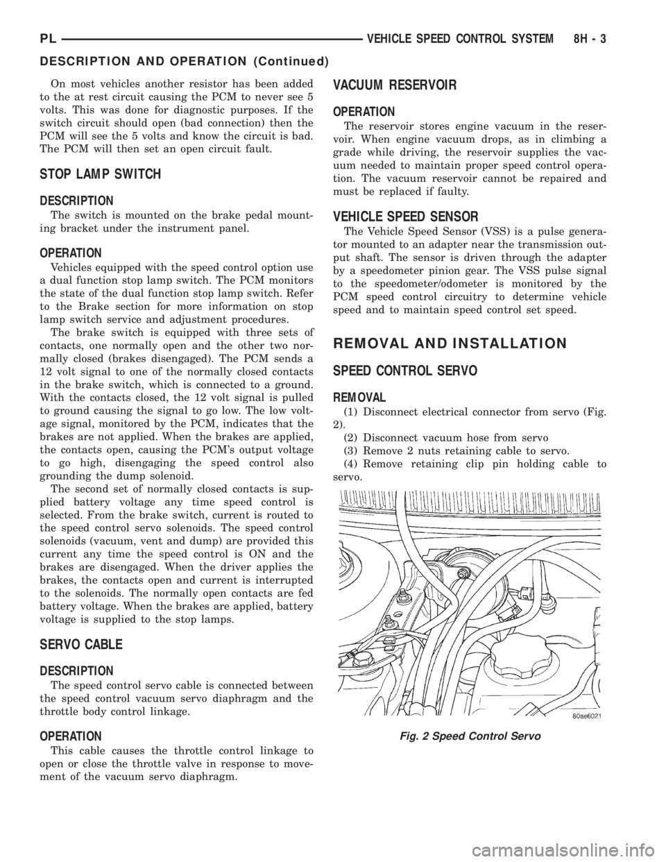
(1) Disconnect electrical connector from servo (Fig.
2).
(2) Disconnect vacuum hose from servo
(3) Remove 2 nuts retaining cable to servo.
(4) Remove retaining clip pin holding cable to
servo.
Fig. 2 Speed Control Servo
PLVEHICLE SPEED CONTROL SYSTEM 8H - 3
DESCRIPTION AND OPERATION (Continued)
Page 346 of 1285
PASSIVE RESTRAINT SYSTEMS
TABLE OF CONTENTS
page page
GENERAL INFORMATION
WARNINGS AND PRECAUTIONS.............1
DESCRIPTION AND OPERATION
AIRBAG CONTROL MODULE (ACM)..........1
CLOCKSPRING...........................2
DRIVER and PASSENGER AIRBAG MODULE....2
DIAGNOSIS AND TESTING
AIRBAG SYSTEM.........................3
SERVICE PROCEDURES
CLEAN UP PROCEDURE....................3HANDLING AIRBAG MODULES..............4
MAINTENANCE INSPECTION................4
REMOVAL AND INSTALLATION
AIRBAG CONTROL MODULE (ACM)..........4
CLOCKSPRING...........................5
DRIVER AIRBAG MODULE..................6
PASSENGER AIRBAG MODULE..............7
STEERING WHEEL........................8
ADJUSTMENTS
CLOCKSPRING CENTERING PROCEDURE......9
GENERAL INFORMATION
WARNINGS AND PRECAUTIONS
WARNING: THIS SYSTEM IS A SENSITIVE, COM-
PLEX ELECTRO±MECHANICAL UNIT. DISCONNECT
AND ISOLATE THE BATTERY NEGATIVE CABLE
BEFORE BEGINNING AIRBAG SYSTEM COMPO-
NENT REMOVAL OR INSTALLATION PROCEDURES.
THIS WILL DISABLE THE AIRBAG SYSTEM. FAIL-
URE TO DISCONNECT THE BATTERY COULD
RESULT IN ACCIDENTAL AIRBAG DEPLOYMENT
AND POSSIBLE PERSONAL INJURY.
ALLOW SYSTEM CAPACITOR TO DISCHARGE
FOR ONE MINUTE BEFORE REMOVING AIRBAG
COMPONENTS.
DO NOT PLACE AN INTACT UNDEPLOYED AIRBAG
FACE DOWN ON A SOLID SURFACE, THE AIRBAG
WILL PROPEL INTO THE AIR IF ACCIDENTALLY
DEPLOYED AND COULD RESULT IN PERSONAL
INJURY. WHEN CARRYING OR HANDLING AN UNDE-
PLOYED AIRBAG MODULE, THE TRIM SIDE OF THE
AIRBAG SHOULD BE POINTING AWAY FROM THE
BODY TO MINIMIZE POSSIBILITY OF INJURY IF ACCI-
DENTAL DEPLOYMENT OCCURS.
REPLACE AIRBAG SYSTEM COMPONENTS WITH
MOPARTREPLACEMENT PARTS. SUBSTITUTE
PARTS MAY APPEAR INTERCHANGEABLE, BUT
INTERNAL DIFFERENCES MAY RESULT IN INFE-
RIOR OCCUPANT PROTECTION.
WEAR SAFETY GLASSES, RUBBER GLOVES,
AND LONG SLEEVES CLOTHING WHEN CLEANING
POWDER RESIDUE FROM VEHICLE AFTER AIRBAG
DEPLOYMENT. SODIUM HYDROXIDE POWDER
RESIDUE EMITTED FROM A DEPLOYED AIRBAG
CAN CAUSE SKIN IRRITATION. FLUSH AFFECTEDAREA WITH COOL WATER IF IRRITATION IS EXPE-
RIENCED. IF NASAL OR THROAT IRRITATION IS
EXPERIENCED, EXIT THE VEHICLE FOR FRESH AIR
UNTIL THE IRRITATION CEASES. IF IRRITATION
CONTINUES, SEE A PHYSICIAN.
DO NOT USE A REPLACEMENT AIRBAG THAT IS
NOT IN THE ORIGINAL PACKAGING, IMPROPER
DEPLOYMENT AND PERSONAL INJURY CAN
RESULT.
THE FACTORY INSTALLED FASTENERS,
SCREWS AND BOLTS USED TO FASTEN AIRBAG
COMPONENTS HAVE A SPECIAL COATING AND
ARE SPECIFICALLY DESIGNED FOR THE AIRBAG
SYSTEM. DO NOT USE SUBSTITUTE FASTENERS,
USE ONLY ORIGINAL EQUIPMENT FASTENERS
LISTED IN THE PARTS CATALOG WHEN FASTENER
REPLACEMENT IS REQUIRED.
NOTE: Airbags should be stored in a cool dry loca-
tion away from excessive heat and static electrical
activity with the fabric airbag facing UP, or a prema-
ture deployment can result.
If the Driver/Passenger Airbag Module is defective
and not deployed, refer to DaimlerChrysler Corpora-
tion current return list for proper handling proce-
dures.
DESCRIPTION AND OPERATION
AIRBAG CONTROL MODULE (ACM)
The Airbag Control Module (ACM) contains the
sensing element, safing sensor, and energy reserve
capacitor. The module is mounted on the tunnel/floor
pan between the gear shift lever and the park brake
PLPASSIVE RESTRAINT SYSTEMS 8M - 1
Page 349 of 1285
²Clockspring assembly
²Steering Column Assembly w/Lower Steering
Column Coupler
PASSENGER AIRBAG
After a Passenger Airbag Module has been
deployed, replace the following components because
they cannot be reused.
²Passenger Airbag Module
Inspect all the attaching hardware and instrument
panel for damage. If damage is evident, components
should be replaced.
HANDLING AIRBAG MODULES
DEPLOYED AIRBAG MODULE
The vehicle interior may contain a very small
amount of sodium hydroxide powder, a by-product of
airbag deployment. Sodium hydroxide powder can
irritate the skin, eyes, nose and throat. Wear safety
glasses, rubber gloves, and long sleeved clothing
when cleaning any of the powder residue from the
vehicle.
If you find that the cleanup is irritating your skin,
run cool water over the affected area. Also, if you
experience nasal or throat irritation, exit the vehicle
for fresh air until the irritation ceases. If irritation
continues, see a physician.
UNDEPLOYED AIRBAG MODULE
The airbag modules must be stored in its original
special container until used for service. At no time
should a source of electricity be permitted near the
inflator on the back of an airbag module. When car-
rying or handling an undeployed airbag module, the
trim side of the airbag should be pointing away from
the body to minimize possibility of injury if acciden-
tal deployment occurs. Do not place undeployed air-
bag face down on a solid surface, the airbag will
propel into the air if accidentally deployment occurs.
MAINTENANCE INSPECTION
(1) Check the airbag warning lamp for proper
operation as follows:
(a) Turn ignition switch to the ON position, the
airbag warning lamp should light. If not, test the
system using a DRB llltscan tool and the proper
Body Diagnostic Procedures Manual.
(b) The airbag warning lamp lights, but fails to
go out after eight seconds. Test the system using a
DRB llltscan tool and the proper Body Diagnostic
Procedures Manual.
(c) After correcting active malfunction erase
stored Diagnostic Trouble Codes (DTC's).
REMOVAL AND INSTALLATION
AIRBAG CONTROL MODULE (ACM)
WARNING: THE ACM CONTAINS THE SENSING
ELEMENT AND A SAFING SENSOR WHICH
ENABLES THE SYSTEM TO DEPLOY THE AIR-
BAGS. TO AVOID ACCIDENTAL DEPLOYMENT,
NEVER CONNECT ACM ELECTRICALLY TO THE
SYSTEM WHILE VEHICLE BATTERY IS CON-
NECTED.
DISCONNECT AND ISOLATE THE BATTERY NEG-
ATIVE (GROUND) CABLE BEFORE BEGINNING ANY
AIRBAG SYSTEM COMPONENT REMOVAL OR
INSTALLATION PROCEDURE. THIS WILL DISABLE
THE AIRBAG SYSTEM. FAILURE TO DISCONNECT
BATTERY COULD RESULT IN ACCIDENTAL AIRBAG
DEPLOYMENT AND POSSIBLE PERSONAL INJURY.
ALLOW SYSTEM CAPACITOR TO DISCHARGE
FOR 1 MINUTE BEFORE REMOVING ANY AIRBAG
COMPONENTS.
REMOVAL
(1) Disconnect and isolate the battery negative
cable (Fig. 4).
(2) Remove center console. Refer to Group 23 Body,
Floor Console Removal and Installation.
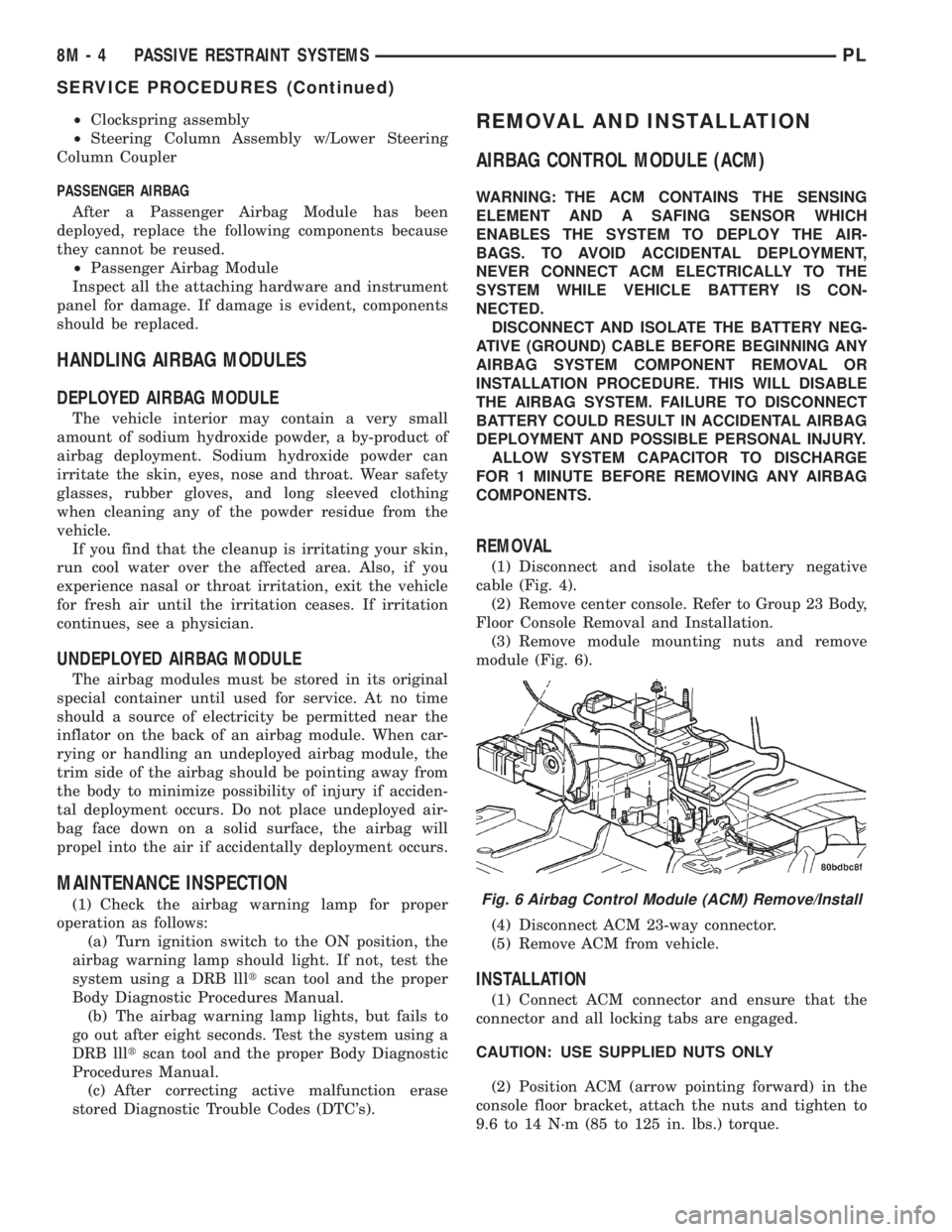
(3) Remove module mounting nuts and remove
module (Fig. 6).
(4) Disconnect ACM 23-way connector.
(5) Remove ACM from vehicle.
INSTALLATION
(1) Connect ACM connector and ensure that the
connector and all locking tabs are engaged.
CAUTION: USE SUPPLIED NUTS ONLY
(2) Position ACM (arrow pointing forward) in the
console floor bracket, attach the nuts and tighten to
9.6 to 14 N´m (85 to 125 in. lbs.) torque.
Fig. 6 Airbag Control Module (ACM) Remove/Install
8M - 4 PASSIVE RESTRAINT SYSTEMSPL
SERVICE PROCEDURES (Continued)
Page 365 of 1285
first turn) will cause all vehicle doors to unlock elec-
trically. When this feature is disabled, all vehicle
doors will be unlocked electrically upon the first turn
of a key cylinder to the UNLOCK position. The vehi-
cle is locked electrically by turning the key cylinder
to the LOCK position once, regardless of the state of
the double activation unlock feature.
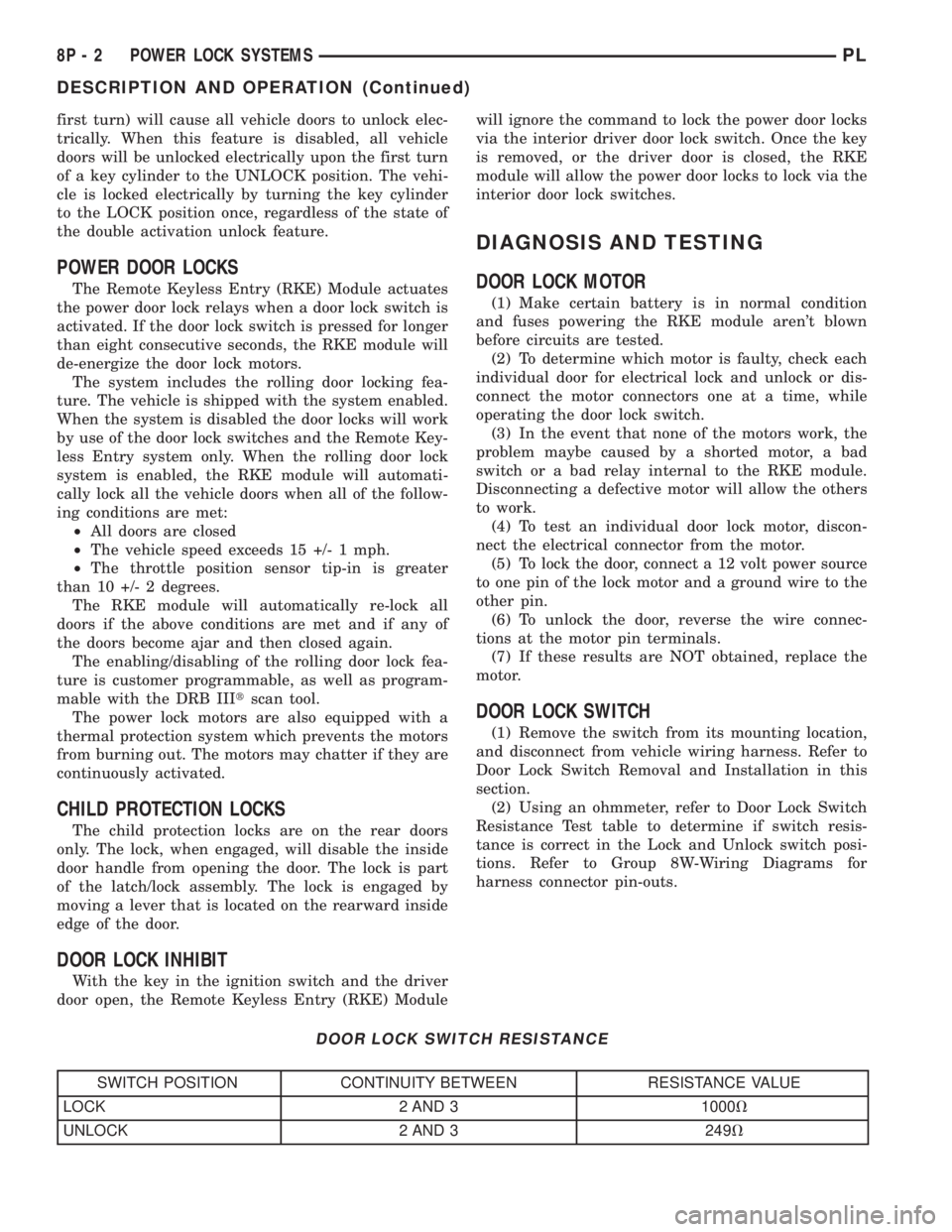
POWER DOOR LOCKS
The Remote Keyless Entry (RKE) Module actuates
the power door lock relays when a door lock switch is
activated. If the door lock switch is pressed for longer
than eight consecutive seconds, the RKE module will
de-energize the door lock motors.
The system includes the rolling door locking fea-
ture. The vehicle is shipped with the system enabled.
When the system is disabled the door locks will work
by use of the door lock switches and the Remote Key-
less Entry system only. When the rolling door lock
system is enabled, the RKE module will automati-
cally lock all the vehicle doors when all of the follow-
ing conditions are met:
²All doors are closed
²The vehicle speed exceeds 15 +/- 1 mph.
²The throttle position sensor tip-in is greater
than 10 +/- 2 degrees.
The RKE module will automatically re-lock all
doors if the above conditions are met and if any of
the doors become ajar and then closed again.
The enabling/disabling of the rolling door lock fea-
ture is customer programmable, as well as program-
mable with the DRB IIItscan tool.
The power lock motors are also equipped with a
thermal protection system which prevents the motors
from burning out. The motors may chatter if they are
continuously activated.
CHILD PROTECTION LOCKS
The child protection locks are on the rear doors
only. The lock, when engaged, will disable the inside
door handle from opening the door. The lock is part
of the latch/lock assembly. The lock is engaged by
moving a lever that is located on the rearward inside
edge of the door.
DOOR LOCK INHIBIT
With the key in the ignition switch and the driver
door open, the Remote Keyless Entry (RKE) Modulewill ignore the command to lock the power door locks
via the interior driver door lock switch. Once the key
is removed, or the driver door is closed, the RKE
module will allow the power door locks to lock via the
interior door lock switches.
DIAGNOSIS AND TESTING
DOOR LOCK MOTOR
(1) Make certain battery is in normal condition
and fuses powering the RKE module aren't blown
before circuits are tested.
(2) To determine which motor is faulty, check each
individual door for electrical lock and unlock or dis-
connect the motor connectors one at a time, while
operating the door lock switch.
(3) In the event that none of the motors work, the
problem maybe caused by a shorted motor, a bad
switch or a bad relay internal to the RKE module.
Disconnecting a defective motor will allow the others
to work.
(4) To test an individual door lock motor, discon-
nect the electrical connector from the motor.
(5) To lock the door, connect a 12 volt power source
to one pin of the lock motor and a ground wire to the
other pin.
(6) To unlock the door, reverse the wire connec-
tions at the motor pin terminals.
(7) If these results are NOT obtained, replace the
motor.
DOOR LOCK SWITCH
(1) Remove the switch from its mounting location,
and disconnect from vehicle wiring harness. Refer to
Door Lock Switch Removal and Installation in this
section.
(2) Using an ohmmeter, refer to Door Lock Switch
Resistance Test table to determine if switch resis-
tance is correct in the Lock and Unlock switch posi-
tions. Refer to Group 8W-Wiring Diagrams for
harness connector pin-outs.
DOOR LOCK SWITCH RESISTANCE
SWITCH POSITION CONTINUITY BETWEEN RESISTANCE VALUE
LOCK 2 AND 3 1000V
UNLOCK 2 AND 3 249V
8P - 2 POWER LOCK SYSTEMSPL
DESCRIPTION AND OPERATION (Continued)
Page 410 of 1285
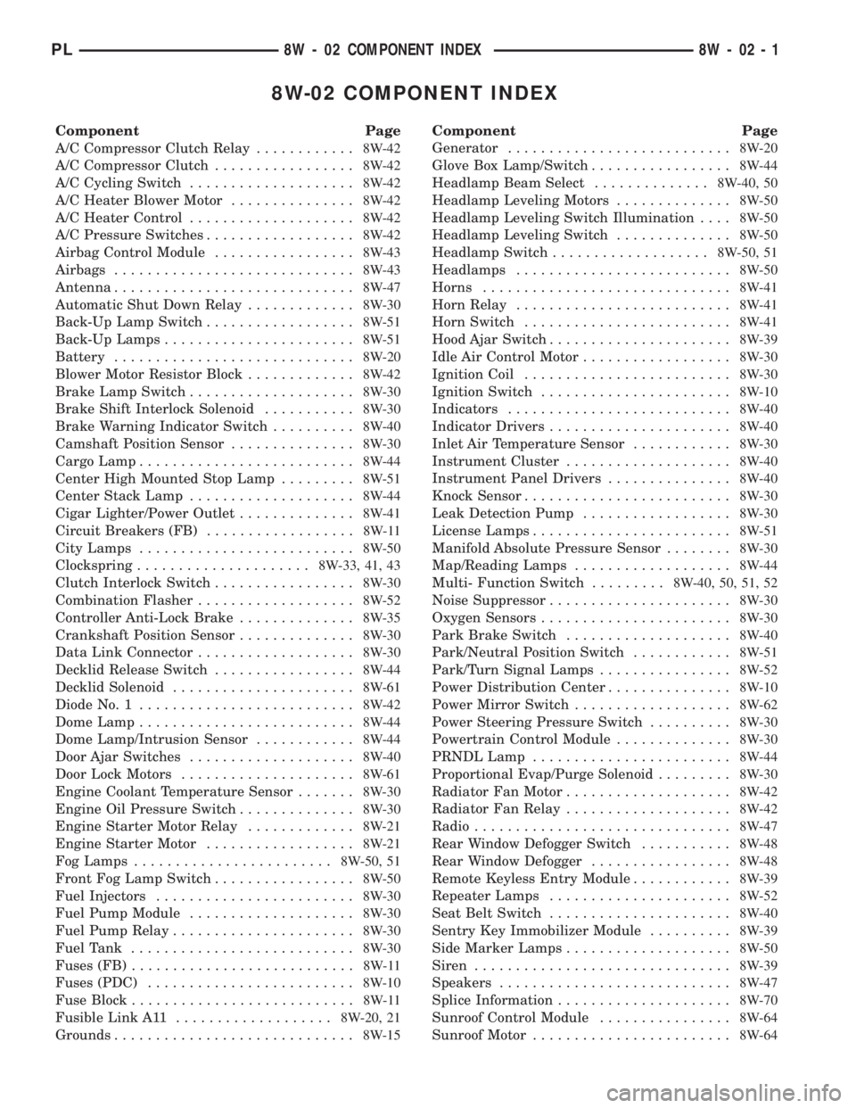
8W-02 COMPONENT INDEX
Component Page
A/C Compressor Clutch Relay............8W-42
A/C Compressor Clutch.................8W-42
A/C Cycling Switch....................8W-42
A/C Heater Blower Motor...............8W-42
A/C Heater Control....................8W-42
A/C Pressure Switches..................8W-42
Airbag Control Module.................8W-43
Airbags.............................8W-43
Antenna.............................8W-47
Automatic Shut Down Relay.............8W-30
Back-Up Lamp Switch..................8W-51
Back-Up Lamps.......................8W-51
Battery.............................8W-20
Blower Motor Resistor Block.............8W-42
Brake Lamp Switch....................8W-30
Brake Shift Interlock Solenoid...........8W-30
Brake Warning Indicator Switch..........8W-40
Camshaft Position Sensor...............8W-30
Cargo Lamp..........................8W-44
Center High Mounted Stop Lamp.........8W-51
Center Stack Lamp....................8W-44
Cigar Lighter/Power Outlet..............8W-41
Circuit Breakers (FB)..................8W-11
City Lamps..........................8W-50
Clockspring.....................8W-33, 41, 43
Clutch Interlock Switch.................8W-30
Combination Flasher...................8W-52
Controller Anti-Lock Brake..............8W-35
Crankshaft Position Sensor..............8W-30
Data Link Connector...................8W-30
Decklid Release Switch.................8W-44
Decklid Solenoid......................8W-61
Diode No. 1..........................8W-42
Dome Lamp..........................8W-44
Dome Lamp/Intrusion Sensor............8W-44
Door Ajar Switches....................8W-40
Door Lock Motors.....................8W-61
Engine Coolant Temperature Sensor.......8W-30
Engine Oil Pressure Switch..............8W-30
Engine Starter Motor Relay.............8W-21
Engine Starter Motor..................8W-21
Fog Lamps........................8W-50, 51
Front Fog Lamp Switch.................8W-50
Fuel Injectors........................8W-30
Fuel Pump Module....................8W-30
Fuel Pump Relay......................8W-30
Fuel Tank...........................8W-30
Fuses (FB)...........................8W-11
Fuses (PDC).........................8W-10
Fuse Block...........................8W-11
Fusible Link A11...................8W-20, 21
Grounds.............................8W-15Component Page
Generator...........................8W-20
Glove Box Lamp/Switch.................8W-44
Headlamp Beam Select..............8W-40, 50
Headlamp Leveling Motors..............8W-50
Headlamp Leveling Switch Illumination....8W-50
Headlamp Leveling Switch..............8W-50
Headlamp Switch...................8W-50, 51
Headlamps..........................8W-50
Horns..............................8W-41
Horn Relay..........................8W-41
Horn Switch.........................8W-41
Hood Ajar Switch......................8W-39
Idle Air Control Motor..................8W-30
Ignition Coil.........................8W-30
Ignition Switch.......................8W-10
Indicators...........................8W-40
Indicator Drivers......................8W-40
Inlet Air Temperature Sensor............8W-30
Instrument Cluster....................8W-40
Instrument Panel Drivers...............8W-40
Knock Sensor.........................8W-30
Leak Detection Pump..................8W-30
License Lamps........................8W-51
Manifold Absolute Pressure Sensor........8W-30
Map/Reading Lamps...................8W-44
Multi- Function Switch.........8W-40, 50, 51, 52
Noise Suppressor......................8W-30
Oxygen Sensors.......................8W-30
Park Brake Switch....................8W-40
Park/Neutral Position Switch............8W-51
Park/Turn Signal Lamps................8W-52
Power Distribution Center...............8W-10
Power Mirror Switch...................8W-62
Power Steering Pressure Switch..........8W-30
Powertrain Control Module..............8W-30
PRNDL Lamp........................8W-44
Proportional Evap/Purge Solenoid.........8W-30
Radiator Fan Motor....................8W-42
Radiator Fan Relay....................8W-42
Radio...............................8W-47
Rear Window Defogger Switch...........8W-48
Rear Window Defogger.................8W-48
Remote Keyless Entry Module............8W-39
Repeater Lamps......................8W-52
Seat Belt Switch......................8W-40
Sentry Key Immobilizer Module..........8W-39
Side Marker Lamps....................8W-50
Siren...............................8W-39
Speakers............................8W-47
Splice Information.....................8W-70
Sunroof Control Module................8W-64
Sunroof Motor........................8W-64
PL8W - 02 COMPONENT INDEX 8W - 02 - 1
Page 411 of 1285
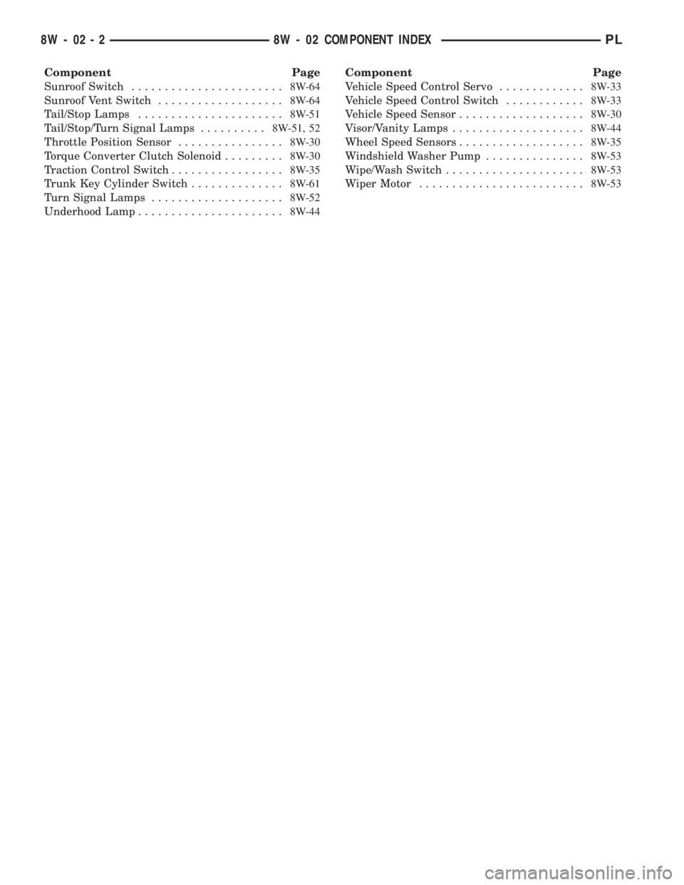
Component Page
Sunroof Switch.......................8W-64
Sunroof Vent Switch...................8W-64
Tail/Stop Lamps......................8W-51
Tail/Stop/Turn Signal Lamps..........8W-51, 52
Throttle Position Sensor................8W-30
Torque Converter Clutch Solenoid.........8W-30
Traction Control Switch.................8W-35
Trunk Key Cylinder Switch..............8W-61
Turn Signal Lamps....................8W-52
Underhood Lamp......................8W-44Component Page
Vehicle Speed Control Servo.............8W-33
Vehicle Speed Control Switch............8W-33
Vehicle Speed Sensor...................8W-30
Visor/Vanity Lamps....................8W-44
Wheel Speed Sensors...................8W-35
Windshield Washer Pump...............8W-53
Wipe/Wash Switch.....................8W-53
Wiper Motor.........................8W-53
8W - 02 - 2 8W - 02 COMPONENT INDEXPL
Page 412 of 1285
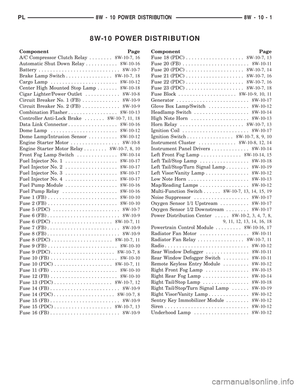
8W-10 POWER DISTRIBUTION
Component Page
A/C Compressor Clutch Relay........8W-10-7, 16
Automatic Shut Down Relay...........8W-10-16
Battery............................8W-10-7
Brake Lamp Switch................8W-10-7, 18
Cargo Lamp.......................8W-10-12
Center High Mounted Stop Lamp.......8W-10-18
Cigar Lighter/Power Outlet............8W-10-8
Circuit Breaker No. 1 (FB).............8W-10-9
Circuit Breaker No. 2 (FB).............8W-10-9
Combination Flasher.................8W-10-13
Controller Anti-Lock Brake.......8W-10-7, 11, 18
Data Link Connector.................8W-10-16
Dome Lamp.......................8W-10-12
Dome Lamp/Intrusion Sensor..........8W-10-12
Engine Starter Motor.................8W-10-8
Engine Starter Motor Relay........8W-10-7, 8, 10
Front Fog Lamp Switch..............8W-10-14
Fuel Injector No. 1..................8W-10-17
Fuel Injector No. 2..................8W-10-17
Fuel Injector No. 3..................8W-10-17
Fuel Injector No. 4..................8W-10-17
Fuel Pump Module..................8W-10-16
Fuel Pump Relay...................8W-10-16
Fuse 1 (FB)........................8W-10-10
Fuse 2 (FB)........................8W-10-10
Fuse 5 (PDC).......................8W-10-7
Fuse 6 (FB).........................8W-10-9
Fuse 6 (PDC).....................8W-10-7, 11
Fuse 7 (FB).........................8W-10-9
Fuse 8 (FB).........................8W-10-9
Fuse 8 (PDC).....................8W-10-7, 11
Fuse 9 (FB)........................8W-10-10
Fuse 9 (PDC)......................8W-10-7, 8
Fuse 10 (FB).......................8W-10-10
Fuse 10 (PDC)....................8W-10-7, 11
Fuse 11 (FB).......................8W-10-10
Fuse 12 (FB).......................8W-10-10
Fuse 13 (PDC)....................8W-10-7, 12
Fuse 14 (FB)........................8W-10-9
Fuse 14 (PDC).....................8W-10-7, 8
Fuse 15 (FB)........................8W-10-9
Fuse 15 (PDC)....................8W-10-7, 13
Fuse 16 (FB)........................8W-10-9Component Page
Fuse 18 (PDC)....................8W-10-7, 13
Fuse 20 (FB).......................8W-10-11
Fuse 20 (PDC)....................8W-10-7, 14
Fuse 21 (PDC)....................8W-10-7, 16
Fuse 22 (PDC)....................8W-10-7, 16
Fuse 23 (PDC)....................8W-10-7, 18
Fuse Block....................8W-10-9, 10, 11
Generator.........................8W-10-17
Glove Box Lamp/Switch..............8W-10-12
Headlamp Switch...................8W-10-14
High Note Horn....................8W-10-13
Horn Relay......................8W-10-7, 13
Ignition Coil.......................8W-10-17
Ignition Switch................8W-10-7, 8, 9, 10
Instrument Cluster.............8W-10-8, 12, 14
Instrument Panel Drivers.............8W-10-14
Left Front Fog Lamp..............8W-10-14, 15
Left Tail/Stop Lamp.................8W-10-18
Left Tail/Stop/Turn Signal Lamp........8W-10-19
Left Visor/Vanity Lamp...............8W-10-12
Low Note Horn.....................8W-10-13
Map/Reading Lamps.................8W-10-12
Multi-Function Switch......8W-10-7, 13, 14, 15, 19
Noise Suppressor...................8W-10-17
Oxygen Sensor 1/1 Upstream..........8W-10-17
Oxygen Sensor 1/2 Downstream........8W-10-17
Power Distribution Center.....8W-10-2, 3, 4, 7, 8,
9, 11, 12, 13, 14, 16, 18
Powertrain Control Module.........8W-10-16, 17
Radiator Fan Motor.................8W-10-11
Radiator Fan Relay................8W-10-7, 11
Radio.............................8W-10-12
Rear Window Defogger...............8W-10-11
Rear Window Defogger Switch.........8W-10-11
Remote Keyless Entry Module.........8W-10-12
Right Front Fog Lamp...............8W-10-15
Right Rear Fog Lamp................8W-10-14
Right Tail/Stop Lamp................8W-10-18
Right Tail/Stop/Turn Signal Lamp......8W-10-19
Right Visor/Vanity Lamp..............8W-10-12
Sentry Key Immobilizer Module........8W-10-12
Siren.............................8W-10-12
Underhood Lamp...................8W-10-12
PL8W - 10 POWER DISTRIBUTION 8W - 10 - 1