2000 DODGE NEON sensor
[x] Cancel search: sensorPage 189 of 1285
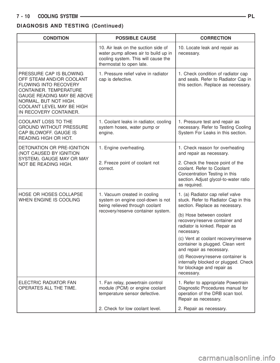
CONDITION POSSIBLE CAUSE CORRECTION
10. Air leak on the suction side of
water pump allows air to build up in
cooling system. This will cause the
thermostat to open late.10. Locate leak and repair as
necessary.
PRESSURE CAP IS BLOWING
OFF STEAM AND/OR COOLANT
FLOWING INTO RECOVERY
CONTAINER. TEMPERATURE
GAUGE READING MAY BE ABOVE
NORMAL, BUT NOT HIGH.
COOLANT LEVEL MAY BE HIGH
IN RECOVERY CONTAINER.1. Pressure relief valve in radiator
cap is defective.1. Check condition of radiator cap
and seals. Refer to Radiator Cap in
this section. Replace as necessary.
COOLANT LOSS TO THE
GROUND WITHOUT PRESSURE
CAP BLOWOFF. GAUGE IS
READING HIGH OR HOT.1. Coolant leaks in radiator, cooling
system hoses, water pump or
engine.1. Pressure test and repair as
necessary. Refer to Testing Cooling
System For Leaks in this section.
DETONATION OR PRE-IGNITION
(NOT CAUSED BY IGNITION
SYSTEM). GAUGE MAY OR MAY
NOT BE READING HIGH.1. Engine overheating. 1. Check reason for overheating
and repair as necessary.
2. Freeze point of coolant not
correct.2. Check the freeze point of the
coolant. Refer to Coolant
Concentration Testing in this
section. Adjust glycol-to-water ratio
as required.
HOSE OR HOSES COLLAPSE
WHEN ENGINE IS COOLING1. Vacuum created in cooling
system on engine cool-down is not
being relieved through coolant
recovery/reserve container system.1. (a) Radiator cap relief valve
stuck. Refer to Radiator Cap in this
section. Replace as necessary.
(b) Hose between coolant
recovery/reserve container and
radiator is kinked. Repair as
necessary.
(c) Vent at coolant recovery/reserve
container is plugged. Clean vent
and repair as necessary.
(d) Recovery/reserve container is
internally blocked or plugged. Check
for blockage and repair as
necessary.
ELECTRIC RADIATOR FAN
OPERATES ALL THE TIME.1. Fan relay, powertrain control
module (PCM) or engine coolant
temperature sensor defective.1. Refer to appropriate Powertrain
Diagnostic Procedures manual for
operation of the DRB scan tool.
Repair as necessary.
2. Check for low coolant level. 2. Repair as necessary.
7 - 10 COOLING SYSTEMPL
DIAGNOSIS AND TESTING (Continued)
Page 190 of 1285
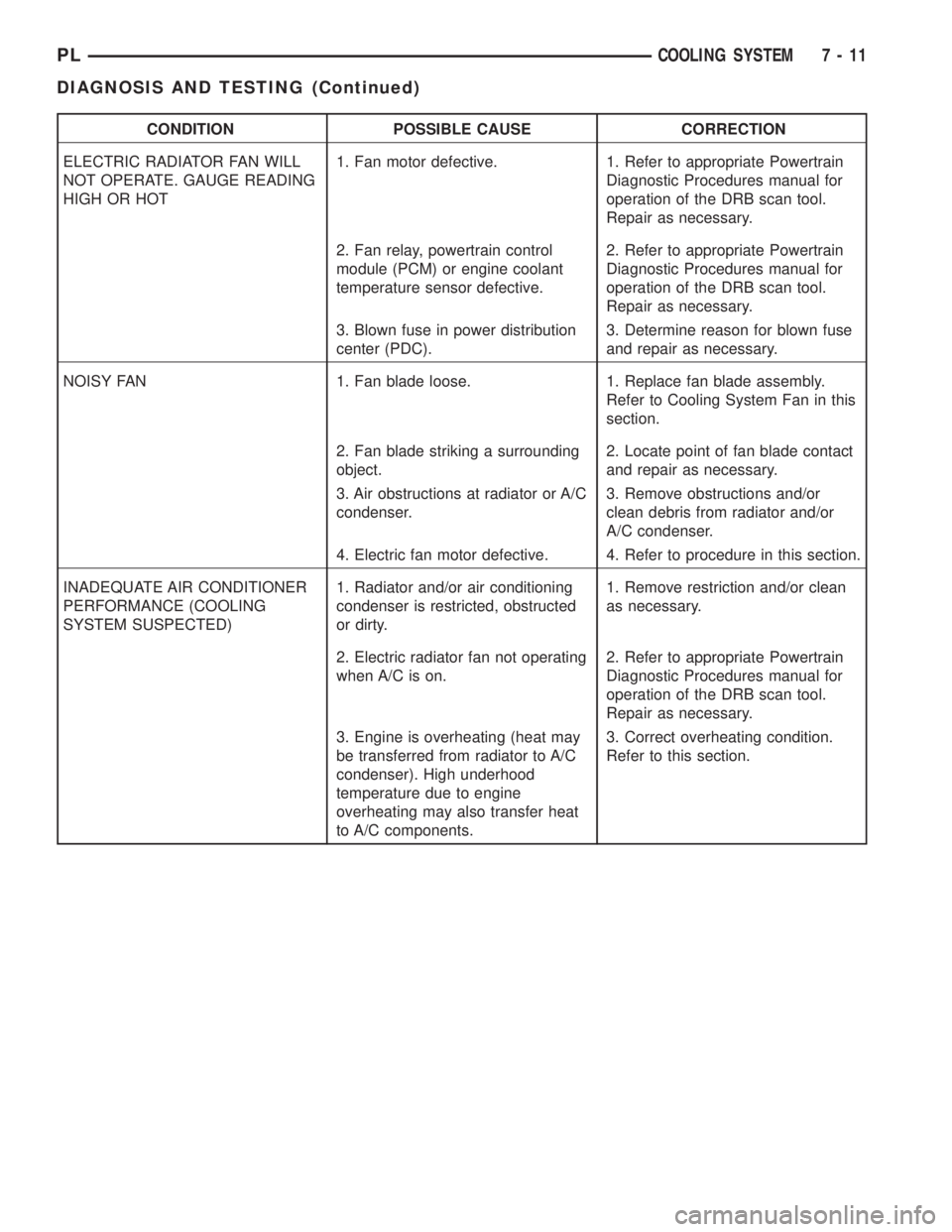
CONDITION POSSIBLE CAUSE CORRECTION
ELECTRIC RADIATOR FAN WILL
NOT OPERATE. GAUGE READING
HIGH OR HOT1. Fan motor defective. 1. Refer to appropriate Powertrain
Diagnostic Procedures manual for
operation of the DRB scan tool.
Repair as necessary.
2. Fan relay, powertrain control
module (PCM) or engine coolant
temperature sensor defective.2. Refer to appropriate Powertrain
Diagnostic Procedures manual for
operation of the DRB scan tool.
Repair as necessary.
3. Blown fuse in power distribution
center (PDC).3. Determine reason for blown fuse
and repair as necessary.
NOISY FAN 1. Fan blade loose. 1. Replace fan blade assembly.
Refer to Cooling System Fan in this
section.
2. Fan blade striking a surrounding
object.2. Locate point of fan blade contact
and repair as necessary.
3. Air obstructions at radiator or A/C
condenser.3. Remove obstructions and/or
clean debris from radiator and/or
A/C condenser.
4. Electric fan motor defective. 4. Refer to procedure in this section.
INADEQUATE AIR CONDITIONER
PERFORMANCE (COOLING
SYSTEM SUSPECTED)1. Radiator and/or air conditioning
condenser is restricted, obstructed
or dirty.1. Remove restriction and/or clean
as necessary.
2. Electric radiator fan not operating
when A/C is on.2. Refer to appropriate Powertrain
Diagnostic Procedures manual for
operation of the DRB scan tool.
Repair as necessary.
3. Engine is overheating (heat may
be transferred from radiator to A/C
condenser). High underhood
temperature due to engine
overheating may also transfer heat
to A/C components.3. Correct overheating condition.
Refer to this section.
PLCOOLING SYSTEM 7 - 11
DIAGNOSIS AND TESTING (Continued)
Page 217 of 1285
²It passes the 15 second load test. Refer to Bat-
tery Load Test.
²The built in test indicator dot is GREEN (Fig.
2).
NOTE: The battery cannot be refilled with water, it
must be replaced.
WARNING: DO NOT CHARGE A BATTERY THAT
HAS EXCESSIVELY LOW ELECTROLYTE LEVEL.
BATTERY MAY SPARK INTERNALLY AND
EXPLODE. EXPLOSIVE GASES FORM OVER THE
BATTERY. DO NOT SMOKE, USE FLAME, OR CRE-
ATE SPARKS NEAR BATTERY. DO NOT ASSIST
BOOST OR CHARGE A FROZEN BATTERY. BAT-
TERY CASING MAY FRACTURE. BATTERY ACID IS
POISON, AND MAY CAUSE SEVERE BURNS. BAT-
TERIES CONTAIN SULFURIC ACID. AVOID CON-
TACT WITH SKIN, EYES, OR CLOTHING. IN THE
EVENT OF CONTACT, FLUSH WITH WATER AND
CALL PHYSICIAN IMMEDIATELY. KEEP OUT OF
REACH OF CHILDREN.
CAUTION: Disconnect the battery NEGATIVE cable
first, before charging battery to avoid damage to
electrical systems. Lift the red battery boot cover
from the positive cable clamp. Do not exceed 16.0
volts while charging battery. Refer to the instruc-
tions supplied with charging equipment
Battery electrolyte may bubble inside of battery
case while being charged properly. If the electrolyte
boils violently, or is discharged from the vent holes
while charging, immediately reduce charging rate or
turn off charger. Evaluate battery condition. Battery
damage may occur if charging is excessive.
Some battery chargers are equipped with polarity
sensing devices to protect the charger or battery from
being damaged if improperly connected. If the bat-
tery state of charge is too low for the polarity sensor
to detect, the sensor must be bypassed for charger to
operate. Refer to operating instructions provided
with battery charger being used.
CAUTION: Charge battery until test indicator
appears green. Do not overcharge.
It may be necessary to jiggle the battery or vehicle
to bring the green dot in the test indicator into view.
After the battery has been charged to 12.4 volts or
greater, perform a load test to determine cranking
capacity. Refer to Battery Load Test in this Group. If
the battery passes the load test, the battery is OK to
use. If battery will not pass the load test, it must be
replaced. Properly clean and inspect battery holddowns, tray, terminals, cables, posts, and top before
completing service.
CHARGING COMPLETELY DISCHARGED
BATTERY
The following procedure should be used to recharge
a completely discharged battery. Unless procedure is
properly followed, a good battery may be needlessly
replaced. Refer to Battery Charging Rate Table for
proper charging time.
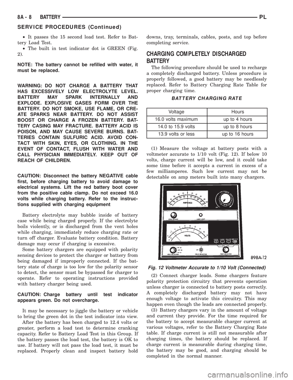
(1) Measure the voltage at battery posts with a
voltmeter accurate to 1/10 volt (Fig. 12). If below 10
volts, charge current will be low, and it could take
some time before it accepts a current in excess of a
few milliamperes. Such low current may not be
detectable on amp meters built into many chargers.
(2) Connect charger leads. Some chargers feature
polarity protection circuitry that prevents operation
unless charger is connected to battery posts correctly.
A completely discharged battery may not have
enough voltage to activate this circuitry. This may
happen even though the leads are connected properly.
(3) Battery chargers vary in the amount of voltage
and current they provide. For the time required for
the battery to accept measurable charger current at
various voltages, refer to the Battery Charging Rate
table. If charge current is still not measurable after
charging times, the battery should be replaced. If
charge current is measurable during charging time,
the battery may be good, and charging should be
completed in the normal manner.
BATTERY CHARGING RATE
Voltage Hours
16.0 volts maximum up to 4 hours
14.0 to 15.9 volts up to 8 hours
13.9 volts or less up to 16 hours
Fig. 12 Voltmeter Accurate to 1/10 Volt (Connected)
8A - 8 BATTERYPL
SERVICE PROCEDURES (Continued)
Page 232 of 1285
CHARGING SYSTEM
TABLE OF CONTENTS
page page
DESCRIPTION AND OPERATION
CHARGING SYSTEM.......................1
GENERATOR.............................1
ELECTRONIC VOLTAGE REGULATOR..........1
REMOVAL AND INSTALLATION
GENERATOR.............................2SPECIFICATIONS
GENERATOR RATINGS.....................3
TORQUE................................3
DESCRIPTION AND OPERATION
CHARGING SYSTEM
DESCRIPTION
The charging system consists of:
²Generator
²Electronic Voltage Regulator (EVR) circuitry
within the Powertrain Control Module (PCM)
²Ignition switch (refer to the Ignition System for
information)
²Battery (refer to the Battery for information)
²Battery temperature sensor
²Wiring harness and connections (refer to the
Wiring for information)
OPERATION
The charging system is turned on and off with the
ignition switch. When the ignition switch is turned to
the ON position, battery voltage is applied to the
generator rotor through one of the two field termi-
nals to produce a magnetic field. The generator is
driven by the engine through a serpentine belt and
pulley arrangement.
The amount of DC current produced by the gener-
ator is controlled by the EVR (field control) circuitry,
contained within the PCM. This circuitry is con-
nected in series with the second rotor field terminal
and ground.
Temperature data, along with data from monitored
line voltage, is used by the PCM to vary the battery
charging rate. This is done by cycling the ground
path to control the strength of the rotor magnetic
field. The PCM then compensates and regulates gen-
erator current output accordingly and to maintain
the proper voltage depending on battery tempera-
ture.
All vehicles are equipped with On-Board Diagnos-
tics (OBD). All OBD-sensed systems, including the
EVR (field control) circuitry, are monitored by thePCM. Each monitored circuit is assigned a Diagnos-
tic Trouble Code (DTC). The PCM will store a DTC in
electronic memory for any failure it detects.
GENERATOR
DESCRIPTION
The generator is belt-driven by the engine. It is
serviced only as a complete assembly. If the genera-
tor fails for any reason, the entire assembly must be
replaced.
OPERATION
As the energized rotor begins to rotate within the
generator, the spinning magnetic field induces a cur-
rent into the windings of the stator coil. Once the
generator begins producing sufficient current, it also
provides the current needed to energize the rotor.
The Y type stator winding connections deliver the
induced AC current to 3 positive and 3 negative
diodes for rectification. From the diodes, rectified DC
current is delivered to the vehicles electrical system
through the generator, battery, and ground terminals.
Noise emitting from the generator may be caused
by:
²Worn, loose or defective bearings
²Loose or defective drive pulley
²Incorrect, worn, damaged or misadjusted drive
belt
²Loose mounting bolts
²Misaligned drive pulley
²Defective stator or diode
²Damaged internal fins
ELECTRONIC VOLTAGE REGULATOR
DESCRIPTION
The Electronic Voltage Regulator (EVR) is not a
separate component. It is actually a voltage regulat-
ing circuit located within the Powertrain Control
PLCHARGING SYSTEM 8C - 1
Page 233 of 1285
Module (PCM). The EVR is not serviced separately. If
replacement is necessary, the PCM must be replaced.
OPERATION
The amount of DC current produced by the gener-
ator is controlled by EVR circuitry contained within
the PCM. This circuitry is connected in series with
the generators second rotor field terminal and its
ground.
Voltage is regulated by cycling the ground path to
control the strength of the rotor magnetic field. The
EVR circuitry monitors system line voltage (B+) and
battery temperature (refer to Battery Temperature
Sensor for more information). It then determines a
target charging voltage. If sensed battery voltage is
0.5 volts or lower than the target voltage, the PCM
grounds the field winding until sensed battery volage
is 0.5 volts above target voltage. A circuit in the PCM
cycles the ground side of the generator field up to
100 times per second (100Hz), but has the capability
to ground the field control wire 100% of the time (full
field) to achieve the target voltage. If the charging
rate cannot be monitored (limp-in), a duty cycle of
25% is used by the PCM in order to have some gen-
erator output. Also refer to Charging System Opera-
tion for additional information.
REMOVAL AND INSTALLATION
GENERATOR
REMOVAL
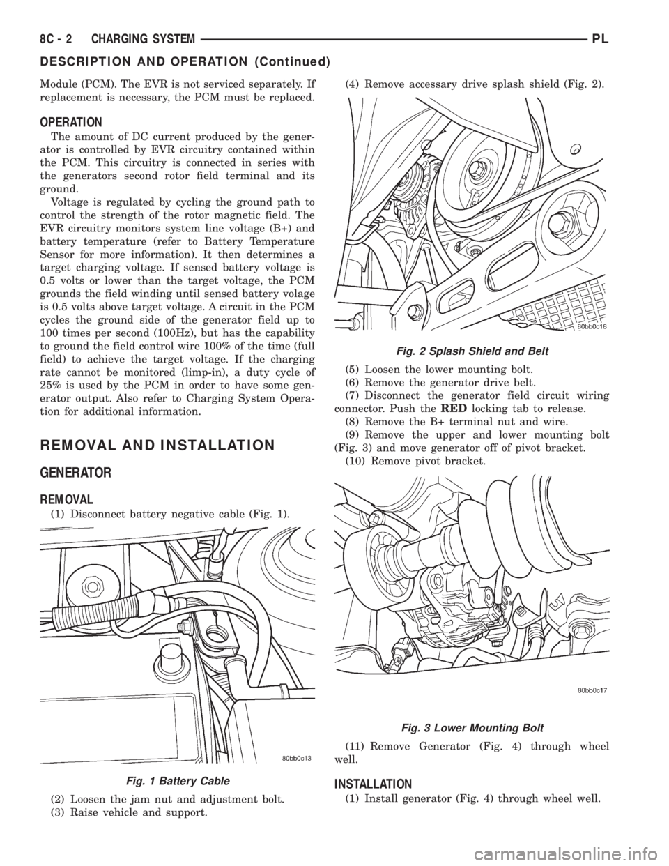
(1) Disconnect battery negative cable (Fig. 1).
(2) Loosen the jam nut and adjustment bolt.
(3) Raise vehicle and support.(4) Remove accessary drive splash shield (Fig. 2).
(5) Loosen the lower mounting bolt.
(6) Remove the generator drive belt.
(7) Disconnect the generator field circuit wiring
connector. Push theREDlocking tab to release.
(8) Remove the B+ terminal nut and wire.
(9) Remove the upper and lower mounting bolt
(Fig. 3) and move generator off of pivot bracket.
(10) Remove pivot bracket.
(11) Remove Generator (Fig. 4) through wheel
well.
INSTALLATION
(1) Install generator (Fig. 4) through wheel well.
Fig. 1 Battery Cable
Fig. 2 Splash Shield and Belt
Fig. 3 Lower Mounting Bolt
8C - 2 CHARGING SYSTEMPL
DESCRIPTION AND OPERATION (Continued)
Page 236 of 1285
IGNITION SYSTEM
TABLE OF CONTENTS
page page
DESCRIPTION AND OPERATION
IGNITION SYSTEM........................1
SPARK PLUGS...........................1
SPARK PLUG CABLES.....................1
ELECTRONIC IGNITION COILS...............2
AUTOMATIC SHUTDOWN RELAY.............2
CRANKSHAFT POSITION SENSORÐPCM
INPUT................................3
CAMSHAFT POSITION SENSORÐPCM
INPUT................................4
KNOCK SENSOR..........................5
IGNITION SWITCH........................5
LOCK KEY CYLINDER......................5
IGNITION INTERLOCK.....................6
REMOVAL AND INSTALLATION
SPARK PLUG SERVICE....................6SPARK PLUG CABLE SERVICE..............6
IGNITION COIL...........................6
AUTOMATIC SHUTDOWN RELAY.............6
CAMSHAFT POSITION SENSOR..............6
CRANKSHAFT POSITION SENSOR............8
KNOCK SENSOR..........................8
IGNITION SWITCH........................8
LOCK KEY CYLINDER......................9
IGNITION INTERLOCK....................10
SPECIFICATIONS
VECI LABEL............................10
FIRING ORDERÐ2.0L....................10
TORQUE SPECIFICATION..................11
SPARK PLUG CABLE RESISTANCEÐSOHC....11
SPARK PLUG...........................11
IGNITION COIL..........................11
DESCRIPTION AND OPERATION
IGNITION SYSTEM
DESCRIPTION
The system's three main components are the coil
pack, crankshaft position sensor, and camshaft posi-
tion sensor.
OPERATION
Basic ignition timing is not adjustable.The
Powertrain Control Module (PCM) determines spark
advance. The 2.0L engines use a fixed ignition timing
system. The distributorless electronic ignition system
is referred to as the Direct Ignition System (DIS).
SPARK PLUGS
The 2.0L engines uses resistor spark plugs. For
spark plug identification and specifications, Refer to
the Specifications section at the end of this group.
Remove the spark plugs and examine them for
burned electrodes and fouled, cracked or broken por-
celain insulators. Keep plugs arranged in the order
in which they were removed from the engine. An iso-
lated plug displaying an abnormal condition indicates
that a problem exists in the corresponding cylinder.
Spark plugs that have low mileage may be cleaned
and reused if not otherwise defective. Refer to the
Spark Plug Condition section of this group. Aftercleaning, file the center electrode flat with a small
point file or jewelers file. Adjust the gap between the
electrodes (Fig. 1) to the dimensions specified in the
chart at the end of this section by bending the
ground electrode (just above the attachment weld)
with the appropriate tool.
Never apply any force between the electrode or
damage to the center electrode assembly will result.
Always tighten spark plugs to the specified torque.
Over tightening can cause distortion and damage.
Tighten spark plugs to 28 N´m (20 ft. lbs.) torque.
SPARK PLUG CABLES
Spark plug cables are sometimes referred to as sec-
ondary ignition wires. The wires transfer electrical
current from the coil pack to individual spark plugs
at each cylinder. The resistor type, nonmetallic spark
plug cables provide suppression of radio frequency
emissions from the ignition system.
Check the spark plug cable connections for good
contact at the coil and spark plugs. Terminals should
be fully seated. The nipples and spark plug covers
should be in good condition. Nipples should fit tightly
on the coil. Spark plug boot should completely cover
the spark plug hole in the cylinder head cover. Install
the boot until the terminal snaps over the spark
plug. A snap must be felt to ensure the spark plug
cable terminal engaged the spark plug.
PLIGNITION SYSTEM 8D - 1
Page 237 of 1285

Loose cable connections will corrode, increase resis-
tance and permit water to enter the coil towers.
These conditions can cause ignition malfunction.
Plastic clips in various locations protect the cables
from damage. When the cables are replaced the clips
must be used to prevent damage to the cables, and
should be rotated about 30É below the horizontal.
ELECTRONIC IGNITION COILS
DESCRIPTION
The coil pack consists of 2 coils molded together.
The coil pack is mounted on the valve cover (Fig. 2).
OPERATION
WARNING: THE DIRECT IGNITION SYSTEM GEN-
ERATES APPROXIMATELY 40,000 VOLTS. PER-
SONAL INJURY COULD RESULT FROM CONTACT
WITH THIS SYSTEM.
High tension leads route to each cylinder from the
coil. The coil fires two spark plugs every power
stroke. One plug is the cylinder under compression,
the other cylinder fires on the exhaust stroke. Coil
number one fires cylinders 1 and 4. Coil number two
fires cylinders 2 and 3. The PCM determines which
of the coils to charge and fire at the correct time.
The Auto Shutdown (ASD) relay provides battery
voltage to the ignition coil. The PCM provides a
ground contact (circuit) for energizing the coil. When
the PCM breaks the contact, the energy in the coil
primary transfers to the secondary causing thespark. The PCM will de-energize the ASD relay if it
does not receive the crankshaft position sensor and
camshaft position sensor inputs. Refer to Auto Shut-
down (ASD) RelayÐPCM Output, in this section for
relay operation.
AUTOMATIC SHUTDOWN RELAY
DESCRIPTION
The ASD relay is located in the PDC (Fig. 3). The
inside top of the PDC cover has label showing relay
and fuse identification.
Fig. 1 Checking Spark Plug Electrode Gap
1 ± TAPER GAUGE
Fig. 2 Ignition Coil Pack
1 ± IGNITION COILS
2 ± SPARK PLUG CABLE
3 ± SPARK PLUG INSULATOR
Fig. 3 Power Distribution Center (PDC)
8D - 2 IGNITION SYSTEMPL
DESCRIPTION AND OPERATION (Continued)
Page 238 of 1285
OPERATION
The Automatic Shutdown (ASD) relay supplies bat-
tery voltage to the fuel injectors, electronic ignition
coil and the heating elements in the oxygen sensors.
A buss bar in the Power Distribution Center (PDC)
supplies voltage to the solenoid side and contact side
of the relay. The fuse also protects the power circuit
for the fuel pump relay and pump. The fuse is
located in the PDC. Refer to the Wiring Diagrams for
circuit information.
The PCM controls the ASD relay by switching the
ground path for the solenoid side of the relay on and
off. The PCM turns the ground path off when the
ignition switch is in the Off position. When the igni-
tion switch is in On or Start, the PCM monitors the
crankshaft and camshaft position sensor signals to
determine engine speed and ignition timing (coil
dwell). If the PCM does not receive crankshaft and
camshaft position sensor signals when the ignition
switch is in the Run position, it will de-energize the
ASD relay.
CRANKSHAFT POSITION SENSORÐPCM
INPUT
DESCRIPTION
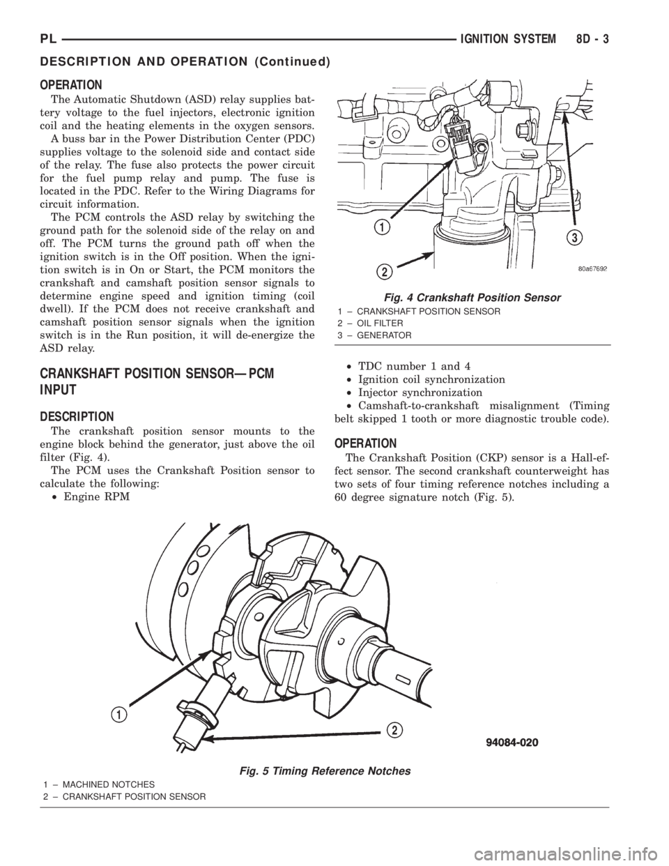
The crankshaft position sensor mounts to the
engine block behind the generator, just above the oil
filter (Fig. 4).
The PCM uses the Crankshaft Position sensor to
calculate the following:
²Engine RPM²TDC number 1 and 4
²Ignition coil synchronization
²Injector synchronization
²Camshaft-to-crankshaft misalignment (Timing
belt skipped 1 tooth or more diagnostic trouble code).
OPERATION
The Crankshaft Position (CKP) sensor is a Hall-ef-
fect sensor. The second crankshaft counterweight has
two sets of four timing reference notches including a
60 degree signature notch (Fig. 5).
Fig. 5 Timing Reference Notches
1 ± MACHINED NOTCHES
2 ± CRANKSHAFT POSITION SENSOR
Fig. 4 Crankshaft Position Sensor
1 ± CRANKSHAFT POSITION SENSOR
2 ± OIL FILTER
3 ± GENERATOR
PLIGNITION SYSTEM 8D - 3
DESCRIPTION AND OPERATION (Continued)