2000 DODGE NEON airbag
[x] Cancel search: airbagPage 643 of 1285

P36 18PK/VT DOOR UNLOCK DRIVER
P33 18OR/BK DOOR LOCK DRIVER
4 2 GRAY
OXYGEN SENSOR 1/1 SIGNAL 20BK/DG K41 4OXYGEN SENSOR GROUND K127 18BK/OR 3
HEATED OXYGEN SENSOR RELAY CONTROL K79 18OR/RD 2
AUTOMATIC SHUT DOWN RELAY OUTPUT 18DG/OR A142 1
FUNCTION CIRCUIT CAV
CAV CIRCUIT FUNCTION
1
A142 18DG/ORAUTOMATIC SHUT DOWN RELAY OUTPUT
2Z1 18BKGROUND
3K127 18BK/OROXYGEN SENSOR GROUND
4K141 20TN/WT
OXYGEN SENSOR 1/2 SIGNAL
2
41
3
1/2 DOWNSTREAMOXYGEN SENSOR
(2.0L)
FUSED IGNITION SWITCH OUTPUT (RUN) 18WT F20 3PARK/NEUTRAL POSITION SWITCH SENSE 18BR/YL T41 2BACK-UP LAMP FEED 18VT/BK L1 1FUNCTION CIRCUIT CAV
POSITION SWITCHPARK/NEUTRAL
BLACK
3 1
PASSENGER
DOOR LOCK
MOTOR OXYGEN SENSOR
1/1 UPSTREAM
BLACK
34
2 1
4
3
2
-
- 1
FUNCTION CIRCUIT CAV
--
LOCK SWITCH PASSENGER CYLINDER
GROUND Z14 18BK 2PASSENGER DOOR SWITCH MUX P96 18LG 1
FUNCTION CIRCUIT CAV
GRAY 3 1
AIRBAG PASSENGER
YELLOW
1 4
PASSENGER AIRBAG LINE 2 18BK/YL R42 4PASSENGER AIRBAG LINE 1 18DG/YL R44 3
- - 2
- - 1
FUNCTION CIRCUIT CAV
BLACK
(ATX)
8W - 80 - 34 8W-80 CONNECTOR PIN-OUTSPL
008W-10PLI08034
Page 658 of 1285
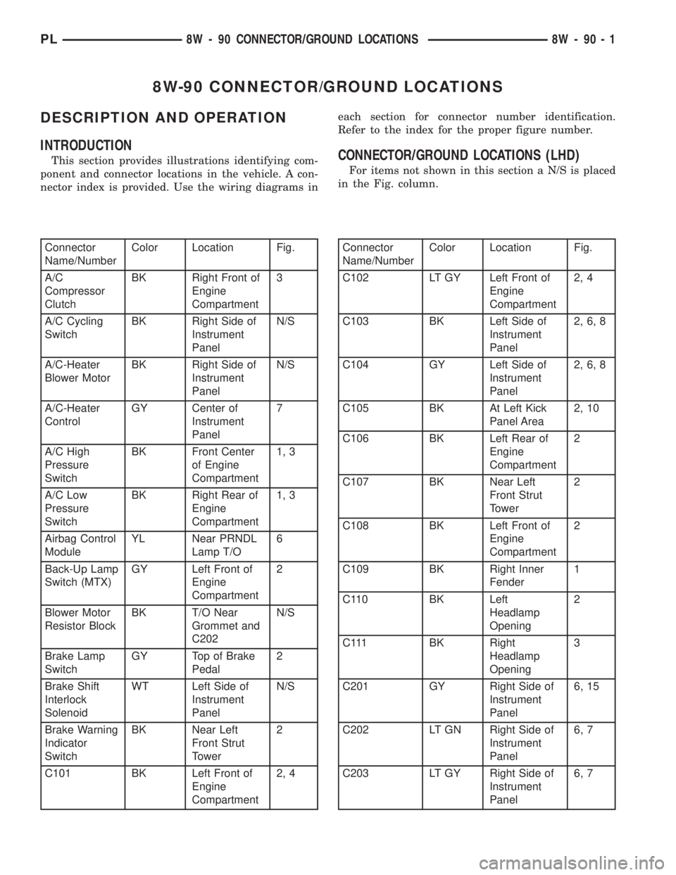
8W-90 CONNECTOR/GROUND LOCATIONS
DESCRIPTION AND OPERATION
INTRODUCTION
This section provides illustrations identifying com-
ponent and connector locations in the vehicle. A con-
nector index is provided. Use the wiring diagrams ineach section for connector number identification.
Refer to the index for the proper figure number.CONNECTOR/GROUND LOCATIONS (LHD)
For items not shown in this section a N/S is placed
in the Fig. column.
Connector
Name/NumberColor Location Fig.
A/C
Compressor
ClutchBK Right Front of
Engine
Compartment3
A/C Cycling
SwitchBK Right Side of
Instrument
PanelN/S
A/C-Heater
Blower MotorBK Right Side of
Instrument
PanelN/S
A/C-Heater
ControlGY Center of
Instrument
Panel7
A/C High
Pressure
SwitchBK Front Center
of Engine
Compartment1, 3
A/C Low
Pressure
SwitchBK Right Rear of
Engine
Compartment1, 3
Airbag Control
ModuleYL Near PRNDL
Lamp T/O6
Back-Up Lamp
Switch (MTX)GY Left Front of
Engine
Compartment2
Blower Motor
Resistor BlockBK T/O Near
Grommet and
C202N/S
Brake Lamp
SwitchGY Top of Brake
Pedal2
Brake Shift
Interlock
SolenoidWT Left Side of
Instrument
PanelN/S
Brake Warning
Indicator
SwitchBK Near Left
Front Strut
Tower2
C101 BK Left Front of
Engine
Compartment2, 4Connector
Name/NumberColor Location Fig.
C102 LT GY Left Front of
Engine
Compartment2, 4
C103 BK Left Side of
Instrument
Panel2, 6, 8
C104 GY Left Side of
Instrument
Panel2, 6, 8
C105 BK At Left Kick
Panel Area2, 10
C106 BK Left Rear of
Engine
Compartment2
C107 BK Near Left
Front Strut
Tower2
C108 BK Left Front of
Engine
Compartment2
C109 BK Right Inner
Fender1
C110 BK Left
Headlamp
Opening2
C111 BK Right
Headlamp
Opening3
C201 GY Right Side of
Instrument
Panel6, 15
C202 LT GN Right Side of
Instrument
Panel6, 7
C203 LT GY Right Side of
Instrument
Panel6, 7
PL8W - 90 CONNECTOR/GROUND LOCATIONS 8W - 90 - 1
Page 661 of 1285
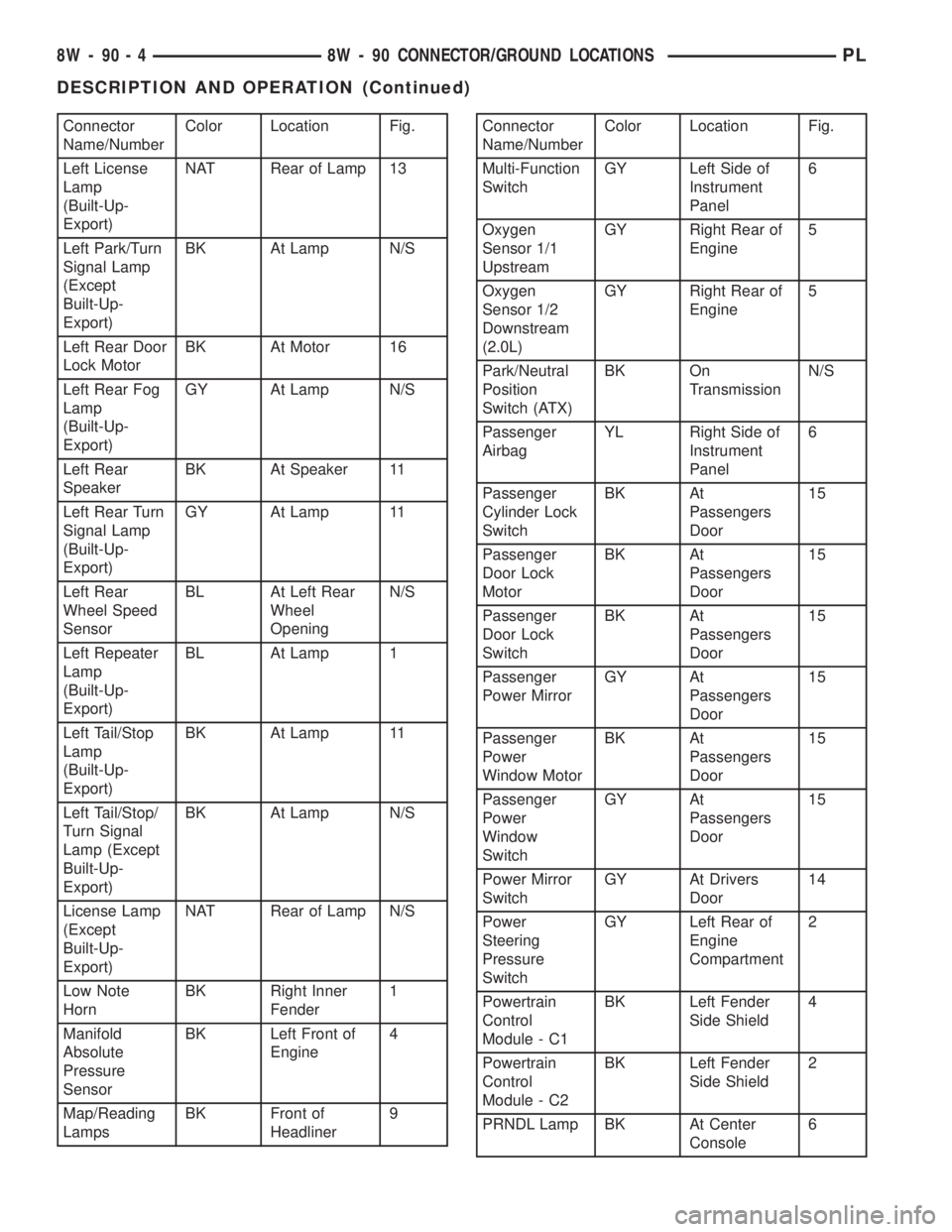
Connector
Name/NumberColor Location Fig.
Left License
Lamp
(Built-Up-
Export)NAT Rear of Lamp 13
Left Park/Turn
Signal Lamp
(Except
Built-Up-
Export)BK At Lamp N/S
Left Rear Door
Lock MotorBK At Motor 16
Left Rear Fog
Lamp
(Built-Up-
Export)GY At Lamp N/S
Left Rear
SpeakerBK At Speaker 11
Left Rear Turn
Signal Lamp
(Built-Up-
Export)GY At Lamp 11
Left Rear
Wheel Speed
SensorBL At Left Rear
Wheel
OpeningN/S
Left Repeater
Lamp
(Built-Up-
Export)BL At Lamp 1
Left Tail/Stop
Lamp
(Built-Up-
Export)BK At Lamp 11
Left Tail/Stop/
Turn Signal
Lamp (Except
Built-Up-
Export)BK At Lamp N/S
License Lamp
(Except
Built-Up-
Export)NAT Rear of Lamp N/S
Low Note
HornBK Right Inner
Fender1
Manifold
Absolute
Pressure
SensorBK Left Front of
Engine4
Map/Reading
LampsBK Front of
Headliner9Connector
Name/NumberColor Location Fig.
Multi-Function
SwitchGY Left Side of
Instrument
Panel6
Oxygen
Sensor 1/1
UpstreamGY Right Rear of
Engine5
Oxygen
Sensor 1/2
Downstream
(2.0L)GY Right Rear of
Engine5
Park/Neutral
Position
Switch (ATX)BK On
TransmissionN/S
Passenger
AirbagYL Right Side of
Instrument
Panel6
Passenger
Cylinder Lock
SwitchBK At
Passengers
Door15
Passenger
Door Lock
MotorBK At
Passengers
Door15
Passenger
Door Lock
SwitchBK At
Passengers
Door15
Passenger
Power MirrorGY At
Passengers
Door15
Passenger
Power
Window MotorBK At
Passengers
Door15
Passenger
Power
Window
SwitchGY At
Passengers
Door15
Power Mirror
SwitchGY At Drivers
Door14
Power
Steering
Pressure
SwitchGY Left Rear of
Engine
Compartment2
Powertrain
Control
Module - C1BK Left Fender
Side Shield4
Powertrain
Control
Module - C2BK Left Fender
Side Shield2
PRNDL Lamp BK At Center
Console6
8W - 90 - 4 8W - 90 CONNECTOR/GROUND LOCATIONSPL
DESCRIPTION AND OPERATION (Continued)
Page 678 of 1285
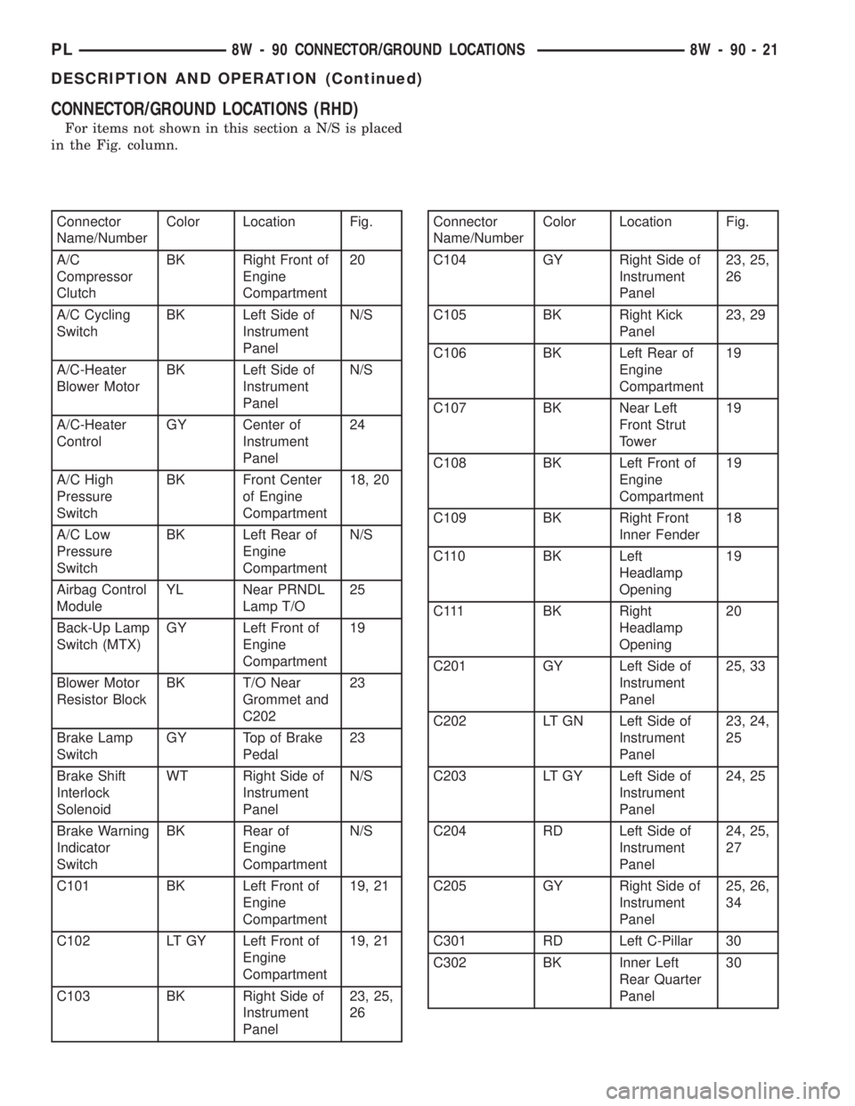
CONNECTOR/GROUND LOCATIONS (RHD)
For items not shown in this section a N/S is placed
in the Fig. column.
Connector
Name/NumberColor Location Fig.
A/C
Compressor
ClutchBK Right Front of
Engine
Compartment20
A/C Cycling
SwitchBK Left Side of
Instrument
PanelN/S
A/C-Heater
Blower MotorBK Left Side of
Instrument
PanelN/S
A/C-Heater
ControlGY Center of
Instrument
Panel24
A/C High
Pressure
SwitchBK Front Center
of Engine
Compartment18, 20
A/C Low
Pressure
SwitchBK Left Rear of
Engine
CompartmentN/S
Airbag Control
ModuleYL Near PRNDL
Lamp T/O25
Back-Up Lamp
Switch (MTX)GY Left Front of
Engine
Compartment19
Blower Motor
Resistor BlockBK T/O Near
Grommet and
C20223
Brake Lamp
SwitchGY Top of Brake
Pedal23
Brake Shift
Interlock
SolenoidWT Right Side of
Instrument
PanelN/S
Brake Warning
Indicator
SwitchBK Rear of
Engine
CompartmentN/S
C101 BK Left Front of
Engine
Compartment19, 21
C102 LT GY Left Front of
Engine
Compartment19, 21
C103 BK Right Side of
Instrument
Panel23, 25,
26Connector
Name/NumberColor Location Fig.
C104 GY Right Side of
Instrument
Panel23, 25,
26
C105 BK Right Kick
Panel23, 29
C106 BK Left Rear of
Engine
Compartment19
C107 BK Near Left
Front Strut
Tower19
C108 BK Left Front of
Engine
Compartment19
C109 BK Right Front
Inner Fender18
C110 BK Left
Headlamp
Opening19
C111 BK Right
Headlamp
Opening20
C201 GY Left Side of
Instrument
Panel25, 33
C202 LT GN Left Side of
Instrument
Panel23, 24,
25
C203 LT GY Left Side of
Instrument
Panel24, 25
C204 RD Left Side of
Instrument
Panel24, 25,
27
C205 GY Right Side of
Instrument
Panel25, 26,
34
C301 RD Left C-Pillar 30
C302 BK Inner Left
Rear Quarter
Panel30
PL8W - 90 CONNECTOR/GROUND LOCATIONS 8W - 90 - 21
DESCRIPTION AND OPERATION (Continued)
Page 681 of 1285
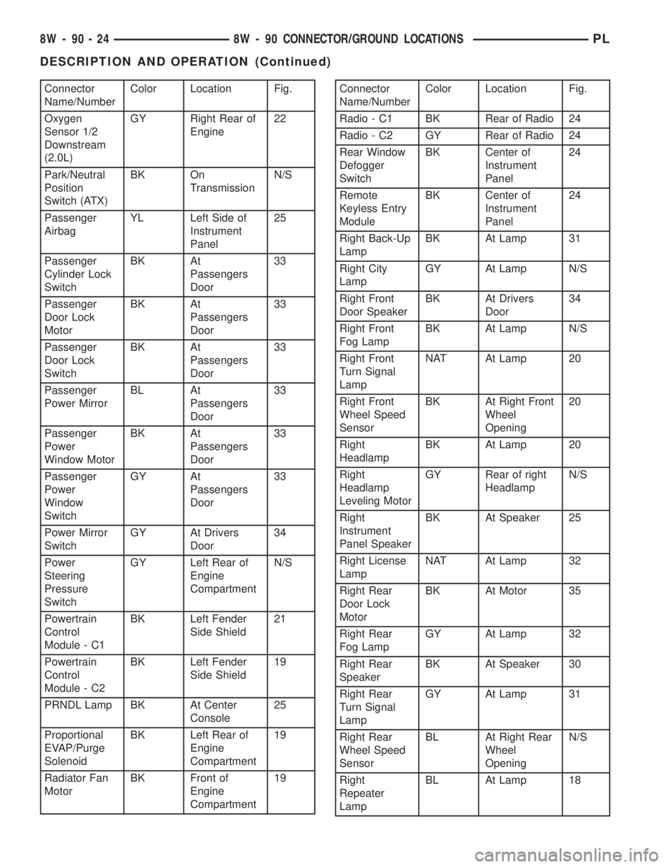
Connector
Name/NumberColor Location Fig.
Oxygen
Sensor 1/2
Downstream
(2.0L)GY Right Rear of
Engine22
Park/Neutral
Position
Switch (ATX)BK On
TransmissionN/S
Passenger
AirbagYL Left Side of
Instrument
Panel25
Passenger
Cylinder Lock
SwitchBK At
Passengers
Door33
Passenger
Door Lock
MotorBK At
Passengers
Door33
Passenger
Door Lock
SwitchBK At
Passengers
Door33
Passenger
Power MirrorBL At
Passengers
Door33
Passenger
Power
Window MotorBK At
Passengers
Door33
Passenger
Power
Window
SwitchGY At
Passengers
Door33
Power Mirror
SwitchGY At Drivers
Door34
Power
Steering
Pressure
SwitchGY Left Rear of
Engine
CompartmentN/S
Powertrain
Control
Module - C1BK Left Fender
Side Shield21
Powertrain
Control
Module - C2BK Left Fender
Side Shield19
PRNDL Lamp BK At Center
Console25
Proportional
EVAP/Purge
SolenoidBK Left Rear of
Engine
Compartment19
Radiator Fan
MotorBK Front of
Engine
Compartment19Connector
Name/NumberColor Location Fig.
Radio - C1 BK Rear of Radio 24
Radio - C2 GY Rear of Radio 24
Rear Window
Defogger
SwitchBK Center of
Instrument
Panel24
Remote
Keyless Entry
ModuleBK Center of
Instrument
Panel24
Right Back-Up
LampBK At Lamp 31
Right City
LampGY At Lamp N/S
Right Front
Door SpeakerBK At Drivers
Door34
Right Front
Fog LampBK At Lamp N/S
Right Front
Turn Signal
LampNAT At Lamp 20
Right Front
Wheel Speed
SensorBK At Right Front
Wheel
Opening20
Right
HeadlampBK At Lamp 20
Right
Headlamp
Leveling MotorGY Rear of right
HeadlampN/S
Right
Instrument
Panel SpeakerBK At Speaker 25
Right License
LampNAT At Lamp 32
Right Rear
Door Lock
MotorBK At Motor 35
Right Rear
Fog LampGY At Lamp 32
Right Rear
SpeakerBK At Speaker 30
Right Rear
Turn Signal
LampGY At Lamp 31
Right Rear
Wheel Speed
SensorBL At Right Rear
Wheel
OpeningN/S
Right
Repeater
LampBL At Lamp 18
8W - 90 - 24 8W - 90 CONNECTOR/GROUND LOCATIONSPL
DESCRIPTION AND OPERATION (Continued)
Page 900 of 1285
STEERING COLUMN
TABLE OF CONTENTS
page page
DESCRIPTION AND OPERATION
STEERING COLUMN......................29
STEERING COLUMN LOWER COUPLING......29
DIAGNOSIS AND TESTING
STEERING COLUMN......................30
STEERING COLUMN LOWER COUPLING......30
REMOVAL AND INSTALLATION
SERVICE WARNINGS AND CAUTIONS........31STEERING COLUMN......................31
STEERING COLUMN LOWER COUPLING......38
SPECIFICATIONS
STEERING COLUMN FASTENER TORQUE
SPECIFICATIONS.......................41
DESCRIPTION AND OPERATION
STEERING COLUMN
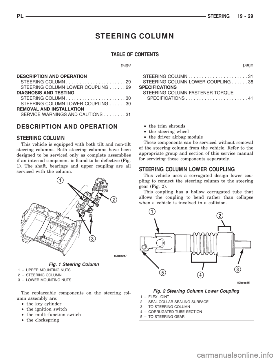
This vehicle is equipped with both tilt and non-tilt
steering columns. Both steering columns have been
designed to be serviced only as complete assemblies
if an internal component is found to be defective (Fig.
1). The shaft, bearings and upper coupling are all
serviced with the column.
The replaceable components on the steering col-
umn assembly are:
²the key cylinder
²the ignition switch
²the multi-function switch
²the clockspring²the trim shrouds
²the steering wheel
²the driver airbag module
These components can be serviced without removal
of the steering column from the vehicle. Refer to the
appropriate group and section of this service manual
for servicing these components separately.
STEERING COLUMN LOWER COUPLING
This vehicle uses a corrugated design lower cou-
pling to connect the steering column to the steering
gear (Fig. 2).
This coupling has a hollow corrugated tube that
allows the coupling to bend rather than collapse
when a vehicle is involved in a collision.
Fig. 1 Steering Column
1 ± UPPER MOUNTING NUTS
2 ± STEERING COLUMN
3 ± LOWER MOUNTING NUTS
Fig. 2 Steering Column Lower Coupling
1 ± FLEX JOINT
2 ± SEAL COLLAR SEALING SURFACE
3 ± TO STEERING COLUMN
4 ± CORRUGATED TUBE SECTION
5 ± TO STEERING GEAR
PLSTEERING 19 - 29
Page 903 of 1285
REMOVAL
(1) Disconnect the negative (-) cable from the bat-
tery and isolate the cable.
(2) Before beginning removal of the steering col-
umn, be sure the front wheels of vehicle are in the
STRAIGHT-AHEAD position.
(3) Remove the screw securing the left end of the
top cover to the instrument panel. It is located just
above the left instrument panel end cap.
(4) Starting on the driver's end, push upward on
the instrument panel top cover, disengaging its
retainer clips along the face of the instrument panel.
Disengage just enough clips to allow access to the
upper ends of the instrument cluster bezel.
(5) Disengage the clips along the outer edge of the
instrument cluster bezel and remove the bezel from
the vehicle.
(6) Remove the two screws along the bottom of the
steering column cover that mounts below the steering
column on the instrument panel. Disengage the clips
on the upper end of the steering column cover and
remove the cover by pulling it straight away from the
instrument panel.
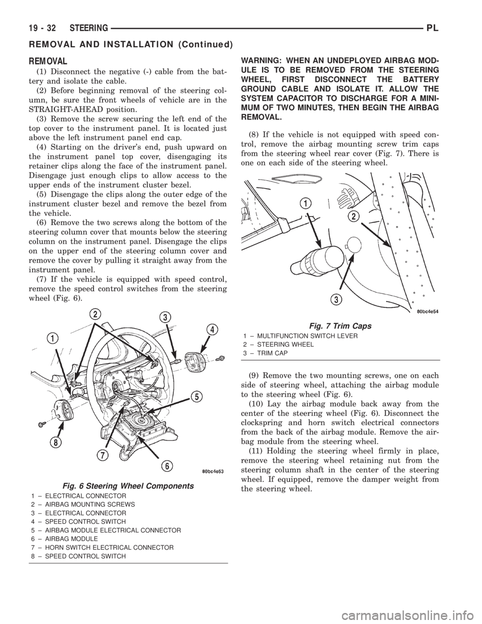
(7) If the vehicle is equipped with speed control,
remove the speed control switches from the steering
wheel (Fig. 6).WARNING: WHEN AN UNDEPLOYED AIRBAG MOD-
ULE IS TO BE REMOVED FROM THE STEERING
WHEEL, FIRST DISCONNECT THE BATTERY
GROUND CABLE AND ISOLATE IT. ALLOW THE
SYSTEM CAPACITOR TO DISCHARGE FOR A MINI-
MUM OF TWO MINUTES, THEN BEGIN THE AIRBAG
REMOVAL.
(8) If the vehicle is not equipped with speed con-
trol, remove the airbag mounting screw trim caps
from the steering wheel rear cover (Fig. 7). There is
one on each side of the steering wheel.
(9) Remove the two mounting screws, one on each
side of steering wheel, attaching the airbag module
to the steering wheel (Fig. 6).
(10) Lay the airbag module back away from the
center of the steering wheel (Fig. 6). Disconnect the
clockspring and horn switch electrical connectors
from the back of the airbag module. Remove the air-
bag module from the steering wheel.
(11) Holding the steering wheel firmly in place,
remove the steering wheel retaining nut from the
steering column shaft in the center of the steering
wheel. If equipped, remove the damper weight from
the steering wheel.
Fig. 6 Steering Wheel Components
1 ± ELECTRICAL CONNECTOR
2 ± AIRBAG MOUNTING SCREWS
3 ± ELECTRICAL CONNECTOR
4 ± SPEED CONTROL SWITCH
5 ± AIRBAG MODULE ELECTRICAL CONNECTOR
6 ± AIRBAG MODULE
7 ± HORN SWITCH ELECTRICAL CONNECTOR
8 ± SPEED CONTROL SWITCH
Fig. 7 Trim Caps
1 ± MULTIFUNCTION SWITCH LEVER
2 ± STEERING WHEEL
3 ± TRIM CAP
19 - 32 STEERINGPL
REMOVAL AND INSTALLATION (Continued)
Page 908 of 1285
bolt nut to a torque of 28 N´m (250 in. lbs.). Install
the pinch bolt retainer pin.
(11) Install the upper and lower steering column
shrouds onto the steering column (Fig. 9). Snap the
two shrouds together and then install and tighten
the two screws securing the shrouds to the column.
(12) Install the steering column cover that mounts
below the steering column on the instrument panel
by first aligning the retainer clips and snapping the
cover into place. Install the two screws along the bot-
tom of the steering column cover.
(13) Align the clips along the outer edge of the
instrument cluster bezel with the mounting holes in
the instrument panel and install the bezel.
(14) Align the clips on the bottom of the instru-
ment panel top cover with the mounting holes in the
instrument panel and install the top cover by push-
ing it down into place.
(15) Install the screw securing the left end of the
top cover to the instrument panel.
CAUTION: If there is any question as to whether
the clockspring is in the centered position, the
clock spring needs to be recentered before install-
ing the steering wheel. If the clockspring is not cen-
tered, it may be overextended, causing the
clockspring to become inoperative.
(16) Center the clockspring using the following
procedure:
²Using your fingers, rotate the clockspring rotor
in the CLOCKWISE DIRECTION to the end of the
travel. Do not apply excessive torque.
²From the end of travel, rotate the rotor two full
turns and an additional half turn in the counter-
clockwise direction. (The wires should end up at the
bottom of the clockspring).
CAUTION: Do not install the steering wheel onto
the shaft of the steering column by driving it onto
the shaft.
(17) Feed the clockspring wiring leads through the
hole in the steering wheel (Fig. 6). Align the steering
wheel's wide mounting spline with the steering col-
umn shaft missing spline area and push the wheel
onto the shaft. Make sure the clockspring squares up
with the back of the wheel and does not bind.
(18) Install the steering wheel retaining nut and
tighten it until the steering wheel is fully installed
on shaft. Tighten the steering wheel retaining nut to
a torque of 61 N´m (45 ft. lbs.).
(19) Connect the clockspring electrical leads to the
speed control switches and reinstall the switches on
the steering wheel (Fig. 6).
(20) Install the airbag electrical lead from the
clockspring into the connector on the back of the air-bag module (Fig. 6). Be sure electrical connector from
clockspring is securely latched into airbag module
connector.
(21) Connect the horn switch electrical lead to the
connector on the back of the airbag module (Fig. 6).
CAUTION: The fasteners originally used for the air-
bag components are specifically designed for the
airbag system. They must never be replaced with
any substitutes. Anytime a new fastener is needed,
replace it with only the correct fastener listed in the
parts book.
(22) Install the airbag module into the center of
the steering wheel. Align the airbag module mount-
ing holes with the bolt holes in steering wheel (Fig.
6). Install only the two original or identical replace-
ment airbag module mounting screws. Tighten the
two air bag module attaching bolts to a torque of 10
N´m (90 in. lbs.).
(23) Install the airbag mounting screw trim caps
on the steering wheel rear cover (Fig. 7). One belongs
on each side of the steering wheel.
NOTE: When reconnecting the battery on a vehicle
that has had the airbag module removed, the fol-
lowing procedure should be used.
(24) Reconnect the ground cable to the negative
post of the battery in the following manor:
²Connect a scan tool (DRBIIIt) to the data link
diagnostic connector located below the steering col-
umn.
²Turn the ignition key to the ON position. Exit
the vehicle with the scan tool leaving the scan tool
harness plugged in.
²Ensuring that there are no occupants in the
vehicle, connect the ground (-) cable to the negative
post of the battery.
²Using the scan tool, read and record any fault
codes. Refer to the DRIVER AND PASSENGER AIR-
BAG SYSTEM diagnostic manual if any faults are
found.
²Erase any stored faults if there are no active
fault codes. If a problem exists, the fault code will
not erase.
²Reach around the back of the steering wheel (in
front of the instrument cluster) and turn the ignition
key to OFF, then back ON while observing the
instrument cluster airbag lamp. It should go on for
six to eight seconds, then go out. This will indicate
that the airbag system is functioning normally. If air-
bag warning lamp fails to light, blinks on and off, or
goes on and stays on, there is an airbag system mal-
function. Refer to the BODY DIAGNOSTIC PROCE-
DURES manual to diagnose the system malfunction.
PLSTEERING 19 - 37
REMOVAL AND INSTALLATION (Continued)