2000 DODGE NEON airbag
[x] Cancel search: airbagPage 280 of 1285
HORNS
TABLE OF CONTENTS
page page
DESCRIPTION AND OPERATION
INTRODUCTION..........................1
DIAGNOSIS AND TESTING
HORN..................................2
HORN RELAY............................2
HORN SWITCH...........................2HORN SYSTEM TEST......................2
REMOVAL AND INSTALLATION
HORN..................................4
HORN RELAY............................4
HORN SWITCH...........................5
DESCRIPTION AND OPERATION
INTRODUCTION
WARNING: ON VEHICLES EQUIPPED WITH AIR-
BAG, SEE GROUP 8M, PASSIVE RESTRAINT SYS-
TEMS FOR STEERING WHEEL REMOVAL.
The horn circuit consists of a horn switch, horn
relay, and horn. The horn circuit feed is from the fuse
to the horn relay in the Power Distribution Center
(PDC). The PDC is mounted on the battery tray.
When the horn switch is depressed, it completes the
ground circuit. The horn relay coil closes contacts
and allows current to flow to the horn. The horn is
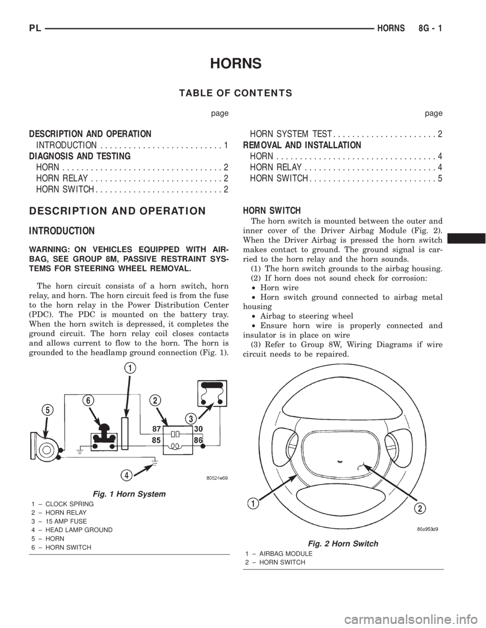
grounded to the headlamp ground connection (Fig. 1).
HORN SWITCH
The horn switch is mounted between the outer and
inner cover of the Driver Airbag Module (Fig. 2).
When the Driver Airbag is pressed the horn switch
makes contact to ground. The ground signal is car-
ried to the horn relay and the horn sounds.
(1) The horn switch grounds to the airbag housing.
(2) If horn does not sound check for corrosion:
²Horn wire
²Horn switch ground connected to airbag metal
housing
²Airbag to steering wheel
²Ensure horn wire is properly connected and
insulator is in place on wire
(3) Refer to Group 8W, Wiring Diagrams if wire
circuit needs to be repaired.
Fig. 1 Horn System
1 ± CLOCK SPRING
2 ± HORN RELAY
3 ± 15 AMP FUSE
4 ± HEAD LAMP GROUND
5 ± HORN
6 ± HORN SWITCH
Fig. 2 Horn Switch
1 ± AIRBAG MODULE
2 ± HORN SWITCH
PLHORNS 8G - 1
Page 281 of 1285
DIAGNOSIS AND TESTING
HORN
(1) Disconnect wire connector at horn.
(2) Using a voltmeter, connect one lead to ground
terminal and the other lead to the positive wire ter-
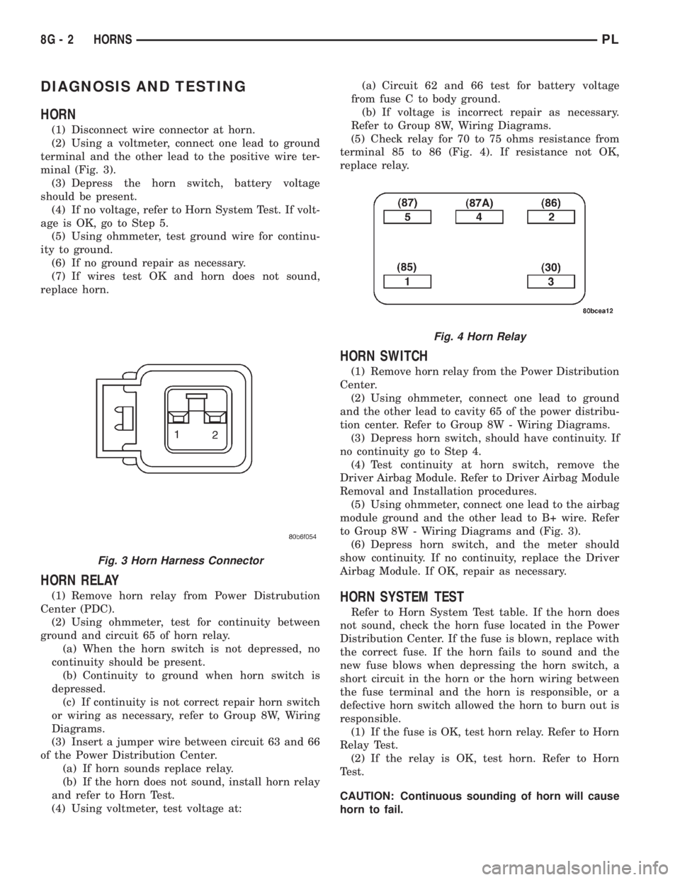
minal (Fig. 3).
(3) Depress the horn switch, battery voltage
should be present.
(4) If no voltage, refer to Horn System Test. If volt-
age is OK, go to Step 5.
(5) Using ohmmeter, test ground wire for continu-
ity to ground.
(6) If no ground repair as necessary.
(7) If wires test OK and horn does not sound,
replace horn.
HORN RELAY
(1) Remove horn relay from Power Distrubution
Center (PDC).
(2) Using ohmmeter, test for continuity between
ground and circuit 65 of horn relay.
(a) When the horn switch is not depressed, no
continuity should be present.
(b) Continuity to ground when horn switch is
depressed.
(c) If continuity is not correct repair horn switch
or wiring as necessary, refer to Group 8W, Wiring
Diagrams.
(3) Insert a jumper wire between circuit 63 and 66
of the Power Distribution Center.
(a) If horn sounds replace relay.
(b) If the horn does not sound, install horn relay
and refer to Horn Test.
(4) Using voltmeter, test voltage at:(a) Circuit 62 and 66 test for battery voltage
from fuse C to body ground.
(b) If voltage is incorrect repair as necessary.
Refer to Group 8W, Wiring Diagrams.
(5) Check relay for 70 to 75 ohms resistance from
terminal 85 to 86 (Fig. 4). If resistance not OK,
replace relay.
HORN SWITCH
(1) Remove horn relay from the Power Distribution
Center.
(2) Using ohmmeter, connect one lead to ground
and the other lead to cavity 65 of the power distribu-
tion center. Refer to Group 8W - Wiring Diagrams.
(3) Depress horn switch, should have continuity. If
no continuity go to Step 4.
(4) Test continuity at horn switch, remove the
Driver Airbag Module. Refer to Driver Airbag Module
Removal and Installation procedures.
(5) Using ohmmeter, connect one lead to the airbag
module ground and the other lead to B+ wire. Refer
to Group 8W - Wiring Diagrams and (Fig. 3).
(6) Depress horn switch, and the meter should
show continuity. If no continuity, replace the Driver
Airbag Module. If OK, repair as necessary.
HORN SYSTEM TEST
Refer to Horn System Test table. If the horn does
not sound, check the horn fuse located in the Power
Distribution Center. If the fuse is blown, replace with
the correct fuse. If the horn fails to sound and the
new fuse blows when depressing the horn switch, a
short circuit in the horn or the horn wiring between
the fuse terminal and the horn is responsible, or a
defective horn switch allowed the horn to burn out is
responsible.
(1) If the fuse is OK, test horn relay. Refer to Horn
Relay Test.
(2) If the relay is OK, test horn. Refer to Horn
Test.
CAUTION: Continuous sounding of horn will cause
horn to fail.
Fig. 3 Horn Harness Connector
Fig. 4 Horn Relay
8G - 2 HORNSPL
Page 282 of 1285
Should the horn sound continuously:
²Unplug the horn relay from Power Distribution
Center.²Refer to Horn Relay Test.
Refer to Group 8W, wiring Diagrams for circuit and
wiring information.
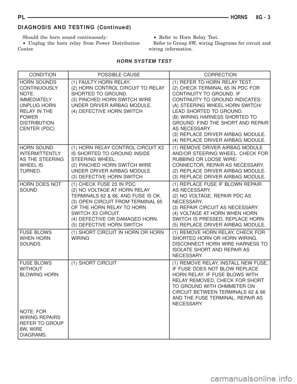
HORN SYSTEM TEST
CONDITION POSSIBLE CAUSE CORRECTION
HORN SOUNDS
CONTINUOUSLY.
NOTE:
IMMEDIATELY
UNPLUG HORN
RELAY IN THE
POWER
DISTRIBUTION
CENTER (PDC)(1) FAULTY HORN RELAY.
(2) HORN CONTROL CIRCUIT TO RELAY
SHORTED TO GROUND.
(3) PINCHED HORN SWITCH WIRE
UNDER DRIVER AIRBAG MODULE.
(4) DEFECTIVE HORN SWITCH(1) REFER TO HORN RELAY TEST.
(2) CHECK TERMINAL 65 IN PDC FOR
CONTINUITY TO GROUND. IF
CONTINUITY TO GROUND INDICATES:
(A) STEERING WHEEL HORN SWITCH/
LEAD SHORTED TO GROUND.
(B) WIRING HARNESS SHORTED TO
GROUND. FIND THE SHORT AND REPAIR
AS NECESSARY.
(3) REPLACE DRIVER AIRBAG MODULE.
(4) REPLACE DRIVER AIRBAG MODULE.
HORN SOUND
INTERMITTENTLY
AS THE STEERING
WHEEL IS
TURNED.(1) HORN RELAY CONTROL CIRCUIT X3
IS SHORTED TO GROUND INSIDE
STEERING WHEEL.
(2) PINCHED HORN SWITCH WIRE
UNDER DRIVER AIRBAG MODULE
(3) DEFECTIVE HORN SWITCH(1) REMOVE DRIVER AIRBAG MODULE
AND/OR STEERING WHEEL. CHECK FOR
RUBBING OR LOOSE WIRE/
CONNECTOR, REPAIR AS NECESSARY.
(2) REPLACE DRIVER AIRBAG MODULE.
(3) REPLACE DRIVER AIRBAG MODULE.
HORN DOES NOT
SOUND(1) CHECK FUSE 23 IN PDC
(2) NO VOLTAGE AT HORN RELAY
TERMINALS 62 & 66, AND FUSE IS OK.
(3) OPEN CIRCUIT FROM TERMINAL 65
OF THE HORN RELAY TO HORN
SWITCH X3 CIRCUIT.
(4) DEFECTIVE OR DAMAGED HORN.
(5) DEFECTIVE HORN SWITCH(1) REPLACE FUSE IF BLOWN REPAIR
AS NECESSARY.
(2) NO VOLTAGE, REPAIR PDC AS
NECESSARY.
(3) REPAIR CIRCUIT AS NECESSARY.
(4) VOLTAGE AT HORN WHEN HORN
SWITCH IS PRESSED, REPLACE HORN.
(5) REPLACE DRIVER AIRBAG MODULE.
FUSE BLOWS
WHEN HORN
SOUNDS(1) SHORT CIRCUIT IN HORN OR HORN
WIRING(1) REMOVE HORN RELAY, CHECK FOR
SHORTED HORN OR HORN WIRING.
DISCONNECT HORN WIRE HARNESS TO
ISOLATE SHORT AND REPAIR AS
NECESSARY.
FUSE BLOWS
WITHOUT
BLOWING HORN(1) SHORT CIRCUIT (1) REMOVE RELAY, INSTALL NEW FUSE,
IF FUSE DOES NOT BLOW REPLACE
HORN RELAY. IF FUSE BLOWS WITH
RELAY REMOVED, CHECK FOR SHORT
TO GROUND WITH OHMMETER ON
CIRCUIT BETWEEN TERMINALS 62 & 66
AND THE FUSE TERMINAL. REPAIR AS
NECESSARY.
NOTE: FOR
WIRING REPAIRS
REFER TO GROUP
8W, WIRE
DIAGRAMS.
PLHORNS 8G - 3
DIAGNOSIS AND TESTING (Continued)
Page 284 of 1285
HORN SWITCH
REMOVAL
(1) Disconnect and isolate the battery negative
cable (Fig. 5).
(2) Remove the Driver Airbag Module. Refer to
Group 8M Passive Restraint Systems, Driver Airbag
Module Removal and Installation.
(3) Clip off strap tie holding the horn switch wire
to the airbag module.
(4) Unclip horn switch wire connector from airbag
module.(5) Remove four torx screws from top side of air-
bag module.
(6) Fold airbag module cover down to expose the
horn switch.
(7) Lift the horn switch off indexing tabs and
remove from vehicle.
INSTALLATION
For installation, reverse the above procedures.
PLHORNS 8G - 5
REMOVAL AND INSTALLATION (Continued)
Page 286 of 1285
VEHICLE SPEED CONTROL SYSTEM
TABLE OF CONTENTS
page page
DESCRIPTION AND OPERATION
SPEED CONTROL SYSTEM.................1
SPEED CONTROL SERVO-PCM OUTPUT.......2
SPEED CONTROL SWITCHESÐPCM INPUT....2
STOP LAMP SWITCH......................3
SERVO CABLE...........................3
VACUUM RESERVOIR.....................3VEHICLE SPEED SENSOR..................3
REMOVAL AND INSTALLATION
SPEED CONTROL SERVO...................3
SPEED CONTROL SWITCH..................4
SPEED CONTROL SERVO CABLE.............4
VACUUM RESERVOIR.....................5
DESCRIPTION AND OPERATION
SPEED CONTROL SYSTEM
OPERATION
The speed control system is electronically con-
trolled and vacuum operated. The electronic control
is integrated into the Powertrain Control Module
which is located in the engine compartment. The con-
trols are located on the steering wheel and consist of
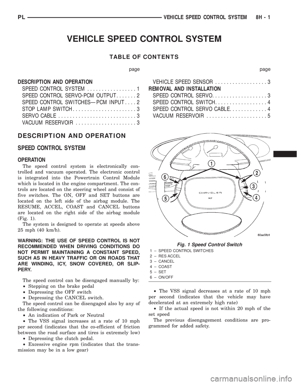
five switches. The ON, OFF and SET buttons are
located on the left side of the airbag module. The
RESUME, ACCEL, COAST and CANCEL buttons
are located on the right side of the airbag module
(Fig. 1).
The system is designed to operate at speeds above
25 mph (40 km/h).
WARNING: THE USE OF SPEED CONTROL IS NOT
RECOMMENDED WHEN DRIVING CONDITIONS DO
NOT PERMIT MAINTAINING A CONSTANT SPEED,
SUCH AS IN HEAVY TRAFFIC OR ON ROADS THAT
ARE WINDING, ICY, SNOW COVERED, OR SLIP-
PERY.
The speed control can be disengaged manually by:
²Stepping on the brake pedal
²Depressing the OFF switch
²Depressing the CANCEL switch.
The speed control can be disengaged also by any of
the following conditions:
²An indication of Park or Neutral
²The VSS signal increases at a rate of 10 mph
per second (indicates that the co-efficient of friction
between the road surface and tires is extremely low)
²Depressing the clutch pedal.
²Excessive engine rpm (indicates that the trans-
mission may be in a low gear)²The VSS signal decreases at a rate of 10 mph
per second (indicates that the vehicle may have
decelerated at an extremely high rate)
²If the actual speed is not within 20 mph of the
set speed
The previous disengagement conditions are pro-
grammed for added safety.
Fig. 1 Speed Control Switch
1 ± SPEED CONTROL SWITCHES
2 ± RES ACCEL
3 ± CANCEL
4 ± COAST
5 ± SET
6 ± ON/OFF
PLVEHICLE SPEED CONTROL SYSTEM 8H - 1
Page 289 of 1285
INSTALLATION
(1) Install retaining clip to cable at servo.
(2) Install 2 nuts at cable to servo and servo
bracket, tighten to 7 N´m (60 ins. lbs.).
(3) Connect electrical connector to servo.
(4) Connect vacuum hose to servo
SPEED CONTROL SWITCH
The speed control switches are mounted in the
steering wheel and wired through the clock spring
device under the airbag module (Fig. 1).
WARNING: IF REMOVAL OF AIRBAG MODULE IS
NECESSARY, REFER TO THE RESTRAINT SYS-
TEMS.
REMOVAL
(1) Turn off ignition.
(2) Remove two screws from side of each switch.
(3) Rock switch away from airbag and steering
wheel.
(4) Disconnect two-way electrical connector.
(5) Repeat for the other switch.
INSTALLATION
(1) Install switches.
(2) Connect two-way electrical connector.
(3) Install two screws to the side of each switch.
(4) Install airbag, refer to the Restraint Systems
SPEED CONTROL SERVO CABLE
REMOVAL
(1) Disconnect the negative battery cable.
(2) Remove the throttle cable cover.
(3) Remove speed control cable from throttle lever
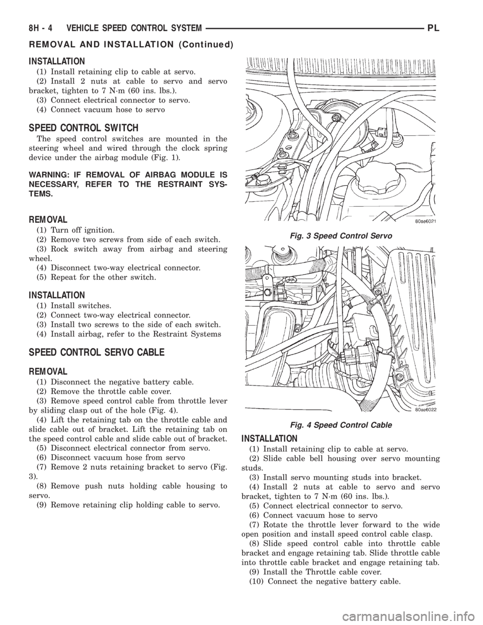
by sliding clasp out of the hole (Fig. 4).
(4) Lift the retaining tab on the throttle cable and
slide cable out of bracket. Lift the retaining tab on
the speed control cable and slide cable out of bracket.
(5) Disconnect electrical connector from servo.
(6) Disconnect vacuum hose from servo
(7) Remove 2 nuts retaining bracket to servo (Fig.
3).
(8) Remove push nuts holding cable housing to
servo.
(9) Remove retaining clip holding cable to servo.
INSTALLATION
(1) Install retaining clip to cable at servo.
(2) Slide cable bell housing over servo mounting
studs.
(3) Install servo mounting studs into bracket.
(4) Install 2 nuts at cable to servo and servo
bracket, tighten to 7 N´m (60 ins. lbs.).
(5) Connect electrical connector to servo.
(6) Connect vacuum hose to servo
(7) Rotate the throttle lever forward to the wide
open position and install speed control cable clasp.
(8) Slide speed control cable into throttle cable
bracket and engage retaining tab. Slide throttle cable
into throttle cable bracket and engage retaining tab.
(9) Install the Throttle cable cover.
(10) Connect the negative battery cable.
Fig. 3 Speed Control Servo
Fig. 4 Speed Control Cable
8H - 4 VEHICLE SPEED CONTROL SYSTEMPL
REMOVAL AND INSTALLATION (Continued)
Page 292 of 1285
TURN SIGNAL and HAZARD WARNING SYSTEMS
TABLE OF CONTENTS
page page
GENERAL INFORMATION
INTRODUCTION..........................1
DESCRIPTION AND OPERATION
HAZARD WARNING SYSTEM................2
HEADLAMP SWITCH......................2
COMBINATION FLASHER...................2DIAGNOSIS AND TESTING
MULTI-FUNCTION SWITCH.................3
REMOVAL AND INSTALLATION
COMBINATION FLASHER...................5
MULTI-FUNCTION SWITCH.................5
GENERAL INFORMATION
INTRODUCTION
WARNING: ON VEHICLES EQUIPPED WITH AIR-
BAG, SEE GROUP 8M, PASSIVE RESTRAINT SYS-
TEMS FOR AIRBAG REMOVAL.
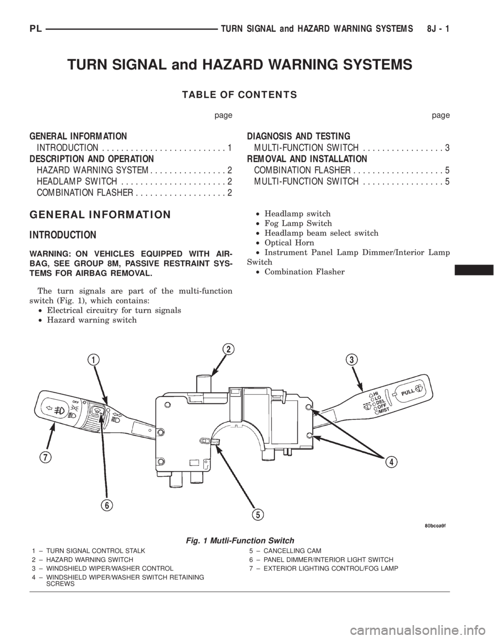
The turn signals are part of the multi-function
switch (Fig. 1), which contains:
²Electrical circuitry for turn signals
²Hazard warning switch²Headlamp switch
²Fog Lamp Switch
²Headlamp beam select switch
²Optical Horn
²Instrument Panel Lamp Dimmer/Interior Lamp
Switch
²Combination Flasher
Fig. 1 Mutli-Function Switch
1 ± TURN SIGNAL CONTROL STALK
2 ± HAZARD WARNING SWITCH
3 ± WINDSHIELD WIPER/WASHER CONTROL
4 ± WINDSHIELD WIPER/WASHER SWITCH RETAINING
SCREWS5 ± CANCELLING CAM
6 ± PANEL DIMMER/INTERIOR LIGHT SWITCH
7 ± EXTERIOR LIGHTING CONTROL/FOG LAMP
PLTURN SIGNAL and HAZARD WARNING SYSTEMS 8J - 1
Page 324 of 1285
BULB APPLICATION
TABLE OF CONTENTS
page page
SPECIFICATIONS
EXTERIOR LAMPS........................17INTERIOR LAMPS........................17
SPECIFICATIONS
EXTERIOR LAMPS
CAUTION: Do not use bulbs that have a higher can-
dle power than the bulb listed in the chart below.
Damage to lamp can result. Do not touch halogen
bulbs with fingers or other oily surfaces. Bulb life
will be reduced.
LAMP BULB
Back Up Lamp................3157 ± P27/7W
Center High Mounted Stop Lamp
(CHMSL).........................W16W
Front Fog Lamp..................... GE881
Front Park/Turn Signal Lamp..........3157NA
Front Side Marker Lamp................. 168
Headlamp............................9007
License Plate Lamp..................... 168
Rear Tail/Stop/
Turn Signal Lamp............3157 ± P27/7W
INTERIOR LAMPS
Service procedures for most of the lamps in the
instrument panel, Instrument cluster and switches
are located in Group 8E, Instrument Panel and
Gauges.
CAUTION: Do not use bulbs that have a higher can-
dle power than the bulb listed in the chart below.
Damage to lamp can result.LAMP BULB
ABS Indicator......................... LED
Airbag Indicator....................... LED
Brake System Warning Indicator.......... LED
Climate Controls....................... LED
Console Gear Selector W/Auto...........PC194
Dome Lamp..........................T579
Floor Console Lamp..................... T37
Front Fog Lamp Indicator................ LED
Glove Compartment....................T194
High Beam Lamp Indicator.............PC194
Ignition Lock........................... 161
Instrument Cluster Illumination.........PC194
Low Fuel Indicator..................... LED
Low Oil Pressure Indicator............... LED
Rear Cargo...........................T906
Seat Belt Indicator..................... LED
Security Alarm Indicator................. LED
Malfunction Indicator Light.............. LED
TRAC OFF Indicator.................... LED
Turn Signal Indicator..................PC194
Underhood............................ 105
Visor Vanity........................6501966
Voltage Indicator....................... LED
All the inside bulbs brass or glass wedge base. Alu-
minum base bulbs are not approved and should not
be used for replacement.
PLLAMPS 8L - 17