2000 DODGE NEON check engine light
[x] Cancel search: check engine lightPage 194 of 1285
WATER PUMP DIAGNOSIS
A quick flow test to tell whether or not the pump is
working is to see if the heater warms properly. A
defective pump will not be able to circulate heated
coolant through the long heater hose.
Another flow test to help determine pump opera-
tion:
WARNING: DO NOT remove radiator cap if the cool-
ing system is hot or under pressure.
(1) Remove cooling system pressure cap.
(2) Remove a small amount of coolant from the
system.
(3) Start the engine and warm up until thermostat
opens.
(4) With the thermostat open and coolant level low,
visually inspect for coolant flow. If flow is present,
the water pump is pumping coolant through the sys-
tem.
COOLING SYSTEM FLOW CHECK
To determine whether coolant is flowing through
the cooling system, use the following procedures:
(1) If engine is cold, idle engine until normal oper-
ating temperature is reached. Then feel the upper
radiator hose. If it is hot, coolant is circulating.
WARNING: DO NOT REMOVE THE COOLING SYS-
TEM PRESSURE CAP WITH THE SYSTEM HOT AND
UNDER PRESSURE BECAUSE SERIOUS BURNS
FROM COOLANT CAN OCCUR.
(2) Remove pressure cap when engine is cold,
remove small amount of coolant Idle engine until
thermostat opens, you should observe coolant flow
while looking down the filler neck. Once flow is
detected install the pressure cap.
ELECTRIC FAN MOTOR TEST
Refer to Powertrain Diagnostic Manual for proce-
dure.
COOLANT CONCENTRATION TESTING
Coolant concentration should be checked when any
additional coolant was added to system or after a
coolant drain, flush and refill. The coolant mixture
offers optimum engine cooling and protection against
corrosion when mixed to a freeze point of -37ÉC
(-34ÉF) to -59ÉC (-50ÉF). The use of a hydrometer or a
refractometer can be used to test coolant concentra-
tion.
A hydrometer will test the amount of glycol in a
mixture by measuring the specific gravity of the mix-
ture. The higher the concentration of ethylene glycol,
the larger the number of balls that will float, andhigher the freeze protection (up to a maximum of
70% by volume glycol).
A refractometer will test the amount of glycol in a
coolant mixture by measuring the amount a beam of
light bends as it passes through the fluid.
Some coolant manufactures use other types of gly-
cols into their coolant formulations. Propylene glycol
is the most common new coolant. However, propylene
glycol based coolants do not provide the same freez-
ing protection and corrosion protection and is only
recommended for limited usage. Refer to appropriate
Technical Service Bulletin(s) regarding use of propy-
lene glycol based coolants.
CAUTION: Do not mix types of coolantÐcorrosion
protection will be severely reduced.
Because ethylene glycol and propylene glycol do
not have the same specific gravities, the use of a
hydrometer will be inaccurate. Therefore, Special
Tool 8286 refractometer, is recommended when test-
ing either ethylene or propylene glycol coolants.
TESTING COOLING SYSTEM FOR LEAKS
The system should be full. With the engine not
running, wipe the filler neck sealing seat clean.
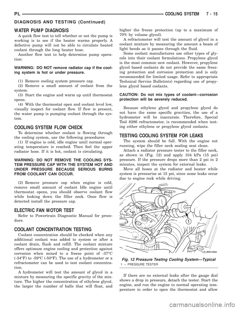
Attach a radiator pressure tester to the filler neck,
as shown in (Fig. 12) and apply 104 kPa (15 psi)
pressure. If the pressure drops more than 2 psi in 2
minutes, inspect the system for external leaks.
Move all hoses at the radiator and heater while
system is pressurize at 15 psi, since some leaks occur
due to engine rock while driving.
If there are no external leaks after the gauge dial
shows a drop in pressure, detach the tester. Start the
engine, and run the engine to normal operating tem-
perature in order to open the thermostat and allow
Fig. 12 Pressure Testing Cooling SystemÐTypical
1 ± PRESSURE TESTER
PLCOOLING SYSTEM 7 - 15
DIAGNOSIS AND TESTING (Continued)
Page 196 of 1285
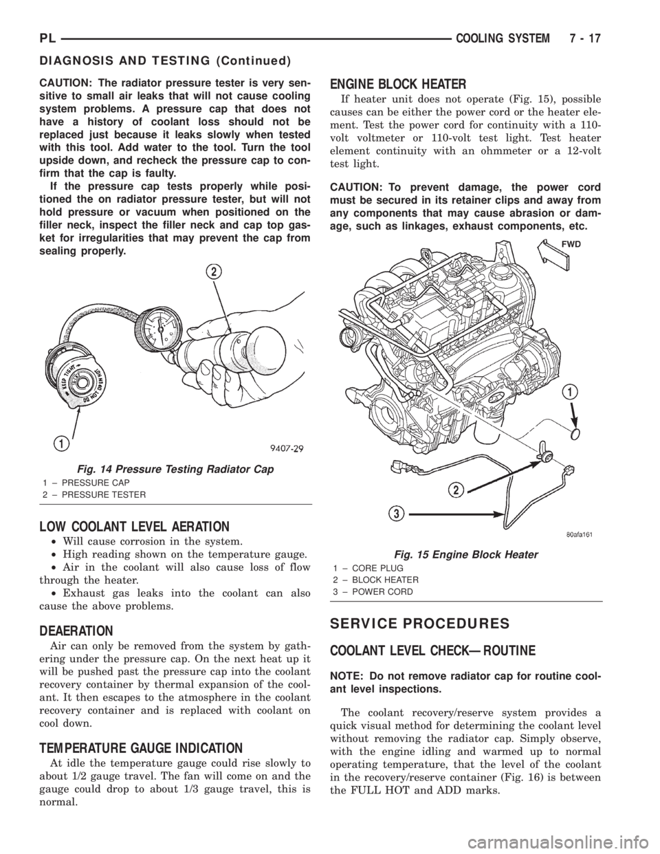
CAUTION: The radiator pressure tester is very sen-
sitive to small air leaks that will not cause cooling
system problems. A pressure cap that does not
have a history of coolant loss should not be
replaced just because it leaks slowly when tested
with this tool. Add water to the tool. Turn the tool
upside down, and recheck the pressure cap to con-
firm that the cap is faulty.
If the pressure cap tests properly while posi-
tioned the on radiator pressure tester, but will not
hold pressure or vacuum when positioned on the
filler neck, inspect the filler neck and cap top gas-
ket for irregularities that may prevent the cap from
sealing properly.
LOW COOLANT LEVEL AERATION
²Will cause corrosion in the system.
²High reading shown on the temperature gauge.
²Air in the coolant will also cause loss of flow
through the heater.
²Exhaust gas leaks into the coolant can also
cause the above problems.
DEAERATION
Air can only be removed from the system by gath-
ering under the pressure cap. On the next heat up it
will be pushed past the pressure cap into the coolant
recovery container by thermal expansion of the cool-
ant. It then escapes to the atmosphere in the coolant
recovery container and is replaced with coolant on
cool down.
TEMPERATURE GAUGE INDICATION
At idle the temperature gauge could rise slowly to
about 1/2 gauge travel. The fan will come on and the
gauge could drop to about 1/3 gauge travel, this is
normal.
ENGINE BLOCK HEATER
If heater unit does not operate (Fig. 15), possible
causes can be either the power cord or the heater ele-
ment. Test the power cord for continuity with a 110-
volt voltmeter or 110-volt test light. Test heater
element continuity with an ohmmeter or a 12-volt
test light.
CAUTION: To prevent damage, the power cord
must be secured in its retainer clips and away from
any components that may cause abrasion or dam-
age, such as linkages, exhaust components, etc.
SERVICE PROCEDURES
COOLANT LEVEL CHECKÐROUTINE
NOTE: Do not remove radiator cap for routine cool-
ant level inspections.
The coolant recovery/reserve system provides a
quick visual method for determining the coolant level
without removing the radiator cap. Simply observe,
with the engine idling and warmed up to normal
operating temperature, that the level of the coolant
in the recovery/reserve container (Fig. 16) is between
the FULL HOT and ADD marks.
Fig. 14 Pressure Testing Radiator Cap
1 ± PRESSURE CAP
2 ± PRESSURE TESTER
Fig. 15 Engine Block Heater
1 ± CORE PLUG
2 ± BLOCK HEATER
3 ± POWER CORD
PLCOOLING SYSTEM 7 - 17
DIAGNOSIS AND TESTING (Continued)
Page 197 of 1285
COOLANTÐADDING ADDITIONAL
NOTE: The radiator cap should not be removed.
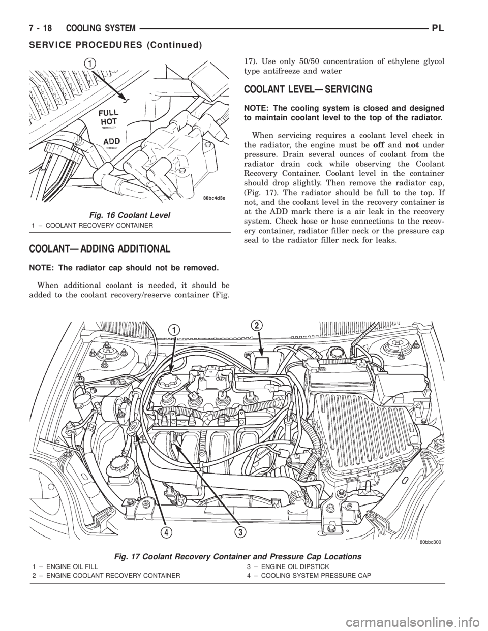
When additional coolant is needed, it should be
added to the coolant recovery/reserve container (Fig.17). Use only 50/50 concentration of ethylene glycol
type antifreeze and water
COOLANT LEVELÐSERVICING
NOTE: The cooling system is closed and designed
to maintain coolant level to the top of the radiator.
When servicing requires a coolant level check in
the radiator, the engine must beoffandnotunder
pressure. Drain several ounces of coolant from the
radiator drain cock while observing the Coolant
Recovery Container. Coolant level in the container
should drop slightly. Then remove the radiator cap,
(Fig. 17). The radiator should be full to the top. If
not, and the coolant level in the recovery container is
at the ADD mark there is a air leak in the recovery
system. Check hose or hose connections to the recov-
ery container, radiator filler neck or the pressure cap
seal to the radiator filler neck for leaks.
Fig. 17 Coolant Recovery Container and Pressure Cap Locations
1 ± ENGINE OIL FILL
2 ± ENGINE COOLANT RECOVERY CONTAINER3 ± ENGINE OIL DIPSTICK
4 ± COOLING SYSTEM PRESSURE CAP
Fig. 16 Coolant Level
1 ± COOLANT RECOVERY CONTAINER
7 - 18 COOLING SYSTEMPL
SERVICE PROCEDURES (Continued)
Page 214 of 1285
be checked. To determine if a high current draw con-
dition exists first check the vehicle with a test lamp.
(1) Verify that all electrical accessories are OFF.
²Remove key from ignition switch
²Turn off all lights
²Trunk lid is closed
²Engine compartment hood lamp is disconnected
or lamp removed
²Map lamp on rear view mirror
²Glove box door is closed
²Sun visor vanity lights are OFF
²All doors are closed
²Allow the ignition key lamp system to time out
in approximately 30 seconds, if equipped.
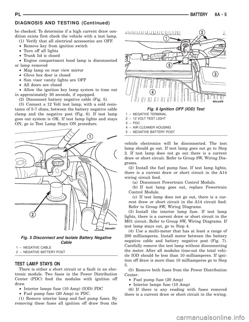
(2) Disconnect battery negative cable (Fig. 5).
(3) Connect a 12 Volt test lamp, with a cold resis-
tance of 5-7 ohms, between the battery negative cable
clamp and the negative post (Fig. 6). If test lamp
goes out system is OK. If test lamp lights and stays
ON, go to Test Lamp Stays ON procedure.
TEST LAMP STAYS ON
There is either a short circuit or a fault in an elec-
tronic module. Two fuses in the Power Distribution
Center (PDC) feed the modules with ignition off
draw.
²Interior lamps fuse (10 Amp) (IOD) PDC
²Fuel pump fuse (20 Amp) in PDC.
(1) Remove interior lamp and fuel pump fuses. By
removing these fuses all ignition off draw from thevehicle electronics will be disconnected. The test
lamp should go out. If test lamp goes out go to Step
2. If test lamp does not go out there is a current
draw or short circuit. Refer to Group 8W, Wiring Dia-
grams.
(2) Install the fuel pump fuse. If test lamp lights,
there is a current draw or short circuit in the A14
wiring circuit feed.
(a) Disconnect Powertrain Control Module.
(b) If test lamp goes out, replace Powertrain
Control Module.
(c) If test lamp does not go out, there is a cur-
rent draw or short circuit in the A14 circuit feed.
Refer to Group 8W, Wiring Diagrams.
(3) Install the interior lamp fuse. If test lamp
lights, there is a current draw or short circuit in the
M01 circuit. Refer to Group 8W, Wiring Diagrams. If
test lamp stays out, go to Step 4.
(4) Use a multi-meter that has at least a range of
200 milliamperes. Install meter between the battery
negative cable and battery negative post (Fig. 7).
Carefully remove the test lamp without disconnecting
the meter. After all modules time-out the total vehi-
cle IOD should be less than 10 milliamperes. If igni-
tion off draw is more than 10 milliamperes go to Step
5.
(5) Remove both fuses from the Power Distribution
Center:
²Fuel pump fuse (20 Amp)
²Interior lamps fuse (10 Amp)
(6) If there is any reading with fuses removed
there is a current draw or short circuit in the wiring.
Fig. 5 Disconnect and Isolate Battery Negative
Cable
1 ± NEGATIVE CABLE
2 ± NEGATIVE BATTERY POST
Fig. 6 Ignition OFF (IOD) Test
1 ± NEGATIVE TERMINAL
2 ± 12 VOLT TEST LIGHT
3 ± PDC
4 ± AIR CLEANER HOUSING
5 ± NEGATIVE BATTERY POST
PLBATTERY 8A - 5
DIAGNOSIS AND TESTING (Continued)
Page 226 of 1285
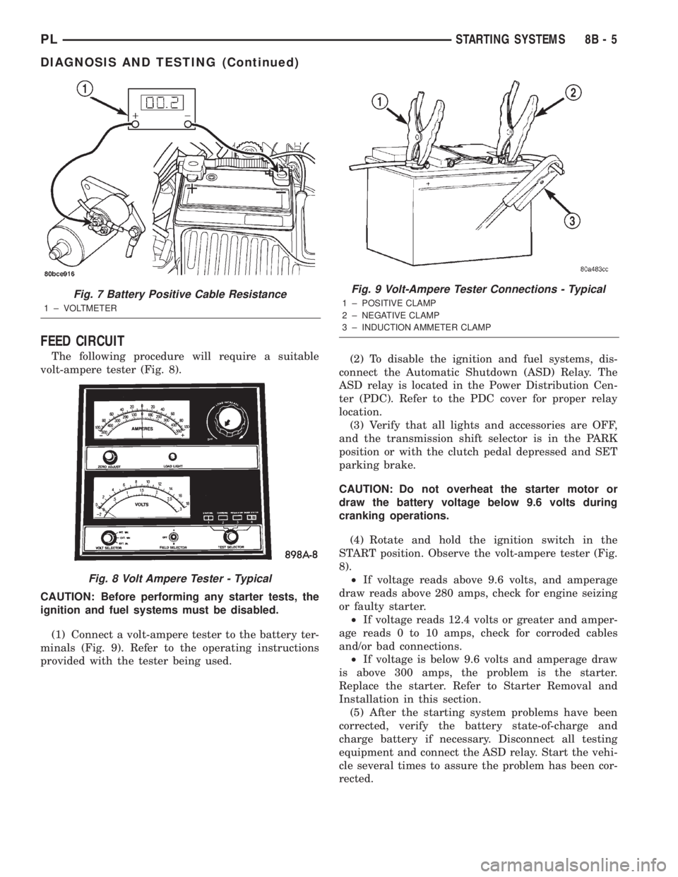
FEED CIRCUIT
The following procedure will require a suitable
volt-ampere tester (Fig. 8).
CAUTION: Before performing any starter tests, the
ignition and fuel systems must be disabled.
(1) Connect a volt-ampere tester to the battery ter-
minals (Fig. 9). Refer to the operating instructions
provided with the tester being used.(2) To disable the ignition and fuel systems, dis-
connect the Automatic Shutdown (ASD) Relay. The
ASD relay is located in the Power Distribution Cen-
ter (PDC). Refer to the PDC cover for proper relay
location.
(3) Verify that all lights and accessories are OFF,
and the transmission shift selector is in the PARK
position or with the clutch pedal depressed and SET
parking brake.
CAUTION: Do not overheat the starter motor or
draw the battery voltage below 9.6 volts during
cranking operations.
(4) Rotate and hold the ignition switch in the
START position. Observe the volt-ampere tester (Fig.
8).
²If voltage reads above 9.6 volts, and amperage
draw reads above 280 amps, check for engine seizing
or faulty starter.
²If voltage reads 12.4 volts or greater and amper-
age reads 0 to 10 amps, check for corroded cables
and/or bad connections.
²If voltage is below 9.6 volts and amperage draw
is above 300 amps, the problem is the starter.
Replace the starter. Refer to Starter Removal and
Installation in this section.
(5) After the starting system problems have been
corrected, verify the battery state-of-charge and
charge battery if necessary. Disconnect all testing
equipment and connect the ASD relay. Start the vehi-
cle several times to assure the problem has been cor-
rected.
Fig. 7 Battery Positive Cable Resistance
1 ± VOLTMETER
Fig. 8 Volt Ampere Tester - Typical
Fig. 9 Volt-Ampere Tester Connections - Typical
1 ± POSITIVE CLAMP
2 ± NEGATIVE CLAMP
3 ± INDUCTION AMMETER CLAMP
PLSTARTING SYSTEMS 8B - 5
DIAGNOSIS AND TESTING (Continued)
Page 249 of 1285
DESCRIPTION AND OPERATION
HEADLAMP SWITCH
The headlamp switch is part of the Multi-Function
Switch. Refer to Group 8J, Turn Signal and Flasher
for the Multi-Function Switch Test, Removal and
Installation procedures.
INSTRUMENT CLUSTER
There are two conventional instrument cluster
assemblies available. The clusters electronically drive
the speedometer, odometer, gauges, and tachometer
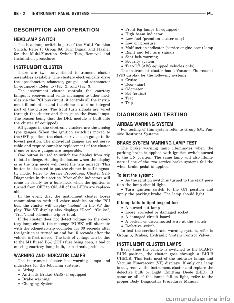
(if equipped). Refer to (Fig. 2) and (Fig. 3).
The instrument cluster controls the courtesy
lamps, it receives and sends messages to other mod-
ules via the PCI bus circuit, it controls all the instru-
ment illumination and the chime is also an integral
part of the cluster. The front turn signals are wired
through the cluster and then go to the front lamps.
The reason being that the DRL module is built into
the cluster (if equipped).
All gauges in the electronic clusters are the analog
type gauges. When the ignition switch is moved to
the OFF position, the cluster drives each gauge to its
lowest position. The individual gauges are not servi-
cable and require complete replacement of the cluster
if one or more gauges are inoperable.
One button is used to switch the display from trip
to total mileage. Holding the button when the display
is in the trip mode will reset the trip mileage. This
button is also used to put the cluster in self-diagnos-
tic mode. Refer to Service Procedures, Cluster Self-
Diagnostics in this section. Most of the indicators will
come on briefly for a bulb heck when the ignition is
turned from OFF to ON. All of the LED's are replace-
able.
In the event that the instrument cluster looses
communication with all other modules on the PCI
bus, the cluster will display ªnobusº in the VF dis-
play. The VF display also displays ªDoorº, ªCruiseº,
ªTracº, and odometer trip or total.
If the cluster does not detect voltage on the cour-
tesy lamp circuit, the message ªFUSEº will alternate
with the odometer/trip odometer for 30 seconds after
the ignition is turned on and for 15 seconds after the
vehicle is first moved. The lack of voltage can be due
to the M1 Fused B(+) (IOD) fuse being open, a bad or
missing courtesy lamp bulb, or a circuit problem.
WARNING AND INDICATOR LAMPS
The instrument cluster has warning lamps and
indicators for the following systems:
²Airbag
²Anti-lock Brakes (ABS) if equipped
²Brake warning
²Charging System²Front fog lamps (if equipped)
²High beam indicator
²Low fuel (premium cluster only)
²Low oil pressure
²Malfunction indicator (service engine soon) lamp
²Right and left turn signals
²Seat belt warning
²Security system
²Trac-Off (ABS equipped vehicles only)
The instrument cluster has a Vacuum Fluorescent
(VF) display for the following systems:
²Cruise
²Door (ajar)
²Odometer
²Set (cruise)
²Trac
²Trip
DIAGNOSIS AND TESTING
AIRBAG WARNING SYSTEM
For testing of this system refer to Group 8M, Pas-
sive Restraint Systems.
BRAKE SYSTEM WARNING LAMP TEST
The brake warning lamp illuminates when the
parking brake is applied with ignition switch turned
to the ON position. The same lamp will also illumi-
nate if one of the two service brake systems fail the
when brake pedal is applied.
To test the system:
²As the ignition switch is turned to the start posi-
tion the lamp should light.
²Turn ignition switch to the ON position and
apply the parking brake. The lamp should light.
If lamp fails to light inspect for:
²A burned out lamp
²Loose, corroded or damaged socket
²A damaged circuit board
²A broken or disconnected wire at the switch
²Defective switch
To test the service brake warning system, refer to
Group 5, Brakes, Hydraulic System Control Valves.
INSTRUMENT CLUSTER LAMPS
Every time the vehicle is switched to the START/
RUN position, the cluster goes through a BULB
CHECK. This tests most of the indicator lamps and
Vacuum Fluorescent (VF) displays. If only one lamp
is out, remove the instrument cluster and replace the
defective bulb or Light Emitting Diode (LED). If
some or all of the lamps fail to light, refer to the
proper Body Diagnostics Procedures Manual.
8E - 2 INSTRUMENT PANEL SYSTEMSPL
Page 250 of 1285
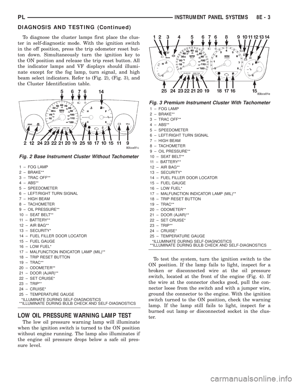
To diagnose the cluster lamps first place the clus-
ter in self-diagnostic mode. With the ignition switch
in the off position, press the trip odometer reset but-
ton down. Simultaneously turn the ignition key to
the ON position and release the trip reset button. All
the indicator lamps and VF displays should illumi-
nate except for the fog lamp, turn signal, and high
beam select indicators. Refer to (Fig. 2), (Fig. 3), and
the Cluster Identification table.
1 ± FOG LAMP
2 ± BRAKE**
3 ± TRAC OFF**
4 ± ABS**
5 ± SPEEDOMETER
6 ± LEFT/RIGHT TURN SIGNAL
7 ± HIGH BEAM
8 ± TACHOMETER
9 ± OIL PRESSURE**
10 ± SEAT BELT**
11 ± BATTERY**
12 ± AIR BAG**
13 ± SECURITY*
14 ± FUEL FILLER DOOR LOCATOR
15 ± FUEL GAUGE
16 ± LOW FUEL*
17 ± MALFUNCTION INDICATOR LAMP (MIL)**
18 ± TRIP RESET BUTTON
19 ± TRAC**
20 ± ODOMETER**
21 ± DOOR (AJAR)**
22 ± SET CRUISE*
23 ± TRIP**
24 ± CRUISE*
25 ± TEMPERATURE GAUGE
*ILLUMINATE DURING SELF-DIAGNOSTICS
**ILLUMINATE DURING BULB CHECK AND SELF-DIAGNOSTICS
LOW OIL PRESSURE WARNING LAMP TEST
The low oil pressure warning lamp will illuminate
when the ignition switch is turned to the ON position
without engine running. The lamp also illuminates if
the engine oil pressure drops below a safe oil pres-
sure level.To test the system, turn the ignition switch to the
ON position. If the lamp fails to light, inspect for a
broken or disconnected wire at the oil pressure
switch, located at the front of the engine (Fig. 4). If
the wire at the connector checks good, pull the con-
nector loose from the switch and with a jumper wire,
ground the connector to the engine. With the ignition
switch turned to the ON position, check the warning
lamp. If the lamp still fails to light, inspect for a
burned out lamp or disconnected socket in the clus-
ter.
Fig. 2 Base Instrument Cluster Without Tachometer
Fig. 3 Premium Instrument Cluster With Tachometer
1 ± FOG LAMP
2 ± BRAKE**
3 ± TRAC OFF**
4 ± ABS**
5 ± SPEEDOMETER
6 ± LEFT/RIGHT TURN SIGNAL
7 ± HIGH BEAM
8 ± TACHOMETER
9 ± OIL PRESSURE**
10 ± SEAT BELT**
11 ± BATTERY**
12 ± AIR BAG**
13 ± SECURITY*
14 ± FUEL FILLER DOOR LOCATOR
15 ± FUEL GAUGE
16 ± LOW FUEL*
17 ± MALFUNCTION INDICATOR LAMP (MIL)**
18 ± TRIP RESET BUTTON
19 ± TRAC**
20 ± ODOMETER**
21 ± DOOR (AJAR)**
22 ± SET CRUISE*
23 ± TRIP**
24 ± CRUISE*
25 ± TEMPERATURE GAUGE
*ILLUMINATE DURING SELF-DIAGNOSTICS
**ILLUMINATE DURING BULB CHECK AND SELF-DIAGNOSTICS
PLINSTRUMENT PANEL SYSTEMS 8E - 3
DIAGNOSIS AND TESTING (Continued)
Page 251 of 1285
MULTIPLE/INDIVIDUAL GAUGES INOPERATIVE
Test speedometer, tachometer and other gauges for
malfunction:
(1) Remove the cluster. Refer to Cluster Removal
and Installation.
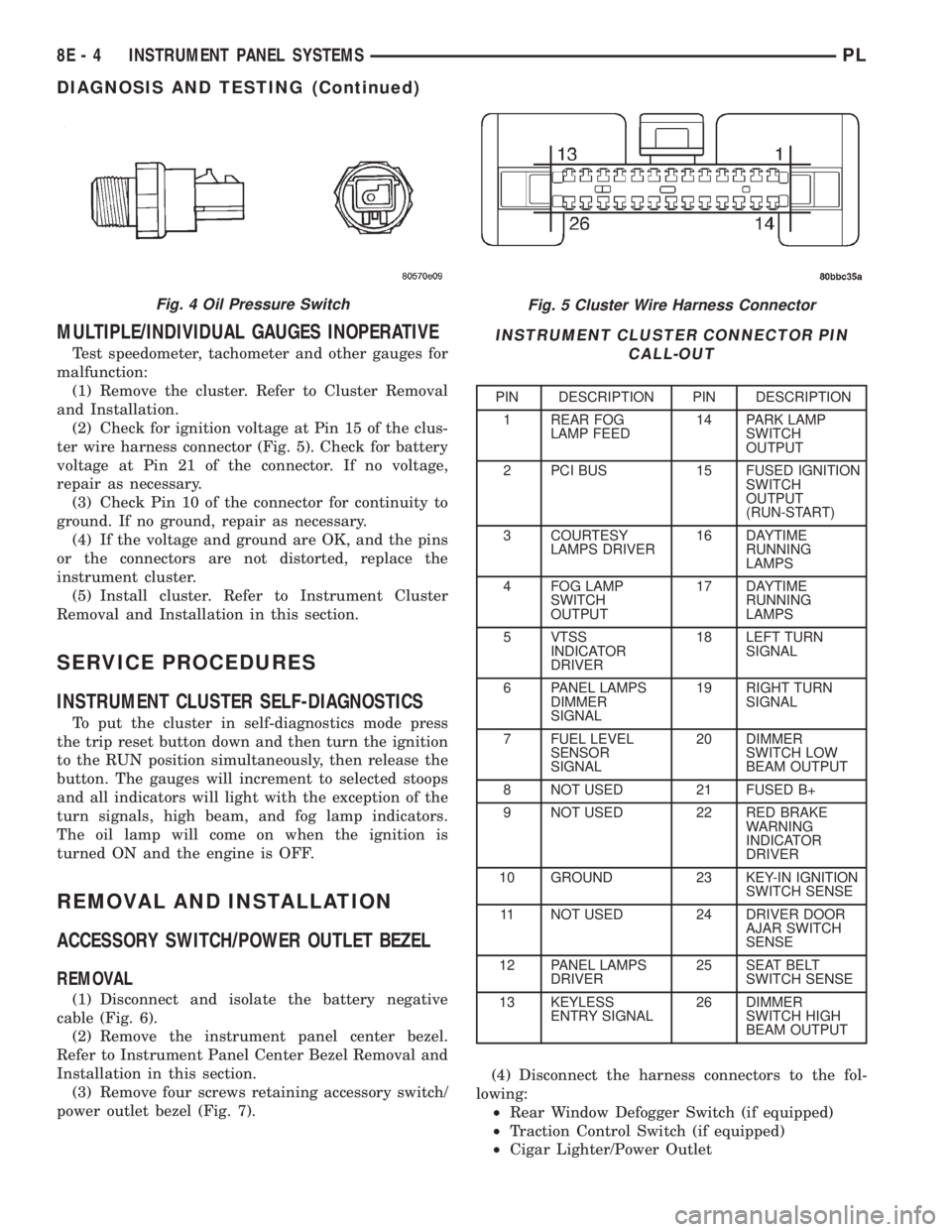
(2) Check for ignition voltage at Pin 15 of the clus-
ter wire harness connector (Fig. 5). Check for battery
voltage at Pin 21 of the connector. If no voltage,
repair as necessary.
(3) Check Pin 10 of the connector for continuity to
ground. If no ground, repair as necessary.
(4) If the voltage and ground are OK, and the pins
or the connectors are not distorted, replace the
instrument cluster.
(5) Install cluster. Refer to Instrument Cluster
Removal and Installation in this section.
SERVICE PROCEDURES
INSTRUMENT CLUSTER SELF-DIAGNOSTICS
To put the cluster in self-diagnostics mode press
the trip reset button down and then turn the ignition
to the RUN position simultaneously, then release the
button. The gauges will increment to selected stoops
and all indicators will light with the exception of the
turn signals, high beam, and fog lamp indicators.
The oil lamp will come on when the ignition is
turned ON and the engine is OFF.
REMOVAL AND INSTALLATION
ACCESSORY SWITCH/POWER OUTLET BEZEL
REMOVAL
(1) Disconnect and isolate the battery negative
cable (Fig. 6).
(2) Remove the instrument panel center bezel.
Refer to Instrument Panel Center Bezel Removal and
Installation in this section.
(3) Remove four screws retaining accessory switch/
power outlet bezel (Fig. 7).(4) Disconnect the harness connectors to the fol-
lowing:
²Rear Window Defogger Switch (if equipped)
²Traction Control Switch (if equipped)
²Cigar Lighter/Power Outlet
Fig. 5 Cluster Wire Harness Connector
INSTRUMENT CLUSTER CONNECTOR PIN
CALL-OUT
PIN DESCRIPTION PIN DESCRIPTION
1 REAR FOG
LAMP FEED14 PARK LAMP
SWITCH
OUTPUT
2 PCI BUS 15 FUSED IGNITION
SWITCH
OUTPUT
(RUN-START)
3 COURTESY
LAMPS DRIVER16 DAYTIME
RUNNING
LAMPS
4 FOG LAMP
SWITCH
OUTPUT17 DAYTIME
RUNNING
LAMPS
5 VTSS
INDICATOR
DRIVER18 LEFT TURN
SIGNAL
6 PANEL LAMPS
DIMMER
SIGNAL19 RIGHT TURN
SIGNAL
7 FUEL LEVEL
SENSOR
SIGNAL20 DIMMER
SWITCH LOW
BEAM OUTPUT
8 NOT USED 21 FUSED B+
9 NOT USED 22 RED BRAKE
WARNING
INDICATOR
DRIVER
10 GROUND 23 KEY-IN IGNITION
SWITCH SENSE
11 NOT USED 24 DRIVER DOOR
AJAR SWITCH
SENSE
12 PANEL LAMPS
DRIVER25 SEAT BELT
SWITCH SENSE
13 KEYLESS
ENTRY SIGNAL26 DIMMER
SWITCH HIGH
BEAM OUTPUT
Fig. 4 Oil Pressure Switch
8E - 4 INSTRUMENT PANEL SYSTEMSPL
DIAGNOSIS AND TESTING (Continued)