2000 DODGE NEON electrical
[x] Cancel search: electricalPage 367 of 1285

REMOTE KEYLESS ENTRY (RKE)
TABLE OF CONTENTS
page page
DESCRIPTION AND OPERATION
INTRODUCTION..........................4
REMOTE KEYLESS ENTRY SYSTEM..........5
REMOTE KEYLESS ENTRY TRANSMITTER.....5
HORN CHIRP TOGGLE.....................5
DIAGNOSIS AND TESTING
REMOTE KEYLESS ENTRY MODULE..........5
DECKLID RELEASE SOLENOID...............5
SERVICE PROCEDURES
HORN CHIRP TOGGLE.....................5SWITCHING OPERATING MODES/
CONFIGURING A NEW MODULE............6
TRANSMITTER PROGRAMMING..............6
REMOVAL AND INSTALLATION
DECK LID RELEASE SOLENOID..............6
REMOTE KEYLESS ENTRY MODULE..........6
SPECIFICATIONS
TRANSMITTER BATTERY...................7
TRANSMITTER RANGE.....................7
DESCRIPTION AND OPERATION
INTRODUCTION
The system allows locking and unlocking of vehicle
door(s), deck lid release, and panic by remote control
using a hand held radio frequency transmitter (Fig.
1). The module must be in the customer usage mode
of operation for the remote keyless entry system to
function.
The receiver may receive signals from up to four
transmitters. Each transmitter has its own code, and
the code is programmed and stored into RKE module
memory. If a transmitter is replaced or additional
transmitters are added, the codes for all units have
to be reprogrammed into the RKE module memory. If
a receiver module is replaced, the transmitter codes
must be stored in the new receiver memory (by per-
forming the steps for programming transmitters).The RKE module is capable of retaining all transmit-
ter codes when power is removed from the module.
Operation of the Remote Keyless Entry system
works in a similar manner to the central locking/un-
locking feature. With the double activation unlock
feature enabled, the first press of the transmitter
UNLOCK button will electrically unlock the driver
door, and a second press of the UNLOCK button
(within five seconds of the first) will unlock all vehi-
cle doors. With the double activation feature dis-
abled, all vehicle doors will unlock upon the first
press of the transmitter UNLOCK button. The vehi-
cle is locked electrically by pressing the transmitter
LOCK button once, regardless of the state of the dou-
ble activation unlock feature. The vehicle is shipped
with the double activation unlock feature enabled.
The deck lid can be unlatched manually via the
key cylinder from outside the vehicle, or by depress-
ing the deck lid release button on the RKE transmit-
ter twice (within five seconds).
The RKE module has three modes of operation
including customer usage mode, dealer lot storage
mode, and shipping mode. The customer usage mode
provides full functionality of the module and is the
mode in which the RKE module should be operating
when used by the customer. Dealer lot storage mode
and shipping modes are reduced power modes meant
to extend vehicle battery life during shipping and
storage in the dealer lot. Dealer lot storage mode pro-
vides limited VTSS and power door lock functions,
but disables the Remote Keyless Entry (RKE) func-
tions. This mode is intended to be used when the
vehicle is on the dealer lot to provide VTSS coverage
of the vehicle while minimizing battery drain. Ship-
ping mode disables all normal functions (i.e. power
door locks, RKE, and VTSS) of the module, and is
intended to be used when the vehicle is shipped from
the assembly plant.
Fig. 1 Remote Keyless Entry (Key Fob) Transmitter
1 ± BATTERIES
8P - 4 POWER LOCK SYSTEMSPL
Page 373 of 1285
VTSS disarming occurs upon normal vehicle entry
by unlocking either door via the key cylinders or
RKE transmitter, or by starting the vehicle with a
valid Sentry Key. This disarming will also halt the
alarm once it has been activated.
A tamper alert exists to notify the driver that the
system had been activated. This alert consists of 3
horn pulses when the vehicle is disarmed.
The VTSS will not arm by mechanically locking the
vehicle doors. This will manually override the sys-
tem.
In the dealer lot storage mode of operation, all of
the above descriptions of the VTSS are true with the
following exceptions:
²Remote Keyless Entry functions are disabled,
and cannot be used for arming/disarming the VTSS.
²The VTSS indicator is non-operational.
SENTRY KEY IMMOBILIZER SYSTEM (SKIS)
The Sentry Key Immobilizer System (SKIS) is
designed to provide passive protection against unau-
thorized vehicle use by preventing the engine from
operating while the system is armed. The primary
components of this system are the Sentry Key Immo-
bilizer Module (SKIM), the Sentry Key transponder,
the Vehicle Theft/Security System (VTSS) indicator
LED, and the Powertrain Control Module (PCM).
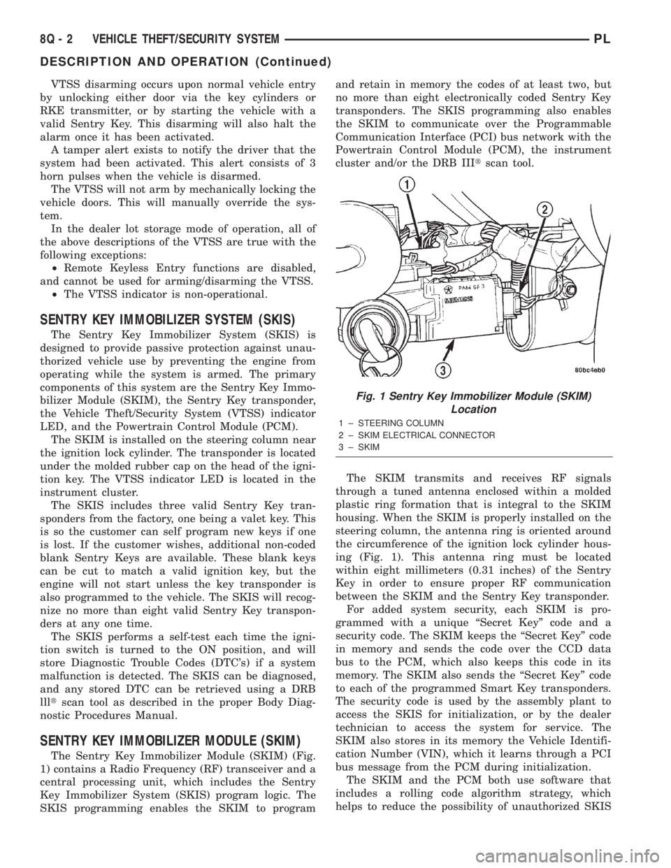
The SKIM is installed on the steering column near
the ignition lock cylinder. The transponder is located
under the molded rubber cap on the head of the igni-
tion key. The VTSS indicator LED is located in the
instrument cluster.
The SKIS includes three valid Sentry Key tran-
sponders from the factory, one being a valet key. This
is so the customer can self program new keys if one
is lost. If the customer wishes, additional non-coded
blank Sentry Keys are available. These blank keys
can be cut to match a valid ignition key, but the
engine will not start unless the key transponder is
also programmed to the vehicle. The SKIS will recog-
nize no more than eight valid Sentry Key transpon-
ders at any one time.
The SKIS performs a self-test each time the igni-
tion switch is turned to the ON position, and will
store Diagnostic Trouble Codes (DTC's) if a system
malfunction is detected. The SKIS can be diagnosed,
and any stored DTC can be retrieved using a DRB
llltscan tool as described in the proper Body Diag-
nostic Procedures Manual.
SENTRY KEY IMMOBILIZER MODULE (SKIM)
The Sentry Key Immobilizer Module (SKIM) (Fig.
1) contains a Radio Frequency (RF) transceiver and a
central processing unit, which includes the Sentry
Key Immobilizer System (SKIS) program logic. The
SKIS programming enables the SKIM to programand retain in memory the codes of at least two, but
no more than eight electronically coded Sentry Key
transponders. The SKIS programming also enables
the SKIM to communicate over the Programmable
Communication Interface (PCI) bus network with the
Powertrain Control Module (PCM), the instrument
cluster and/or the DRB IIItscan tool.
The SKIM transmits and receives RF signals
through a tuned antenna enclosed within a molded
plastic ring formation that is integral to the SKIM
housing. When the SKIM is properly installed on the
steering column, the antenna ring is oriented around
the circumference of the ignition lock cylinder hous-
ing (Fig. 1). This antenna ring must be located
within eight millimeters (0.31 inches) of the Sentry
Key in order to ensure proper RF communication
between the SKIM and the Sentry Key transponder.
For added system security, each SKIM is pro-
grammed with a unique ªSecret Keyº code and a
security code. The SKIM keeps the ªSecret Keyº code
in memory and sends the code over the CCD data
bus to the PCM, which also keeps this code in its
memory. The SKIM also sends the ªSecret Keyº code
to each of the programmed Smart Key transponders.
The security code is used by the assembly plant to
access the SKIS for initialization, or by the dealer
technician to access the system for service. The
SKIM also stores in its memory the Vehicle Identifi-
cation Number (VIN), which it learns through a PCI
bus message from the PCM during initialization.
The SKIM and the PCM both use software that
includes a rolling code algorithm strategy, which
helps to reduce the possibility of unauthorized SKIS
Fig. 1 Sentry Key Immobilizer Module (SKIM)
Location
1 ± STEERING COLUMN
2 ± SKIM ELECTRICAL CONNECTOR
3 ± SKIM
8Q - 2 VEHICLE THEFT/SECURITY SYSTEMPL
DESCRIPTION AND OPERATION (Continued)
Page 382 of 1285
POWER MIRRORS
TABLE OF CONTENTS
page page
DESCRIPTION AND OPERATION
INTRODUCTION..........................1
DIAGNOSIS AND TESTING
MIRROR SWITCH TEST....................1
POWER MIRROR MOTOR..................2
REMOVAL AND INSTALLATION
INSIDE MIRROR/READING LAMPS
ASSEMBLY.............................2INSIDE MIRROR/READING LAMPS
BULB/LENS............................3
MIRROR SWITCH.........................3
POWER MIRROR ASSEMBLY................3
DESCRIPTION AND OPERATION
INTRODUCTION
Electrically operated power mirrors are available
on all car lines. The mirrors are controlled by a sin-
gle switch assembly located on the driver's door trim
panel. The push button rocker switch uses L (left)
and R (right) for mirror selection and a button to
push for the desired direction of mirror movement.
The motors which operate the mirrors are part of
the mirror assembly and cannot be replaced sepa-
rately.
The Ignition Off Draw fuse is included in the
power mirror circuity and should be checked if the
mirrors are inoperative.
DIAGNOSIS AND TESTING
MIRROR SWITCH TEST
(1) Remove power mirror switch from mounting
position. Refer to Mirror Switch Removal and Instal-
lation in this section.
(2) Using an ohmmeter, test for continuity between
the terminals of the switch as shown in the Mirror
Switch Continuity table.
(3) If test results are not obtained as shown in the
Mirror Switch Continuity table, replace the switch.
Refer to Group 8W-Wiring Diagrams for Connector
Pin-Outs and Circuit Diagrams.
PLPOWER MIRRORS 8T - 1
Page 386 of 1285
POWER MIRRORS
TABLE OF CONTENTS
page page
GENERAL INFORMATION
INTRODUCTION..........................1
DIAGNOSIS AND TESTING
POWER FOLD AWAY MIRROR SWITCH TEST...1POWER FOLD AWAY MIRROR MOTOR........1
REMOVAL AND INSTALLATION
POWER FOLD-AWAY MIRROR SWITCH.......1
POWER FOLD-AWAY MIRROR...............2
GENERAL INFORMATION
INTRODUCTION
These vehicles may be equipped with Power Fold
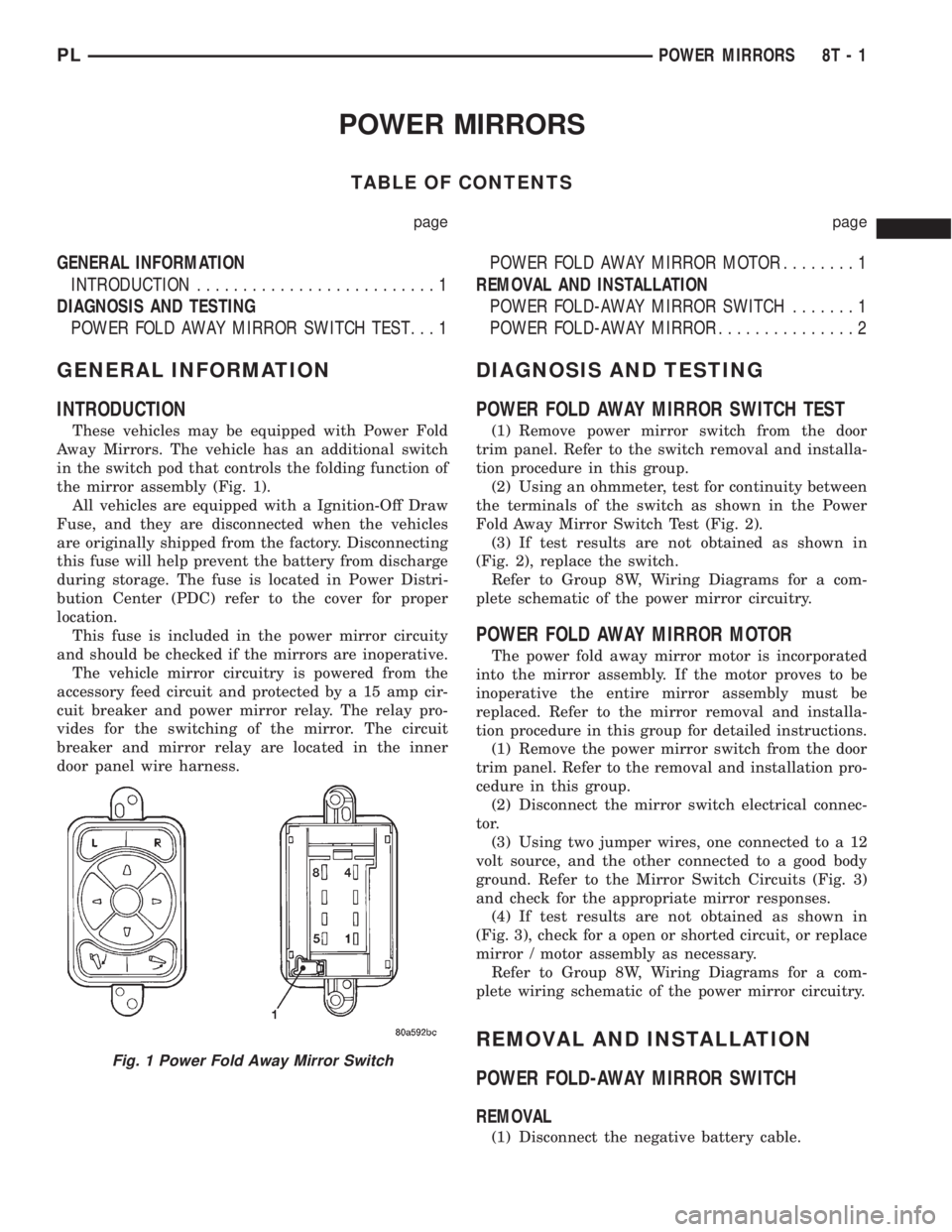
Away Mirrors. The vehicle has an additional switch
in the switch pod that controls the folding function of
the mirror assembly (Fig. 1).
All vehicles are equipped with a Ignition-Off Draw
Fuse, and they are disconnected when the vehicles
are originally shipped from the factory. Disconnecting
this fuse will help prevent the battery from discharge
during storage. The fuse is located in Power Distri-
bution Center (PDC) refer to the cover for proper
location.
This fuse is included in the power mirror circuity
and should be checked if the mirrors are inoperative.
The vehicle mirror circuitry is powered from the
accessory feed circuit and protected by a 15 amp cir-
cuit breaker and power mirror relay. The relay pro-
vides for the switching of the mirror. The circuit
breaker and mirror relay are located in the inner
door panel wire harness.
DIAGNOSIS AND TESTING
POWER FOLD AWAY MIRROR SWITCH TEST
(1) Remove power mirror switch from the door
trim panel. Refer to the switch removal and installa-
tion procedure in this group.
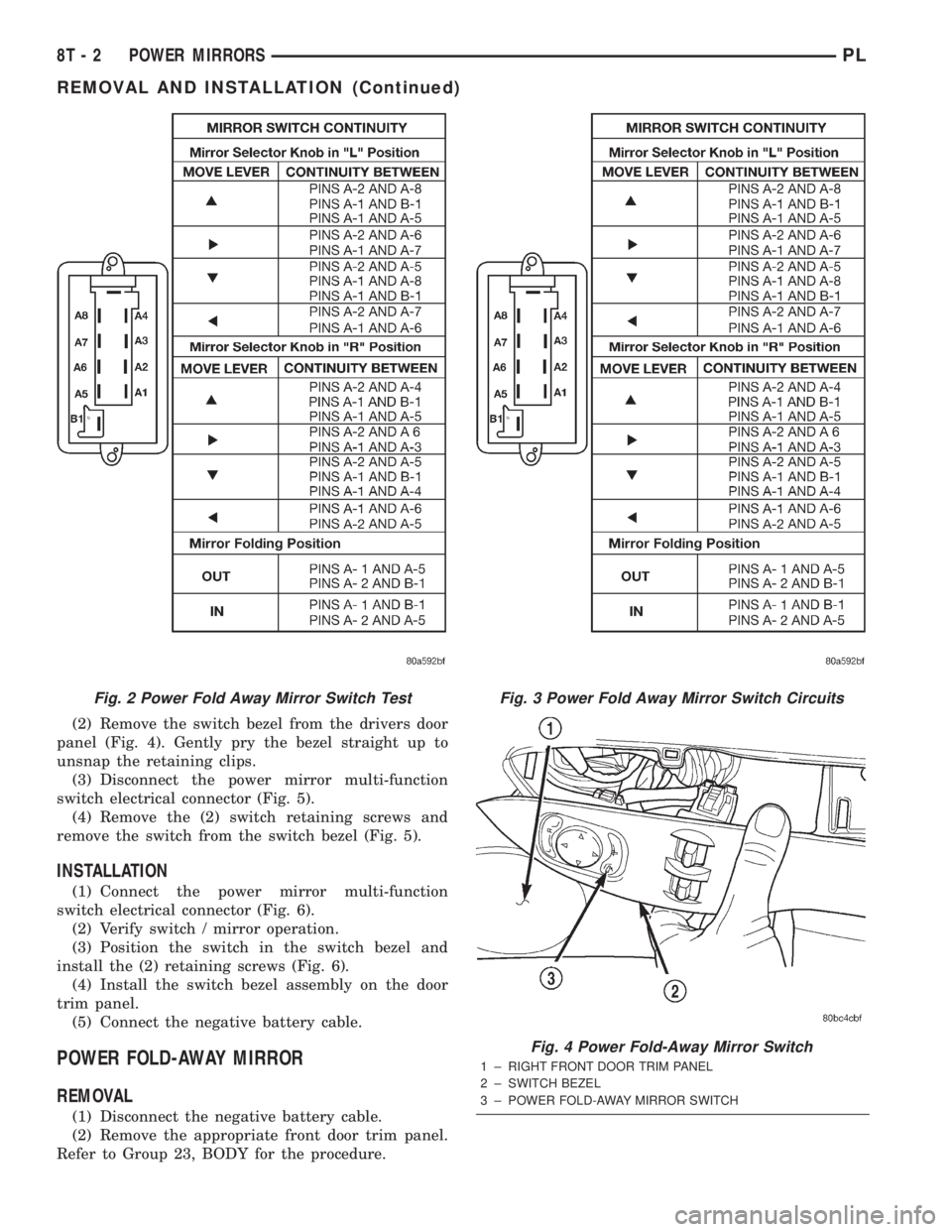
(2) Using an ohmmeter, test for continuity between
the terminals of the switch as shown in the Power
Fold Away Mirror Switch Test (Fig. 2).
(3) If test results are not obtained as shown in
(Fig. 2), replace the switch.
Refer to Group 8W, Wiring Diagrams for a com-
plete schematic of the power mirror circuitry.
POWER FOLD AWAY MIRROR MOTOR
The power fold away mirror motor is incorporated
into the mirror assembly. If the motor proves to be
inoperative the entire mirror assembly must be
replaced. Refer to the mirror removal and installa-
tion procedure in this group for detailed instructions.
(1) Remove the power mirror switch from the door
trim panel. Refer to the removal and installation pro-
cedure in this group.
(2) Disconnect the mirror switch electrical connec-
tor.
(3) Using two jumper wires, one connected to a 12
volt source, and the other connected to a good body
ground. Refer to the Mirror Switch Circuits (Fig. 3)
and check for the appropriate mirror responses.
(4) If test results are not obtained as shown in
(Fig. 3), check for a open or shorted circuit, or replace
mirror / motor assembly as necessary.
Refer to Group 8W, Wiring Diagrams for a com-
plete wiring schematic of the power mirror circuitry.
REMOVAL AND INSTALLATION
POWER FOLD-AWAY MIRROR SWITCH
REMOVAL
(1) Disconnect the negative battery cable.
Fig. 1 Power Fold Away Mirror Switch
PLPOWER MIRRORS 8T - 1
Page 387 of 1285
(2) Remove the switch bezel from the drivers door
panel (Fig. 4). Gently pry the bezel straight up to
unsnap the retaining clips.
(3) Disconnect the power mirror multi-function
switch electrical connector (Fig. 5).
(4) Remove the (2) switch retaining screws and
remove the switch from the switch bezel (Fig. 5).
INSTALLATION
(1) Connect the power mirror multi-function
switch electrical connector (Fig. 6).
(2) Verify switch / mirror operation.
(3) Position the switch in the switch bezel and
install the (2) retaining screws (Fig. 6).
(4) Install the switch bezel assembly on the door
trim panel.
(5) Connect the negative battery cable.
POWER FOLD-AWAY MIRROR
REMOVAL
(1) Disconnect the negative battery cable.
(2) Remove the appropriate front door trim panel.
Refer to Group 23, BODY for the procedure.
Fig. 2 Power Fold Away Mirror Switch TestFig. 3 Power Fold Away Mirror Switch Circuits
Fig. 4 Power Fold-Away Mirror Switch
1 ± RIGHT FRONT DOOR TRIM PANEL
2 ± SWITCH BEZEL
3 ± POWER FOLD-AWAY MIRROR SWITCH
8T - 2 POWER MIRRORSPL
REMOVAL AND INSTALLATION (Continued)
Page 388 of 1285
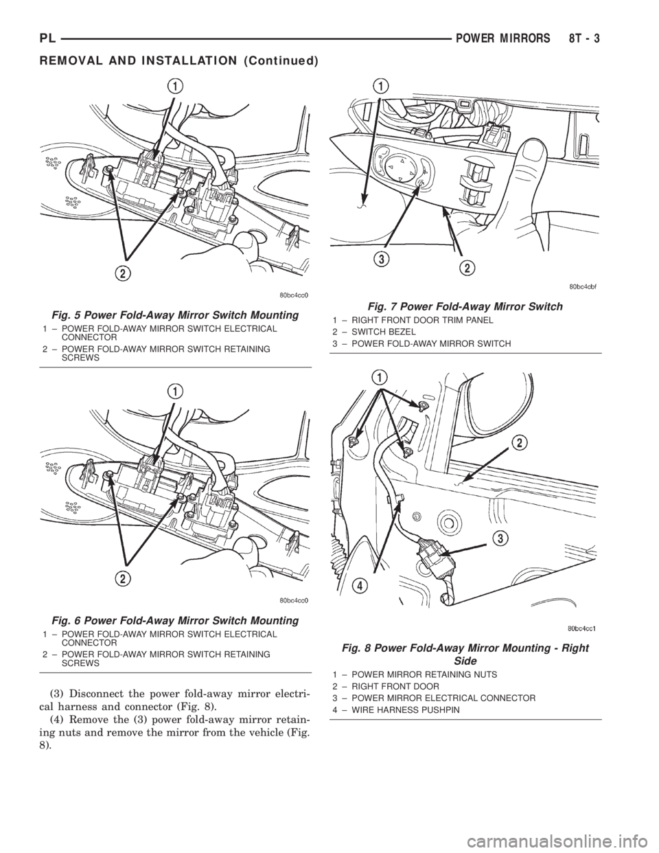
(3) Disconnect the power fold-away mirror electri-
cal harness and connector (Fig. 8).
(4) Remove the (3) power fold-away mirror retain-
ing nuts and remove the mirror from the vehicle (Fig.
8).
Fig. 5 Power Fold-Away Mirror Switch Mounting
1 ± POWER FOLD-AWAY MIRROR SWITCH ELECTRICAL
CONNECTOR
2 ± POWER FOLD-AWAY MIRROR SWITCH RETAINING
SCREWS
Fig. 6 Power Fold-Away Mirror Switch Mounting
1 ± POWER FOLD-AWAY MIRROR SWITCH ELECTRICAL
CONNECTOR
2 ± POWER FOLD-AWAY MIRROR SWITCH RETAINING
SCREWS
Fig. 7 Power Fold-Away Mirror Switch
1 ± RIGHT FRONT DOOR TRIM PANEL
2 ± SWITCH BEZEL
3 ± POWER FOLD-AWAY MIRROR SWITCH
Fig. 8 Power Fold-Away Mirror Mounting - Right
Side
1 ± POWER MIRROR RETAINING NUTS
2 ± RIGHT FRONT DOOR
3 ± POWER MIRROR ELECTRICAL CONNECTOR
4 ± WIRE HARNESS PUSHPIN
PLPOWER MIRRORS 8T - 3
REMOVAL AND INSTALLATION (Continued)
Page 389 of 1285
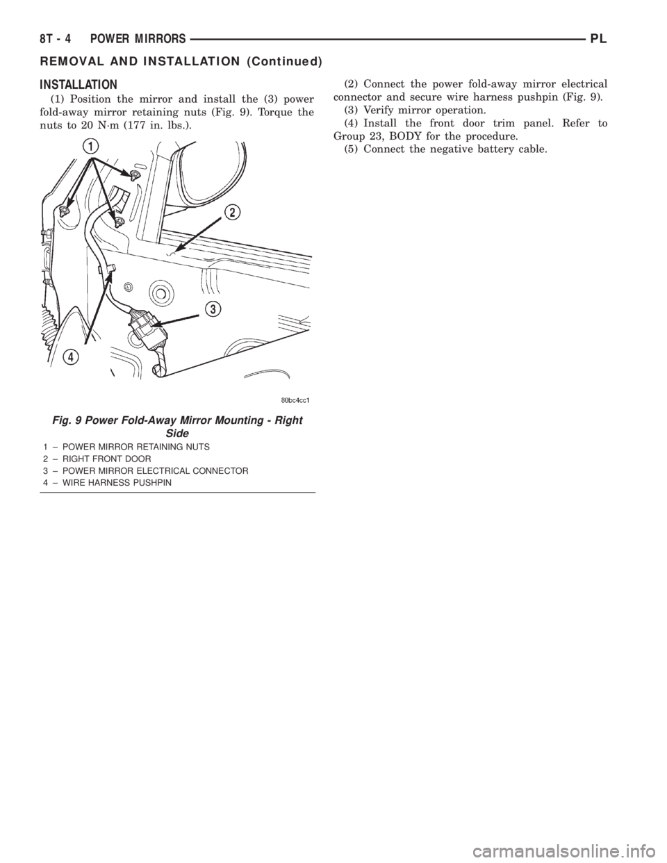
INSTALLATION
(1) Position the mirror and install the (3) power
fold-away mirror retaining nuts (Fig. 9). Torque the
nuts to 20 N´m (177 in. lbs.).(2) Connect the power fold-away mirror electrical
connector and secure wire harness pushpin (Fig. 9).
(3) Verify mirror operation.
(4) Install the front door trim panel. Refer to
Group 23, BODY for the procedure.
(5) Connect the negative battery cable.
Fig. 9 Power Fold-Away Mirror Mounting - Right
Side
1 ± POWER MIRROR RETAINING NUTS
2 ± RIGHT FRONT DOOR
3 ± POWER MIRROR ELECTRICAL CONNECTOR
4 ± WIRE HARNESS PUSHPIN
8T - 4 POWER MIRRORSPL
REMOVAL AND INSTALLATION (Continued)
Page 398 of 1285
SECTION IDENTIFICATION
The wiring diagrams are grouped into individual
sections. If a component is most likely found in a par-
ticular group, it will be shown complete (all wires,
connectors, and pins) within that group. For exam-
ple, the Auto Shutdown Relay is most likely to be
found in Group 30, so it is shown there complete. It
can, however, be shown partially in another group if
it contains some associated wiring.
SYMBOLS
International symbols are used throughout the wir-
ing diagrams. These symbols are consistent with
those being used around the world.
GROUP TOPIC
8W-01 thru
8W-09General Information and Diagram
Overview
8W-10 thru
8W-19Main Sources of Power and Vehicle
Grounding
8W-20 thru
8W-29Starting and Charging
8W-30 thru
8W-39Powertrain/Drivetrain Systems
8W-40 thru
8W-49Body Electrical items and A/C
8W-50 thru
8W-59Exterior Lighting, Wipers, and Trailer
To w
8W-60 thru
8W-69Power Accessories
8W-70 Splice Information
8W-80 Connector Pin Outs
8W-90 Connector Locations (including
grounds)
8W-95 Splice Locations
PL8W - 01 GENERAL INFORMATION 8W - 01 - 5
DESCRIPTION AND OPERATION (Continued)