2000 DODGE NEON electrical
[x] Cancel search: electricalPage 833 of 1285

REMOVAL AND INSTALLATION
AUTOMATIC SHUTDOWN RELAY
The relay is located in the Power Distribution Cen-
ter (PDC) (Fig. 12). The PDC is located next to the
battery in the engine compartment. For the location
of the relay within the PDC, refer to the PDC cover
for location. Check electrical terminals for corrosion
and repair as necessary.
FUEL PUMP RELAY
The fuel pump relay is located in the PDC. The
inside top of the PDC cover has a label showing relay
and fuse location.
FUEL PUMP MODULE
REMOVAL
WARNING: RELEASE FUEL SYSTEM PRESSURE
BEFORE SERVICING FUEL SYSTEM COMPONENTS.
SERVICE VEHICLES IN WELL VENTILATED AREAS
AND AVOID IGNITION SOURCES. NEVER SMOKE
WHILE SERVICING THE VEHICLE.
(1) Drain the fuel. Refer to Draining Fuel Tank in
the Fuel Tank section of this group.
WARNING: THE FUEL RESERVOIR OF THE FUEL
PUMP MODULE DOES NOT EMPTY OUT WHEN THE
TANK IS DRAINED. THE FUEL IN THE RESERVOIR
WILL SPILL OUT WHEN THE MODULE IS
REMOVED.
(2) Remove fuel tank, refer to the Fuel Tank
removal/installation section.
(3) Lower tank.(4) Use Special Tool 6856 to remove fuel pump
module locknut (Fig. 15).
(5) Remove fuel pump and O-ring seal from tank.
Discard old seal.
INSTALLATION
(1) Wipe seal area of tank clean and place a new
seal in position in the tank opening.
(2) Position fuel pump in the tank. Make sure the
alignment tab on the underside of the fuel pump
module flange sits in the notch on the fuel tank (Fig.
14).
(3) Position the locknut over the fuel pump mod-
ule.
Fig. 12 Power Distribution Center (PDC)
Fig. 13 Fuel Pump Module Removal
1 ± FUEL FILTER/PRESSURE REGULATOR
2 ± FUEL LINE
3 ± LOCKNUT
Fig. 14 Alignment Tab
14 - 12 FUEL SYSTEMPL
Page 835 of 1285
FUEL PUMP INLET STRAINER
REMOVAL
(1) Remove fuel pump module. Refer to Fuel Pump
Module Removal in this section.
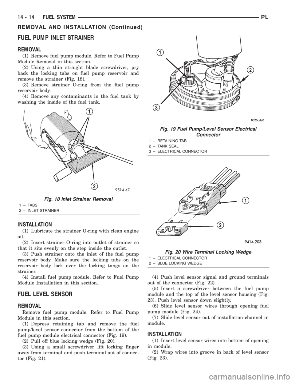
(2) Using a thin straight blade screwdriver, pry
back the locking tabs on fuel pump reservoir and
remove the strainer (Fig. 18).
(3) Remove strainer O-ring from the fuel pump
reservoir body.
(4) Remove any contaminants in the fuel tank by
washing the inside of the fuel tank.
INSTALLATION
(1) Lubricate the strainer O-ring with clean engine
oil.
(2) Insert strainer O-ring into outlet of strainer so
that it sits evenly on the step inside the outlet.
(3) Push strainer onto the inlet of the fuel pump
reservoir body. Make sure the locking tabs on the
reservoir body lock over the locking tangs on the
strainer.
(4) Install fuel pump module. Refer to Fuel Pump
Module Installation in this section.
FUEL LEVEL SENSOR
REMOVAL
Remove fuel pump module. Refer to Fuel Pump
Module in this section.
(1) Depress retaining tab and remove the fuel
pump/level sensor connector from the bottom of the
fuel pump module electrical connector (Fig. 19).
(2) Pull off blue locking wedge (Fig. 20).
(3) Using a small screwdriver lift locking finger
away from terminal and push terminal out of connec-
tor (Fig. 21).(4) Push level sensor signal and ground terminals
out of the connector (Fig. 22).
(5) Insert a screwdriver between the fuel pump
module and the top of the level sensor housing (Fig.
23). Push level sensor down slightly.
(6) Slide level sensor wires through opening fuel
pump module (Fig. 24).
(7) Slide level sensor out of installation channel in
module.
INSTALLATION
(1) Insert level sensor wires into bottom of opening
in module.
(2) Wrap wires into groove in back of level sensor
(Fig. 23).
Fig. 18 Inlet Strainer Removal
1±TABS
2 ± INLET STRAINER
Fig. 19 Fuel Pump/Level Sensor Electrical
Connector
1 ± RETAINING TAB
2 ± TANK SEAL
3 ± ELECTRICAL CONNECTOR
Fig. 20 Wire Terminal Locking Wedge
1 ± ELECTRICAL CONNECTOR
2 ± BLUE LOCKING WEDGE
14 - 14 FUEL SYSTEMPL
REMOVAL AND INSTALLATION (Continued)
Page 836 of 1285
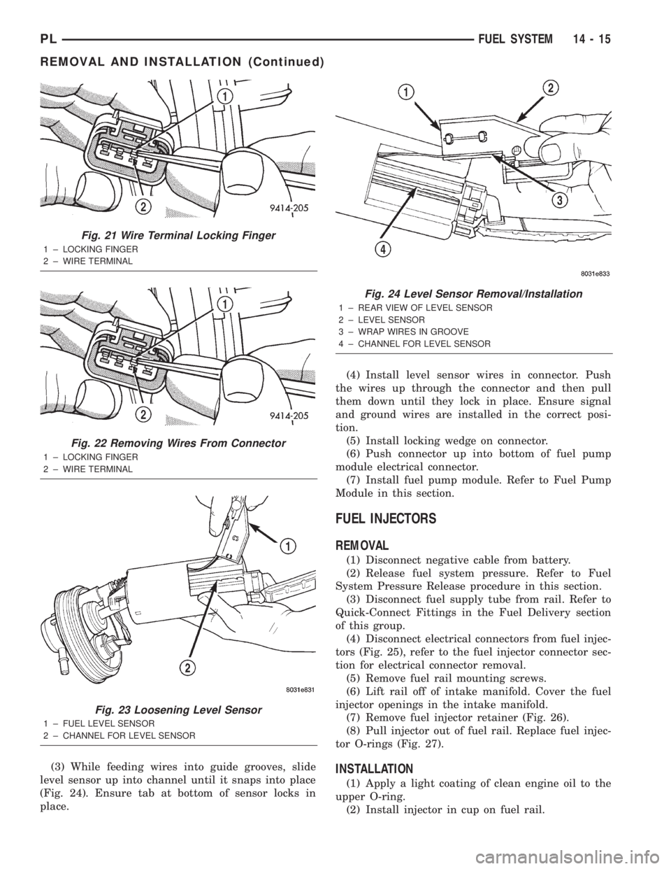
(3) While feeding wires into guide grooves, slide
level sensor up into channel until it snaps into place
(Fig. 24). Ensure tab at bottom of sensor locks in
place.(4) Install level sensor wires in connector. Push
the wires up through the connector and then pull
them down until they lock in place. Ensure signal
and ground wires are installed in the correct posi-
tion.
(5) Install locking wedge on connector.
(6) Push connector up into bottom of fuel pump
module electrical connector.
(7) Install fuel pump module. Refer to Fuel Pump
Module in this section.
FUEL INJECTORS
REMOVAL
(1) Disconnect negative cable from battery.
(2) Release fuel system pressure. Refer to Fuel
System Pressure Release procedure in this section.
(3) Disconnect fuel supply tube from rail. Refer to
Quick-Connect Fittings in the Fuel Delivery section
of this group.
(4) Disconnect electrical connectors from fuel injec-
tors (Fig. 25), refer to the fuel injector connector sec-
tion for electrical connector removal.
(5) Remove fuel rail mounting screws.
(6) Lift rail off of intake manifold. Cover the fuel
injector openings in the intake manifold.
(7) Remove fuel injector retainer (Fig. 26).
(8) Pull injector out of fuel rail. Replace fuel injec-
tor O-rings (Fig. 27).
INSTALLATION
(1) Apply a light coating of clean engine oil to the
upper O-ring.
(2) Install injector in cup on fuel rail.
Fig. 21 Wire Terminal Locking Finger
1 ± LOCKING FINGER
2 ± WIRE TERMINAL
Fig. 22 Removing Wires From Connector
1 ± LOCKING FINGER
2 ± WIRE TERMINAL
Fig. 23 Loosening Level Sensor
1 ± FUEL LEVEL SENSOR
2 ± CHANNEL FOR LEVEL SENSOR
Fig. 24 Level Sensor Removal/Installation
1 ± REAR VIEW OF LEVEL SENSOR
2 ± LEVEL SENSOR
3 ± WRAP WIRES IN GROOVE
4 ± CHANNEL FOR LEVEL SENSOR
PLFUEL SYSTEM 14 - 15
REMOVAL AND INSTALLATION (Continued)
Page 837 of 1285

(3) Install retaining clip.
(4) Apply a light coating of clean engine oil to the
O-ring on the nozzle end of each injector.
(5) Insert fuel injector nozzles into openings in
intake manifold. Seat the injectors in place. Tighten
fuel rail mounting screws to 22.5 N´m63 N´m
(200630 in. lbs.).
(6) Attach electrical connectors to fuel injectors,
refer to the fuel injector connector section for electri-
cal connector installation.
(7) Connect fuel supply tube to fuel rail. Refer to
Quick Connect Fittings in the Fuel Delivery Section
of this Group.
FUEL TANK
REMOVAL
(1) Disconnect the negative battery cable (Fig. 28).
(2) Perform fuel system pressure release, refer to
the fuel system pressure release procedure in this
section.
(3) Raise and support vehicle on hoist.
(4) Disconnect vapor line from EVAP canister tube.
(5) Remove EVAP canister (Fig. 29).
(6) Drain fuel tank. Remove the drain port cap and
remove fuel. Drain fuel tank into holding tank or a
properly labeledGasolinesafety container. Reinstall
drain port cap when done draining fuel (Fig. 30).
Fig. 25 Fuel Rail and Injectors
1 ± FUEL SUPPLY LINE
2 ± FUEL LINE QUICK-CONNECTS
3 ± IGNITION COIL
4 ± FUEL RAIL
5 ± FUEL INJECTOR
Fig. 26 Fuel Injector Retainer
1 ± RETAINER
2 ± FUEL RAIL
3 ± FUEL INJECTOR
Fig. 27 Fuel Injector O-Rings
1 ± FUEL INJECTOR
2 ± NOZZLE
3 ± TOP (FUEL ENTRY)
Fig. 28 Battery Cable
14 - 16 FUEL SYSTEMPL
REMOVAL AND INSTALLATION (Continued)
Page 838 of 1285

(7) Disconnect fuel pump module electrical connec-
tor and ground wire (Fig. 31).
(8) Disconnect the fuel tube from Fuel Filter/Reg-
ulator. Refer to Quick Connect Fittings in the Fuel
Delivery section of this group.
(9) Disconnect fuel filler tube and filler vent tube
from filler hose at fuel tank.
(10) Support tank with transmission jack. Loosen
tank mounting straps and lower tank slightly.
(11) Remove tank mounting straps and lower tank.
INSTALLATION
(1) Position fuel tank on transmission jack.
(2) Raise tank into position.
(3) Tighten fuel tank strap nuts to 22.5 N´m (200
in. lbs.) torque. Remove transmission jack. Ensure
straps are not twisted or bent.(4) Connect fuel filler tube tank inlet nipple.
Tighten clamp.
(5) Connect EVAP vent hose.
(6) Attach fuel tubes to pump module and chassis
fuel tube. Refer to Quick Connect Fittings in the Fuel
Delivery section of this Group.
(7) Attach electrical connector and ground wire to
fuel pump module.
(8) Install vapor lines to EVAP canister.
(9) Install EVAP canister.
(10) Lower vehicle.
(11) Fill fuel tank, install filler cap, and connect
battery cable.
CAUTION: When using the ASD Fuel System Test,
the Auto Shutdown (ASD) Relay remains energized
for either 7 minutes, until the test is stopped, or
until the ignition switch is turned to the Off posi-
tion.
(12) Use the DRB scan tool ASD Fuel System Test
to pressurize the fuel system. Check for leaks.
FUEL FILLER NECK
REMOVAL
(1) Loosen fuel filler tube cap.
(2) Remove fuel filler neck screws (Fig. 32).
(3) Raise and support vehicle.
(4) Remove splash shield from wheel well.
(5) Disconnect fuel fill vapor tube.
(6) Disconnect fuel filler tube from fuel tank.
(7) Remove groundstrap from body.
(8) Remove filler neck (Fig. 33).
Fig. 29 EVAP Canister
Fig. 30 Fuel Tank
Fig. 31 Pump Module Electrical Connector
1 ± ELECTRICAL CONNECTOR
2 ± FUEL LINE
PLFUEL SYSTEM 14 - 17
REMOVAL AND INSTALLATION (Continued)
Page 843 of 1285
DESCRIPTION AND OPERATION
INJECTION SYSTEM
All engines used in this section have a sequential
Multi-Port Electronic Fuel Injection system. The MPI
system is computer regulated and provides precise
air/fuel ratios for all driving conditions. The Power-
train Control Module (PCM) operates the fuel injec-
tion system.
The PCM regulates:
²Ignition timing
²Air/fuel ratio
²Emission control devices
²Cooling fan
²Charging system
²Idle speed
²Vehicle speed control
Various sensors provide the inputs necessary for
the PCM to correctly operate these systems. In addi-
tion to the sensors, various switches also provide
inputs to the PCM.
All inputs to the PCM are converted into signals.
The PCM can adapt its programming to meet chang-
ing operating conditions.
Fuel is injected into the intake port above the
intake valve in precise metered amounts through
electrically operated injectors. The PCM fires the
injectors in a specific sequence. Under most operat-
ing conditions, the PCM maintains an air fuel ratio
of 14.7 parts air to 1 part fuel by constantly adjust-
ing injector pulse width. Injector pulse width is the
length of time the injector is open.
The PCM adjusts injector pulse width by opening
and closing the ground path to the injector. Engine
RPM (speed) and manifold absolute pressure (air
density) are the primary inputs that determine injec-
tor pulse width.
MODES OF OPERATION
OPERATION
As input signals to the PCM change, the PCM
adjusts its response to output devices. For example,
the PCM must calculate a different injector pulse
width and ignition timing for idle than it does for
Wide Open Throttle (WOT). There are several differ-
ent modes of operation that determine how the PCM
responds to the various input signals.
There are two different areas of operation, OPEN
LOOP and CLOSED LOOP.
During OPEN LOOP modes the PCM receives
input signals and responds according to preset PCM
programming. Inputs from the upstream and down-
stream heated oxygen sensors are not monitored dur-
ing OPEN LOOP modes, except for heated oxygensensor diagnostics (they are checked for shorted con-
ditions at all times).
During CLOSED LOOP modes the PCM monitors
the inputs from the upstream and downstream
heated oxygen sensors. The upstream heated oxygen
sensor input tells the PCM if the calculated injector
pulse width resulted in the ideal air-fuel ratio of 14.7
to one. By monitoring the exhaust oxygen content
through the upstream heated oxygen sensor, the
PCM can fine tune injector pulse width. Fine tuning
injector pulse width allows the PCM to achieve opti-
mum fuel economy combined with low emissions.
For the PCM to enter CLOSED LOOP operation,
the following must occur:
(1) Engine coolant temperature must be over 35ÉF.
²If the coolant is over 35É the PCM will wait 44
seconds.
²If the coolant is over 50ÉF the PCM will wait 38
seconds.
²If the coolant is over 167ÉF the PCM will wait
11 seconds.
(2) For other temperatures the PCM will interpo-
late the correct waiting time.
(3) O2 sensor must read either greater than 0.745
volts or less than 0.1 volt.
(4) The multi-port fuel injection systems has the
following modes of operation:
²Ignition switch ON (Zero RPM)
²Engine start-up
²Engine warm-up
²Cruise
²Idle
²Acceleration
²Deceleration
²Wide Open Throttle
²Ignition switch OFF
(5) The engine start-up (crank), engine warm-up,
deceleration with fuel shutoff and wide open throttle
modes are OPEN LOOP modes. Under most operat-
ing conditions, the acceleration, deceleration (with
A/C on), idle and cruise modes,with the engine at
operating temperatureare CLOSED LOOP modes.
IGNITION SWITCH ON (ZERO RPM) MODE
When the ignition switch activates the fuel injec-
tion system, the following actions occur:
²The PCM monitors the engine coolant tempera-
ture sensor and throttle position sensor input. The
PCM determines basic fuel injector pulse width from
this input.
²The PCM determines atmospheric air pressure
from the MAP sensor input to modify injector pulse
width.
When the key is in the ON position and the engine
is not running (zero rpm), the Auto Shutdown (ASD)
and fuel pump relays de-energize after approximately
14 - 22 FUEL SYSTEMPL
Page 853 of 1285
HEATED OXYGEN SENSOR (O2 SENSOR)Ð
PCM INPUT
DESCRIPTION
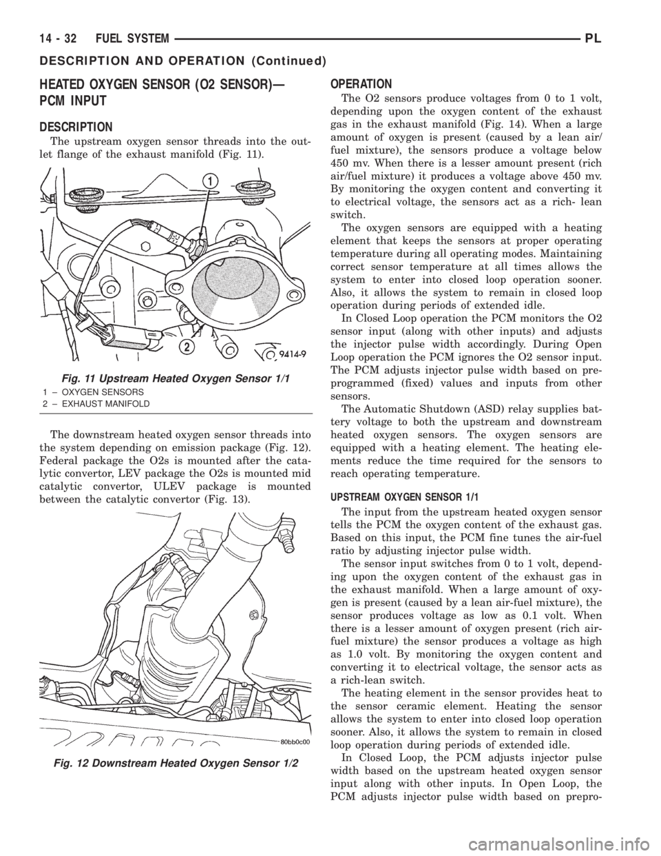
The upstream oxygen sensor threads into the out-
let flange of the exhaust manifold (Fig. 11).
The downstream heated oxygen sensor threads into
the system depending on emission package (Fig. 12).
Federal package the O2s is mounted after the cata-
lytic convertor, LEV package the O2s is mounted mid
catalytic convertor, ULEV package is mounted
between the catalytic convertor (Fig. 13).
OPERATION
The O2 sensors produce voltages from 0 to 1 volt,
depending upon the oxygen content of the exhaust
gas in the exhaust manifold (Fig. 14). When a large
amount of oxygen is present (caused by a lean air/
fuel mixture), the sensors produce a voltage below
450 mv. When there is a lesser amount present (rich
air/fuel mixture) it produces a voltage above 450 mv.
By monitoring the oxygen content and converting it
to electrical voltage, the sensors act as a rich- lean
switch.
The oxygen sensors are equipped with a heating
element that keeps the sensors at proper operating
temperature during all operating modes. Maintaining
correct sensor temperature at all times allows the
system to enter into closed loop operation sooner.
Also, it allows the system to remain in closed loop
operation during periods of extended idle.
In Closed Loop operation the PCM monitors the O2
sensor input (along with other inputs) and adjusts
the injector pulse width accordingly. During Open
Loop operation the PCM ignores the O2 sensor input.
The PCM adjusts injector pulse width based on pre-
programmed (fixed) values and inputs from other
sensors.
The Automatic Shutdown (ASD) relay supplies bat-
tery voltage to both the upstream and downstream
heated oxygen sensors. The oxygen sensors are
equipped with a heating element. The heating ele-
ments reduce the time required for the sensors to
reach operating temperature.
UPSTREAM OXYGEN SENSOR 1/1
The input from the upstream heated oxygen sensor
tells the PCM the oxygen content of the exhaust gas.
Based on this input, the PCM fine tunes the air-fuel
ratio by adjusting injector pulse width.
The sensor input switches from 0 to 1 volt, depend-
ing upon the oxygen content of the exhaust gas in
the exhaust manifold. When a large amount of oxy-
gen is present (caused by a lean air-fuel mixture), the
sensor produces voltage as low as 0.1 volt. When
there is a lesser amount of oxygen present (rich air-
fuel mixture) the sensor produces a voltage as high
as 1.0 volt. By monitoring the oxygen content and
converting it to electrical voltage, the sensor acts as
a rich-lean switch.
The heating element in the sensor provides heat to
the sensor ceramic element. Heating the sensor
allows the system to enter into closed loop operation
sooner. Also, it allows the system to remain in closed
loop operation during periods of extended idle.
In Closed Loop, the PCM adjusts injector pulse
width based on the upstream heated oxygen sensor
input along with other inputs. In Open Loop, the
PCM adjusts injector pulse width based on prepro-
Fig. 11 Upstream Heated Oxygen Sensor 1/1
1 ± OXYGEN SENSORS
2 ± EXHAUST MANIFOLD
Fig. 12 Downstream Heated Oxygen Sensor 1/2
14 - 32 FUEL SYSTEMPL
DESCRIPTION AND OPERATION (Continued)
Page 856 of 1285
OPERATION
When the knock sensor detects a knock in one of
the cylinders, it sends an input signal to the PCM. In
response, the PCM retards ignition timing for all cyl-
inders by a scheduled amount.
Knock sensors contain a piezoelectric material
which sends an input voltage (signal) to the PCM. As
the intensity of the engine knock vibration increases,
the knock sensor output voltage also increases.
The voltage signal produced by the knock sensor
increases with the amplitude of vibration. The PCM
receives as an input the knock sensor voltage signal.
If the signal rises above a predetermined level, the
PCM will store that value in memory and retard
ignition timing to reduce engine knock. If the knock
sensor voltage exceeds a preset value, the PCM
retards ignition timing for all cylinders. It is not a
selective cylinder retard.
The PCM ignores knock sensor input during engine
idle conditions. Once the engine speed exceeds a
specified value, knock retard is allowed.
Knock retard uses its own short term and long
term memory program.
Long term memory stores previous detonation
information in its battery-backed RAM. The maxi-
mum authority that long term memory has over tim-
ing retard can be calibrated.
Short term memory is allowed to retard timing up
to a preset amount under all operating conditions (as
long as rpm is above the minimum rpm) except WOT.
The PCM, using short term memory, can respond
quickly to retard timing when engine knock is
detected. Short term memory is lost any time the
ignition key is turned off.
MANIFOLD ABSOLUTE PRESSURE (MAP)
SENSORÐPCM INPUT
DESCRIPTION
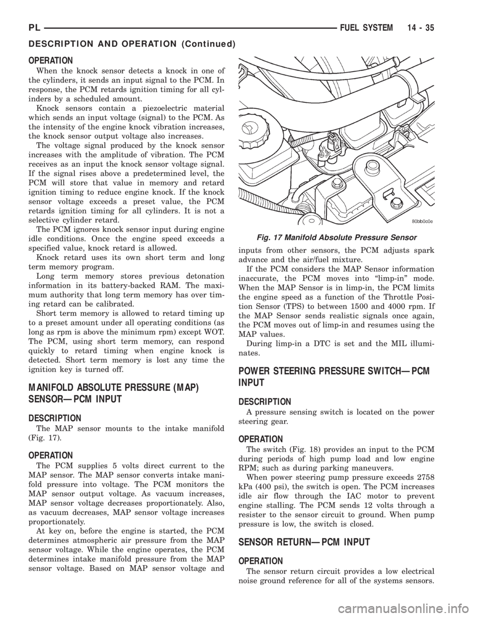
The MAP sensor mounts to the intake manifold
(Fig. 17).
OPERATION
The PCM supplies 5 volts direct current to the
MAP sensor. The MAP sensor converts intake mani-
fold pressure into voltage. The PCM monitors the
MAP sensor output voltage. As vacuum increases,
MAP sensor voltage decreases proportionately. Also,
as vacuum decreases, MAP sensor voltage increases
proportionately.
At key on, before the engine is started, the PCM
determines atmospheric air pressure from the MAP
sensor voltage. While the engine operates, the PCM
determines intake manifold pressure from the MAP
sensor voltage. Based on MAP sensor voltage andinputs from other sensors, the PCM adjusts spark
advance and the air/fuel mixture.
If the PCM considers the MAP Sensor information
inaccurate, the PCM moves into ªlimp-inº mode.
When the MAP Sensor is in limp-in, the PCM limits
the engine speed as a function of the Throttle Posi-
tion Sensor (TPS) to between 1500 and 4000 rpm. If
the MAP Sensor sends realistic signals once again,
the PCM moves out of limp-in and resumes using the
MAP values.
During limp-in a DTC is set and the MIL illumi-
nates.
POWER STEERING PRESSURE SWITCHÐPCM
INPUT
DESCRIPTION
A pressure sensing switch is located on the power
steering gear.
OPERATION
The switch (Fig. 18) provides an input to the PCM
during periods of high pump load and low engine
RPM; such as during parking maneuvers.
When power steering pump pressure exceeds 2758
kPa (400 psi), the switch is open. The PCM increases
idle air flow through the IAC motor to prevent
engine stalling. The PCM sends 12 volts through a
resister to the sensor circuit to ground. When pump
pressure is low, the switch is closed.
SENSOR RETURNÐPCM INPUT
OPERATION
The sensor return circuit provides a low electrical
noise ground reference for all of the systems sensors.
Fig. 17 Manifold Absolute Pressure Sensor
PLFUEL SYSTEM 14 - 35
DESCRIPTION AND OPERATION (Continued)