2000 DODGE NEON electrical
[x] Cancel search: electricalPage 1000 of 1285
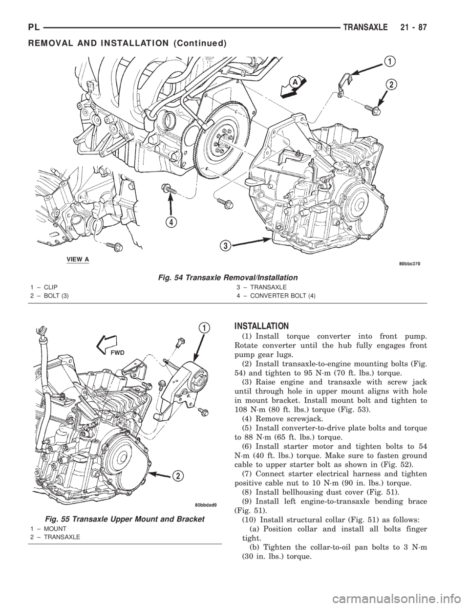
INSTALLATION
(1) Install torque converter into front pump.
Rotate converter until the hub fully engages front
pump gear lugs.
(2) Install transaxle-to-engine mounting bolts (Fig.
54) and tighten to 95 N´m (70 ft. lbs.) torque.
(3) Raise engine and transaxle with screw jack
until through hole in upper mount aligns with hole
in mount bracket. Install mount bolt and tighten to
108 N´m (80 ft. lbs.) torque (Fig. 53).
(4) Remove screwjack.
(5) Install converter-to-drive plate bolts and torque
to 88 N´m (65 ft. lbs.) torque.
(6) Install starter motor and tighten bolts to 54
N´m (40 ft. lbs.) torque. Make sure to fasten ground
cable to upper starter bolt as shown in (Fig. 52).
(7) Connect starter electrical harness and tighten
positive cable nut to 10 N´m (90 in. lbs.) torque.
(8) Install bellhousing dust cover (Fig. 51).
(9) Install left engine-to-transaxle bending brace
(Fig. 51).
(10) Install structural collar (Fig. 51) as follows:
(a) Position collar and install all bolts finger
tight.
(b) Tighten the collar-to-oil pan bolts to 3 N´m
(30 in. lbs.) torque.
Fig. 54 Transaxle Removal/Installation
1 ± CLIP
2 ± BOLT (3)3 ± TRANSAXLE
4 ± CONVERTER BOLT (4)
Fig. 55 Transaxle Upper Mount and Bracket
1 ± MOUNT
2 ± TRANSAXLE
PLTRANSAXLE 21 - 87
REMOVAL AND INSTALLATION (Continued)
Page 1098 of 1285
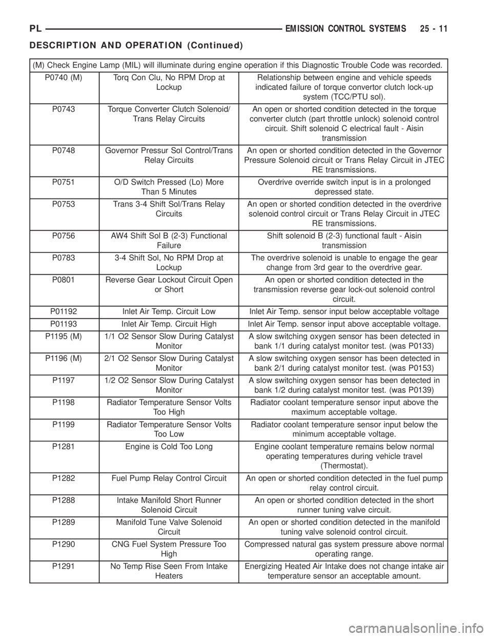
(M) Check Engine Lamp (MIL) will illuminate during engine operation if this Diagnostic Trouble Code was recorded.
P0740 (M) Torq Con Clu, No RPM Drop at
LockupRelationship between engine and vehicle speeds
indicated failure of torque convertor clutch lock-up
system (TCC/PTU sol).
P0743 Torque Converter Clutch Solenoid/
Trans Relay CircuitsAn open or shorted condition detected in the torque
converter clutch (part throttle unlock) solenoid control
circuit. Shift solenoid C electrical fault - Aisin
transmission
P0748 Governor Pressur Sol Control/Trans
Relay CircuitsAn open or shorted condition detected in the Governor
Pressure Solenoid circuit or Trans Relay Circuit in JTEC
RE transmissions.
P0751 O/D Switch Pressed (Lo) More
Than 5 MinutesOverdrive override switch input is in a prolonged
depressed state.
P0753 Trans 3-4 Shift Sol/Trans Relay
CircuitsAn open or shorted condition detected in the overdrive
solenoid control circuit or Trans Relay Circuit in JTEC
RE transmissions.
P0756 AW4 Shift Sol B (2-3) Functional
FailureShift solenoid B (2-3) functional fault - Aisin
transmission
P0783 3-4 Shift Sol, No RPM Drop at
LockupThe overdrive solenoid is unable to engage the gear
change from 3rd gear to the overdrive gear.
P0801 Reverse Gear Lockout Circuit Open
or ShortAn open or shorted condition detected in the
transmission reverse gear lock-out solenoid control
circuit.
P01192 Inlet Air Temp. Circuit Low Inlet Air Temp. sensor input below acceptable voltage
P01193 Inlet Air Temp. Circuit High Inlet Air Temp. sensor input above acceptable voltage.
P1195 (M) 1/1 O2 Sensor Slow During Catalyst
MonitorA slow switching oxygen sensor has been detected in
bank 1/1 during catalyst monitor test. (was P0133)
P1196 (M) 2/1 O2 Sensor Slow During Catalyst
MonitorA slow switching oxygen sensor has been detected in
bank 2/1 during catalyst monitor test. (was P0153)
P1197 1/2 O2 Sensor Slow During Catalyst
MonitorA slow switching oxygen sensor has been detected in
bank 1/2 during catalyst monitor test. (was P0139)
P1198 Radiator Temperature Sensor Volts
Too HighRadiator coolant temperature sensor input above the
maximum acceptable voltage.
P1199 Radiator Temperature Sensor Volts
Too LowRadiator coolant temperature sensor input below the
minimum acceptable voltage.
P1281 Engine is Cold Too Long Engine coolant temperature remains below normal
operating temperatures during vehicle travel
(Thermostat).
P1282 Fuel Pump Relay Control Circuit An open or shorted condition detected in the fuel pump
relay control circuit.
P1288 Intake Manifold Short Runner
Solenoid CircuitAn open or shorted condition detected in the short
runner tuning valve circuit.
P1289 Manifold Tune Valve Solenoid
CircuitAn open or shorted condition detected in the manifold
tuning valve solenoid control circuit.
P1290 CNG Fuel System Pressure Too
HighCompressed natural gas system pressure above normal
operating range.
P1291 No Temp Rise Seen From Intake
HeatersEnergizing Heated Air Intake does not change intake air
temperature sensor an acceptable amount.
PLEMISSION CONTROL SYSTEMS 25 - 11
DESCRIPTION AND OPERATION (Continued)
Page 1102 of 1285
MONITORED SYSTEMS
DESCRIPTION
There are new electronic circuit monitors that
check fuel, emission, engine and ignition perfor-
mance. These monitors use information from various
sensor circuits to indicate the overall operation of the
fuel, engine, ignition and emission systems and thus
the emissions performance of the vehicle.
The fuel, engine, ignition and emission systems
monitors do not indicate a specific component prob-
lem. They do indicate that there is an implied prob-
lem within one of the systems and that a specific
problem must be diagnosed.
If any of these monitors detect a problem affecting
vehicle emissions, the Malfunction Indicator (Check
Engine) Lamp will be illuminated. These monitors
generate Diagnostic Trouble Codes that can be dis-
played with the check engine lamp or a scan tool.
The following is a list of the monitored systems:
²EGR Monitor
²Misfire Monitor
²Fuel System Monitor
²Evaporative Emissions Monitor
Following is a description of each system monitor,
and its DTC.
Refer to the appropriate Powertrain Diagnos-
tics Procedures manual for diagnostic proce-
dures.
EGR MONITOR
The Powertrain Control Module (PCM) performs
an on-board diagnostic check of the EGR system.
The EGR system consists of two main components:
a vacuum solenoid back pressure transducer and a
vacuum operated valve. The EGR monitor is used to
test whether the EGR system is operating within
specifications. The diagnostic check activates only
during selected engine/driving conditions. When the
conditions are met, the EGR is turned off (solenoid
energized) and the O2S compensation control is mon-
itored. Turning off the EGR shifts the air fuel (A/F)
ratio in the lean direction. Oxygen sensor voltage
then indicates increased oxygen in the exhaust. Con-
sequently, Short Term Compensation shifts to rich
(increased injector pulse width). By monitoring the
shift, the PCM can indirectly monitor the EGR sys-
tem. While this test does not directly measure the
operation of the EGR system, it can be inferred from
the shift in the O2S data whether the EGR system is
operating correctly. Because the O2S is being used,
the O2S test must pass its test before the EGR test.
Enabling ConditionsÐ
²Engine Temperature
²Engine Run Time
²Engine RPM²MAP Sensor
²TPS
²Vehicle Speed
²Short Term Compensation
Pending ConditionsÐThe EGR Monitor does
not run when any of the following example faults
have illuminated the MIL:
²Misfire
²Oxygen Sensor Monitor
²Oxygen Sensor Heater Monitor
²Fuel System Rich/Lean
²Limp in for MAP, TPS or ECT
²Vehicle Speed Sensor
²Cam or Crank Sensor
²EGR Electrical
²EVAP Electrical
²Fuel Injector
²Ignition Coil
²Idle Speed
²Engine Coolant Temperature (ECT)
²MAP Sensor
²Intake Air Temperature (IAT)
Conflict ConditionsÐThe EGR Monitor typi-
cally does not run if any of the following conditions
are present:
²Fuel System Monitor
²Purge Monitor
²Catalyst Monitor
²Low Fuel Level
²High Altitude
²Low Ambient Air Temperature
The EGR Monitor does not run if any of the follow-
ing example DTCs are present:
²Misfire Monitor, Priority 2
²Upstream Oxygen Sensor Heater, Priority 1
²Fuel System Monitor, Priority 2
²Oxygen Sensor Monitor, Priority 1
MISFIRE MONITOR
Excessive engine misfire results in increased cata-
lyst temperature and causes an increase in HC emis-
sions. Severe misfires could cause catalyst damage.
To prevent catalytic convertor damage, the PCM
monitors engine misfire.
The Powertrain Control Module (PCM) monitors
for misfire during most engine operating conditions
(positive torque) by looking at changes in the crank-
shaft speed. If a misfire occurs the speed of the
crankshaft will vary more than normal.
OBD II regulations for misfire monitoring require
two different tests for misfire. The first is a Catalyst
Damage level of misfire test. The second is for emis-
sions greater than 1.5 times the Federal Tailpipe
(FTP) standards. The tests are monitored by two dif-
ferent counters. These counters are:
PLEMISSION CONTROL SYSTEMS 25 - 15
DESCRIPTION AND OPERATION (Continued)
Page 1103 of 1285
²200 revolution increments for immediate cata-
lyst damage
²1000 revolution increments for emissions viola-
tion and Inspection/Maintenance (I/M) test failure
NOTE: The percent of misfire for malfunction crite-
ria varies due to RPM and load. As the engine
speed increases or load decreases, the effects of a
misfire diminishes due to crankshaft momentum.
Failure percentages also vary from engine to
engine.
Monitor OperationÐThe PCM utilizes the
Crankshaft Speed Fluctuation method to monitor for
misfire. The misfire monitor utilizes a crankshaft
position sensor to determine engine RPM. The sensor
can detect slight variations in engine speed due to
misfire. Misfire is continuously monitored once the
enabling conditions are met.
Once enabling conditions are met, the PCM counts
the number of misfires in every 200 revolutions of
the crankshaft. If, duringfive200 counters, the mis-
fire percentage exceeds a predetermined value, a
maturing code is set and a Freeze Frame is entered.
Freeze Frame data is recorded during the last 200
revolutions of the 1000 revolution period. A failure on
the second consecutive trip matures the code and a
DTC is set.
If misfire continues during the initial trip, the MIL
is not illuminated. However, the MIL flashes when
the misfire percentage exceeds the malfunction per-
centage, in any 200 revolution period, that would
cause permanent catalyst damage. This is a one trip
monitor. If misfire reaches a point in which catalyst
damage is likely to occur, the MIL flashes and a DTC
is stored in a Freeze Frame. The engine defaults to
open loop operation to prevent increased fuel flow to
the cylinders. Once misfire is below the predeter-
mined percentage, the MIL stops flashing but
remains illuminated.
The 1000 revolution counters are two trip moni-
tors. As with the fuel system monitor, Freeze Frame
data is from the original fault, and MIL extinguish-
ing requires the monitor to pass under similar condi-
tions.
The Adaptive NumeratorÐThe Misfire Monitor
takes into account component wear, sensor fatigue
and machining tolerances. The PCM compares the
crankshaft in the vehicle to data on an ideal crank
and uses this as a basis to determine variance. To do
this, the crankshaft sensor monitors the reference
notches in the crank. The PCM uses the first signal
set as a point of reference. It then measures where
the second set of signals is, compared to where engi-
neering data has determined it should be. This vari-
ance is the Adaptive Numerator. The monitor will not
run if the numerator is not set.If the Adaptive Numerator is equal to the default
value, the adaptive Numerator has not been learned
and the Misfire Monitor does not run. If the Adaptive
Numerator exceeds its limits, the PCM sets a DTC
for Adaptive Numerator and illuminates the MIL.
RPM ErrorÐThe PCM also checks the machining
tolerances for each group of slots. By monitoring the
speed of the crank from the first slot to the last slot
in a group, the PCM can calculate engine RPM. The
variance between groups of slots is know as the RPM
error. In order for the PCM to run the Misfire Mon-
itor, RPM error must be less than approximately 5%.
Enabling ConditionsÐThe following conditions
must be met before the PCM runs the Misfire Moni-
tor:
²RPM
²Engine Coolant Temperature (ECT)
²Barometric Pressure (MAP)
²Fuel level
²Ambient air Temperature
Pending ConditionsÐThe Misfire Monitor does
not run when the MIL is illuminated for any of the
following:
²Limp in mode for
Ð MAP
Ð TPS
Ð Crankshaft Sensor
Ð Engine Coolant Temperature Sensor
²Speed Sensor DTC
²EGR Electrical
²EVAP Electrical
²Idle Speed Faults
²Intake Air Temperature
²Oxygen Sensor Monitor
²Oxygen Sensor Electrical
Conflict ConditionsÐIf any of the following con-
ditions conflict with the Misfire Monitor, the monitor
will not run:
²Low fuel level
²MAP voltage rapidly changing
²Severe engine decel
²TPS toggling OPEN/CLOSED
²Engine RPM too low (RPM levels by vehicle)
²Engine RPM too high (RPM levels vary by vehi-
cle)
²Full Lean or Decel Fuel Shut-off
²Cold start
FUEL SYSTEM MONITOR
To comply with clean air regulations, vehicles are
equipped with catalytic converters. These converters
reduce the emission of hydrocarbons, oxides of nitro-
gen and carbon monoxide. The catalyst works best
when the air fuel (A/F) ratio is at or near the opti-
mum of 14.7 to 1.
25 - 16 EMISSION CONTROL SYSTEMSPL
DESCRIPTION AND OPERATION (Continued)
Page 1104 of 1285
The PCM is programmed to maintain the optimum
air/fuel ratio of 14.7 to 1. This is done by making
short term corrections in the fuel injector pulse width
based on the O2S output. The programmed memory
acts as a self calibration tool that the engine control-
ler uses to compensate for variations in engine spec-
ifications, sensor tolerances and engine fatigue over
the life span of the engine. By monitoring the actual
air-fuel ratio with the O2S (short term) and multiply-
ing that with the program long-term (adaptive) mem-
ory and comparing that to the limit, it can be
determined whether it will pass an emissions test. If
a malfunction occurs such that the PCM cannot
maintain the optimum A/F ratio, then the MIL will
be illuminated.
Monitor OperationÐFuel systems monitors do
not have a pre-test because they are continuously
running monitors. Therefore, the PCM constantly
monitors Short Term Compensation and Long Term
Adaptive memory.
Lean: If at anytime during a lean engine operation,
short term compensation multiplied by long term
adaptive exceeds a certain percentage for an
extended period, the PCM sets a Fuel System Lean
Fault for that trip and a Freeze Frame is entered.
Rich: If at anytime during a rich operation, Short
Term Compensation multiplied by Long Term Adap-
tive is less than a predetermined value, the PCM
checks the Purge Free Cells.
Purge Free Cells are values placed in Adaptive
Memory cells when the EVAP Purge Solenoid is OFF.
Two, three or four Purge Free cells are used. One cor-
responds to an Adaptive Memory cell at idle, the
other to a cell that is off-idle. For example, if a Purge
Free cell is labeled PFC1, it would hold the value for
Adaptive Memory cell C1 under non-purge condi-
tions.
If all Purge Free Cells are less than a certain per-
centage, and the Adaptive Memory factor is less than
a certain percentage, the PCM sets a Fuel System
Rich fault for that trip and a Freeze Frame is
entered.
The Fuel Monitor is a two trip monitor. The PCM
records engine data in Freeze Frame upon setting of
the first fault, or maturing code. When the fuel mon-
itor fails on a second consecutive trip, the code is
matured and the MIL is illuminated. The stored
Freeze Frame data is still from the first fault.
In order for the PCM to extinguish the MIL, the
Fuel Monitor must pass in a Similar Condition Win-
dow. The similar conditions relate to RPM and load.
The engine must be within a predetermined percent-
age of both RPM and load when the monitor runs to
count a good trip. As with all DTCs, three good tripsare required to extinguish the MIL and 40 warm up
cycles are required to erase the DTC. If the engine
does not run in a Similar Conditions Window, the
Task Manager extinguishes the MIL after 80 good
trips.
Enabling ConditionsÐThe following conditions
must be met to operate the fuel control monitor:
²PCM not in fuel crank mode (engine running)
²PCM in Closed Loop fuel control
²Fuel system updating Long Term Adaptive
²Fuel level above 15% of capacity
²Fuel level below 85% of capacity
Pending ConditionsÐThe Fuel Control Monitor
does not operate if the MIL is illuminated for any of
the following:
²Misfire Monitor
²Upstream O2S
²EVAP Purge Solenoid Electrical PCM Self Test
Fault
²Camshaft or Crankshaft Position Sensor
²Fuel Injectors
²Ignition Coil Primary
²Throttle Position (TPS) Sensor
²Engine Coolant Temperature (ECT) Sensor
²Manifold Absolute Pressure (MAP) Sensor
²Idle Air Control (IAC)
²5V Output Too Low
²EGR Monitor
²EGR Solenoid Circuit
²Vehicle Speed Sensor
²Oxygen Sensor Monitor
²Oxygen Sensor Heater Monitor
²Oxygen Sensor Electrical
²Idle Speed Rationality
²Intake Air Temperature
SuspendÐThe Task Manager will suspend
maturing a Fuel System fault if any of the following
are present:
²Oxygen Sensor Response, Priority 1
²O2 Heater, Priority 1
²Misfire Monitor, Priority 2
EVAPORATIVE EMISSIONS MONITOR
LEAK DETECTION PUMP MONITORÐThe
leak detection assembly incorporates two primary
functions: it must detect a leak in the evaporative
system and seal the evaporative system so the leak
detection test can be run.
The primary components within the assembly are:
A three port solenoid that activates both of the func-
tions listed above; a pump which contains a switch,
two check valves and a spring/diaphragm, a canister
vent valve (CVV) seal which contains a spring loaded
vent seal valve.
PLEMISSION CONTROL SYSTEMS 25 - 17
DESCRIPTION AND OPERATION (Continued)
Page 1106 of 1285
when the MIL is illuminated due to any of the fol-
lowing faults:
²Misfire
²Oxygen Sensor Monitor
²Fuel System Rich
²Fuel System Lean
²EGR Monitor
²MAP
²TPS
²ECT
²DCP Solenoid
Conflict Conditions-With or Without LDPÐ
The EVAP Monitor does not run if any of the follow-
ing tests are in progress:
²Catalyst
²EGR
²Fuel System
²Misfire
TRIP DEFINITION
OPERATION
A ªTripº means vehicle operation (following an
engine-off period) of duration and driving mode such
that all components and systems are monitored at
least once by the diagnostic system. The monitors
must successfully pass before the PCM can verify
that a previously malfunctioning component is meet-
ing the normal operating conditions of that compo-
nent. For misfire or fuel system malfunction, the
MIL may be extinguished if the fault does not recur
when monitored during three subsequent sequential
driving cycles in which conditions are similar to
those under which the malfunction was first deter-
mined.
Anytime the MIL is illuminated, a DTC is stored.
The DTC can self erase only when the MIL has been
extinguished. Once the MIL is extinguished, the
PCM must pass the diagnostic test for the most
recent DTC for 40 warm-up cycles (80 warm-up
cycles for the Fuel System Monitor and the Misfire
Monitor). A warm-up cycle can best be described by
the following:
²The engine must be running
²A rise of 40ÉF in engine temperature must occur
from the time when the engine was started
²Engine coolant temperature must reach at least
160ÉF
²A ªdriving cycleº that consists of engine start up
and engine shut off.
Once the above conditions occur, the PCM is con-
sidered to have passed a warm-up cycle. Due to the
conditions required to extinguish the MIL and erase
the DTC, it is most important that after a repair has
been made, all DTC's be erased and the repair veri-
fied.
MONITORED COMPONENT
DESCRIPTION
There are several components that will affect vehi-
cle emissions if they malfunction. If one of these com-
ponents malfunctions the Malfunction Indicator
Lamp (Check Engine) will illuminate.
Some of the component monitors are checking for
proper operation of the part. Electrically operated
components now have input (rationality) and output
(functionality) checks. Previously, a component like
the Throttle Position sensor (TPS) was checked by
the PCM for an open or shorted circuit. If one of
these conditions occurred, a DTC was set. Now there
is a check to ensure that the component is working.
This is done by watching for a TPS indication of a
greater or lesser throttle opening than MAP and
engine rpm indicate. In the case of the TPS, if engine
vacuum is high and engine rpm is 1600 or greater
and the TPS indicates a large throttle opening, a
DTC will be set. The same applies to low vacuum
and 1600 rpm.
Any component that has an associated limp in will
set a fault after 1 trip with the malfunction present.
Refer to the Diagnostic Trouble Codes Description
Charts in this section and the appropriate Power-
train Diagnostic Procedure Manual for diagnostic
procedures.
The following is a list of the monitored compo-
nents:
²Comprehensive Components
²Oxygen Sensor Monitor
²Oxygen Sensor Heater Monitor
²Catalyst Monitor
COMPREHENSIVE COMPONENTS
Along with the major monitors, OBD II requires
that the diagnostic system monitor any component
that could affect emissions levels. In many cases,
these components were being tested under OBD I.
The OBD I requirements focused mainly on testing
emissions-related components for electrical opens and
shorts.
However, OBD II also requires that inputs from
powertrain components to the PCM be tested for
rationality, and that outputs to powertrain compo-
nents from the PCM be tested forfunctionality.
Methods for monitoring the various Comprehensive
Component monitoring include:
(1) Circuit Continuity
²Open
²Shorted high
²Shorted to ground
(2) Rationality or Proper Functioning
²Inputs tested for rationality
²Outputs tested for functionality
PLEMISSION CONTROL SYSTEMS 25 - 19
DESCRIPTION AND OPERATION (Continued)
Page 1107 of 1285
NOTE: Comprehensive component monitors are
continuous. Therefore, enabling conditions do not
apply.
Input RationalityÐWhile input signals to the
PCM are constantly being monitored for electrical
opens and shorts, they are also tested for rationality.
This means that the input signal is compared against
other inputs and information to see if it makes sense
under the current conditions.
PCM sensor inputs that are checked for rationality
include:
²Manifold Absolute Pressure (MAP) Sensor
²Oxygen Sensor (O2S)
²Engine Coolant Temperature (ECT) Sensor
²Camshaft Position (CMP) Sensor
²Vehicle Speed Sensor
²Crankshaft Position (CKP) Sensor
²Intake Air Temperature (IAT) Sensor
²Throttle Position (TPS) Sensor
²Ambient/Battery Temperature Sensors
²Power Steering Switch
²Oxygen Sensor Heater
²Engine Controller
²Brake Switch
²Leak Detection Pump Switch
²P/N Switch
²Trans Controls
Output FunctionalityÐPCM outputs are tested
for functionality in addition to testing for opens and
shorts. When the PCM provides a voltage to an out-
put component, it can verify that the command was
carried out by monitoring specific input signals for
expected changes. For example, when the PCM com-
mands the Idle Air Control (IAC) Motor to a specific
position under certain operating conditions, it expects
to see a specific (target) idle speed (RPM). If it does
not, it stores a DTC.
PCM outputs monitored for functionality include:
²Fuel Injectors
²Ignition Coils
²Torque Converter Clutch Solenoid
²Idle Air Control
²Purge Solenoid
²EGR Solenoid
²LDP Solenoid
²Radiator Fan Control
²Trans Controls
OXYGEN SENSOR (O2S) MONITOR
DESCRIPTIONÐEffective control of exhaust
emissions is achieved by an oxygen feedback system.
The most important element of the feedback system
is the O2S. The O2S is located in the exhaust path.
Once it reaches operating temperature 300É to 350ÉC
(572É to 662ÉF), the sensor generates a voltage that
is inversely proportional to the amount of oxygen inthe exhaust. When there is a large amount of oxygen
in the exhaust caused by a lean condition, the sensor
produces a low voltage, below 450 mV. When the oxy-
gen content is lower, caused by a rich condition, the
sensor produces a higher voltage, above 450mV.
The information obtained by the sensor is used to
calculate the fuel injector pulse width. This main-
tains a 14.7 to 1 air fuel (A/F) ratio. At this mixture
ratio, the catalyst works best to remove hydrocarbons
(HC), carbon monoxide (CO) and nitrous oxide (NOx)
from the exhaust.
The O2S is also the main sensing element for the
EGR, Catalyst and Fuel Monitors.
The O2S may fail in any or all of the following
manners:
²Slow response rate (Big Slope)
²Reduced output voltage (Half Cycle)
²Heater Performance
Slow Response Rate (Big Slope)ÐResponse
rate is the time required for the sensor to switch
from lean to rich signal output once it is exposed to a
richer than optimum A/F mixture or vice versa. As
the PCM adjusts the air/fuel ratio, the sensor must
be able to rapidly detect the change. As the sensor
ages, it could take longer to detect the changes in the
oxygen content of the exhaust gas. The rate of
change that an oxygen sensor experiences is called
'Big Slope'. The PCM checks the oxygen sensor volt-
age in increments of a few milliseconds.
Reduced Output Voltage (Half Cycle)ÐThe
output voltage of the O2S ranges from 0 to 1 volt. A
good sensor can easily generate any output voltage in
this range as it is exposed to different concentrations
of oxygen. To detect a shift in the A/F mixture (lean
or rich), the output voltage has to change beyond a
threshold value. A malfunctioning sensor could have
difficulty changing beyond the threshold value. Each
time the voltage signal surpasses the threshold, a
counter is incremented by one. This is called the Half
Cycle Counter.
Heater PerformanceÐThe heater is tested by a
separate monitor. Refer to the Oxygen Sensor Heater
Monitor.
OPERATIONÐAs the Oxygen Sensor signal
switches, the PCM monitors the half cycle and big
slope signals from the oxygen sensor. If during the
test neither counter reaches a predetermined value, a
malfunction is entered and a Freeze Frame is stored.
Only one counter reaching its predetermined value is
needed for the monitor to pass.
The Oxygen Sensor Monitor is a two trip monitor
that is tested only once per trip. When the Oxygen
Sensor fails the test in two consecutive trips, the
MIL is illuminated and a DTC is set. The MIL is
extinguished when the Oxygen Sensor monitor
passes in three consecutive trips. The DTC is erased
25 - 20 EMISSION CONTROL SYSTEMSPL
DESCRIPTION AND OPERATION (Continued)
Page 1108 of 1285
from memory after 40 consecutive warm-up cycles
without test failure.
Enabling ConditionsÐThe following conditions
must typically be met for the PCM to run the oxygen
sensor monitor:
²Battery voltage
²Engine temperature
²Engine run time
²Engine run time at a predetermined speed
²Engine run time at a predetermined speed and
throttle opening
²Transmission in gear (automatic only)
²Fuel system in Closed Loop
²Long Term Adaptive (within parameters)
²Power Steering Switch in low PSI (no load)
²Engine at idle
²Fuel level above 15%
²Ambient air temperature
²Barometric pressure
²Engine RPM within acceptable range of desired
idle
²Closed throttle speed
Pending ConditionsÐThe Task Manager typi-
cally does not run the Oxygen Sensor Monitor if over-
lapping monitors are running or the MIL is
illuminated for any of the following:
²Misfire Monitor
²Front Oxygen Sensor and Heater Monitor
²MAP Sensor
²Vehicle Speed Sensor
²Engine Coolant Temperature Sensor
²Throttle Position Sensor
²Engine Controller Self Test Faults
²Cam or Crank Sensor
²Injector and Coil
²Idle Air Control Motor
²EVAP Electrical
²EGR Solenoid Electrical
²Intake Air Temperature
²5 Volt Feed
ConflictÐThe Task Manager does not run the
Oxygen Sensor Monitor if any of the following condi-
tions are present:
²A/C ON (A/C clutch cycling temporarily sus-
pends monitor)
²Purge flow in progress
SuspendÐThe Task Manager suspends maturing
a fault for the Oxygen Sensor Monitor if an of the fol-
lowing are present:
²Oxygen Sensor Heater Monitor, Priority 1
²Misfire Monitor, Priority 2
OXYGEN SENSOR HEATER MONITOR
DESCRIPTIONÐIf there is an oxygen sensor
(O2S) DTC as well as a O2S heater DTC, the O2S
fault MUST be repaired first. After the O2S fault isrepaired, verify that the heater circuit is operating
correctly.
The voltage readings taken from the O2S are very
temperature sensitive. The readings are not accurate
below 300ÉC. Heating of the O2S is done to allow the
engine controller to shift to closed loop control as
soon as possible. The heating element used to heat
the O2S must be tested to ensure that it is heating
the sensor properly.
The heater element itself is not tested. The sensor
output is used to test the heater by isolating the
effect of the heater element on the O2S output volt-
age from the other effects. The resistance is normally
between 100 ohms and 4.5 megaohms. When oxygen
sensor temperature increases, the resistance in the
internal circuit decreases. The PCM sends a 5 volts
biased signal through the oxygen sensors to ground
this monitoring circuit. As the temperature increases,
resistance decreases and the PCM detects a lower
voltage at the reference signal. Inversely, as the tem-
perature decreases, the resistance increases and the
PCM detects a higher voltage at the reference signal.
an The O2S circuit is monitored for a drop in voltage.
OPERATIONÐThe Oxygen Sensor Heater Moni-
tor begins after the ignition has been turned OFF
and the O2 sensors have cooled. The PCM sends a 5
volt bias to the oxygen sensor every 1.6 seconds. The
PCM keeps it biased for 35 ms each time. As the sen-
sor cools down, the resistance increases and the PCM
reads the increase in voltage. Once voltage has
increased to a predetermined amount, higher than
when the test started, the oxygen sensor is cool
enough to test heater operation.
When the oxygen sensor is cool enough, the PCM
energizes the ASD relay. Voltage to the O2 sensor
begins to increase the temperature. As the sensor
temperature increases, the internal resistance
decreases. The PCM continues biasing the 5 volt sig-
nal to the sensor. Each time the signal is biased, the
PCM reads a voltage decrease. When the PCM
detects a voltage decrease of a predetermined value
for several biased pulses, the test passes.
The heater elements are tested each time the
engine is turned OFF if all the enabling conditions
are met. If the monitor fails, the PCM stores a
maturing fault and a Freeze Frame is entered. If two
consecutive tests fail, a DTC is stored. Because the
ignition is OFF, the MIL is illuminated at the begin-
ning of the next key cycle.
Enabling ConditionsÐThe following conditions
must be met for the PCM to run the oxygen sensor
heater test:
²Engine run time of at least 5.1 minutes
²Key OFF power down
²Battery voltage of at least 10 volts
²Sufficient Oxygen Sensor cool down
PLEMISSION CONTROL SYSTEMS 25 - 21
DESCRIPTION AND OPERATION (Continued)