2000 DODGE NEON electrical
[x] Cancel search: electricalPage 1236 of 1285
A/C SERVICE PORT VALVE CORES
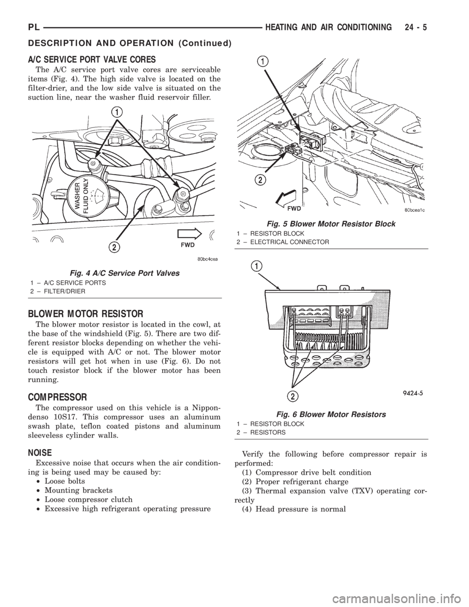
The A/C service port valve cores are serviceable
items (Fig. 4). The high side valve is located on the
filter-drier, and the low side valve is situated on the
suction line, near the washer fluid reservoir filler.
BLOWER MOTOR RESISTOR
The blower motor resistor is located in the cowl, at
the base of the windshield (Fig. 5). There are two dif-
ferent resistor blocks depending on whether the vehi-
cle is equipped with A/C or not. The blower motor
resistors will get hot when in use (Fig. 6). Do not
touch resistor block if the blower motor has been
running.
COMPRESSOR
The compressor used on this vehicle is a Nippon-
denso 10S17. This compressor uses an aluminum
swash plate, teflon coated pistons and aluminum
sleeveless cylinder walls.
NOISE
Excessive noise that occurs when the air condition-
ing is being used may be caused by:
²Loose bolts
²Mounting brackets
²Loose compressor clutch
²Excessive high refrigerant operating pressureVerify the following before compressor repair is
performed:
(1) Compressor drive belt condition
(2) Proper refrigerant charge
(3) Thermal expansion valve (TXV) operating cor-
rectly
(4) Head pressure is normal
Fig. 4 A/C Service Port Valves
1 ± A/C SERVICE PORTS
2 ± FILTER/DRIER
Fig. 5 Blower Motor Resistor Block
1 ± RESISTOR BLOCK
2 ± ELECTRICAL CONNECTOR
Fig. 6 Blower Motor Resistors
1 ± RESISTOR BLOCK
2 ± RESISTORS
PLHEATING AND AIR CONDITIONING 24 - 5
DESCRIPTION AND OPERATION (Continued)
Page 1240 of 1285
Normally, vacuum is supplied to the actuator by
placing the Circulation control knob in the Recircula-
tion position. The Mode and the circulation control
are mechanically interlocked so the circulation con-
trol cannot be placed in the RECIRC position if the
mode control is at or between the mix and defrost
positions. Vacuum is supplied to the actuator only
when circulation control is at the RECIRC position.
If the circulation control is between the outside air
position and RECIRC position the system will be in
outside air. If the circulation control is in the
RECIRC position and the mode control is moved from
the floor to the defrost positions, the circulation con-
trol will move from the RECIRC position, to the out-
side air position beginning at the mix position. This
is to prevent window fogging.
DIAGNOSIS AND TESTING
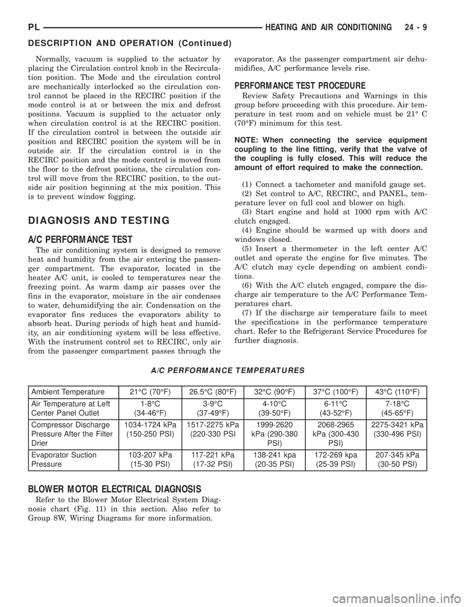
A/C PERFORMANCE TEST
The air conditioning system is designed to remove
heat and humidity from the air entering the passen-
ger compartment. The evaporator, located in the
heater A/C unit, is cooled to temperatures near the
freezing point. As warm damp air passes over the
fins in the evaporator, moisture in the air condenses
to water, dehumidifying the air. Condensation on the
evaporator fins reduces the evaporators ability to
absorb heat. During periods of high heat and humid-
ity, an air conditioning system will be less effective.
With the instrument control set to RECIRC, only air
from the passenger compartment passes through theevaporator. As the passenger compartment air dehu-
midifies, A/C performance levels rise.
PERFORMANCE TEST PROCEDURE
Review Safety Precautions and Warnings in this
group before proceeding with this procedure. Air tem-
perature in test room and on vehicle must be 21É C
(70ÉF) minimum for this test.
NOTE: When connecting the service equipment
coupling to the line fitting, verify that the valve of
the coupling is fully closed. This will reduce the
amount of effort required to make the connection.
(1) Connect a tachometer and manifold gauge set.
(2) Set control to A/C, RECIRC, and PANEL, tem-
perature lever on full cool and blower on high.
(3) Start engine and hold at 1000 rpm with A/C
clutch engaged.
(4) Engine should be warmed up with doors and
windows closed.
(5) Insert a thermometer in the left center A/C
outlet and operate the engine for five minutes. The
A/C clutch may cycle depending on ambient condi-
tions.
(6) With the A/C clutch engaged, compare the dis-
charge air temperature to the A/C Performance Tem-
peratures chart.
(7) If the discharge air temperature fails to meet
the specifications in the performance temperature
chart. Refer to the Refrigerant Service Procedures for
further diagnosis.
A/C PERFORMANCE TEMPERATURES
Ambient Temperature 21ÉC (70ÉF) 26.5ÉC (80ÉF) 32ÉC (90ÉF) 37ÉC (100ÉF) 43ÉC (110ÉF)
Air Temperature at Left
Center Panel Outlet1-8ÉC
(34-46ÉF)3-9ÉC
(37-49ÉF)4-10ÉC
(39-50ÉF)6-11ÉC
(43-52ÉF)7-18ÉC
(45-65ÉF)
Compressor Discharge
Pressure After the Filter
Drier1034-1724 kPa
(150-250 PSI)1517-2275 kPa
(220-330 PSI1999-2620
kPa (290-380
PSI)2068-2965
kPa (300-430
PSI)2275-3421 kPa
(330-496 PSI)
Evaporator Suction
Pressure103-207 kPa
(15-30 PSI)117-221 kPa
(17-32 PSI)138-241 kpa
(20-35 PSI)172-269 kpa
(25-39 PSI)207-345 kPa
(30-50 PSI)
BLOWER MOTOR ELECTRICAL DIAGNOSIS
Refer to the Blower Motor Electrical System Diag-
nosis chart (Fig. 11) in this section. Also refer to
Group 8W, Wiring Diagrams for more information.
PLHEATING AND AIR CONDITIONING 24 - 9
DESCRIPTION AND OPERATION (Continued)
Page 1241 of 1285
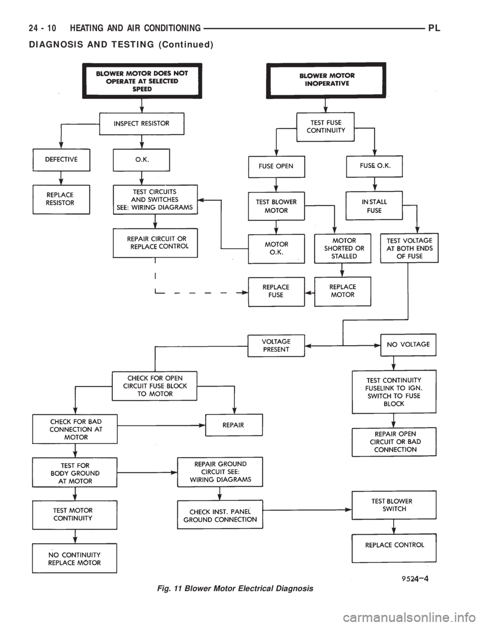
Fig. 11 Blower Motor Electrical Diagnosis
24 - 10 HEATING AND AIR CONDITIONINGPL
DIAGNOSIS AND TESTING (Continued)
Page 1253 of 1285
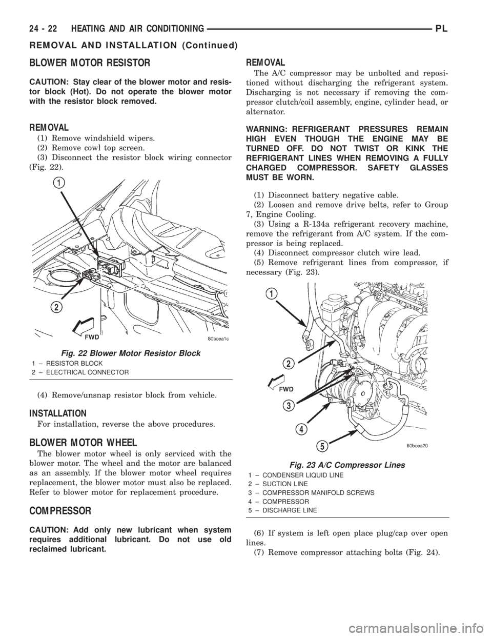
BLOWER MOTOR RESISTOR
CAUTION: Stay clear of the blower motor and resis-
tor block (Hot). Do not operate the blower motor
with the resistor block removed.
REMOVAL
(1) Remove windshield wipers.
(2) Remove cowl top screen.
(3) Disconnect the resistor block wiring connector
(Fig. 22).
(4) Remove/unsnap resistor block from vehicle.
INSTALLATION
For installation, reverse the above procedures.
BLOWER MOTOR WHEEL
The blower motor wheel is only serviced with the
blower motor. The wheel and the motor are balanced
as an assembly. If the blower motor wheel requires
replacement, the blower motor must also be replaced.
Refer to blower motor for replacement procedure.
COMPRESSOR
CAUTION: Add only new lubricant when system
requires additional lubricant. Do not use old
reclaimed lubricant.
REMOVAL
The A/C compressor may be unbolted and reposi-
tioned without discharging the refrigerant system.
Discharging is not necessary if removing the com-
pressor clutch/coil assembly, engine, cylinder head, or
alternator.
WARNING: REFRIGERANT PRESSURES REMAIN
HIGH EVEN THOUGH THE ENGINE MAY BE
TURNED OFF. DO NOT TWIST OR KINK THE
REFRIGERANT LINES WHEN REMOVING A FULLY
CHARGED COMPRESSOR. SAFETY GLASSES
MUST BE WORN.
(1) Disconnect battery negative cable.
(2) Loosen and remove drive belts, refer to Group
7, Engine Cooling.
(3) Using a R-134a refrigerant recovery machine,
remove the refrigerant from A/C system. If the com-
pressor is being replaced.
(4) Disconnect compressor clutch wire lead.
(5) Remove refrigerant lines from compressor, if
necessary (Fig. 23).
(6) If system is left open place plug/cap over open
lines.
(7) Remove compressor attaching bolts (Fig. 24).
Fig. 22 Blower Motor Resistor Block
1 ± RESISTOR BLOCK
2 ± ELECTRICAL CONNECTOR
Fig. 23 A/C Compressor Lines
1 ± CONDENSER LIQUID LINE
2 ± SUCTION LINE
3 ± COMPRESSOR MANIFOLD SCREWS
4 ± COMPRESSOR
5 ± DISCHARGE LINE
24 - 22 HEATING AND AIR CONDITIONINGPL
REMOVAL AND INSTALLATION (Continued)
Page 1262 of 1285
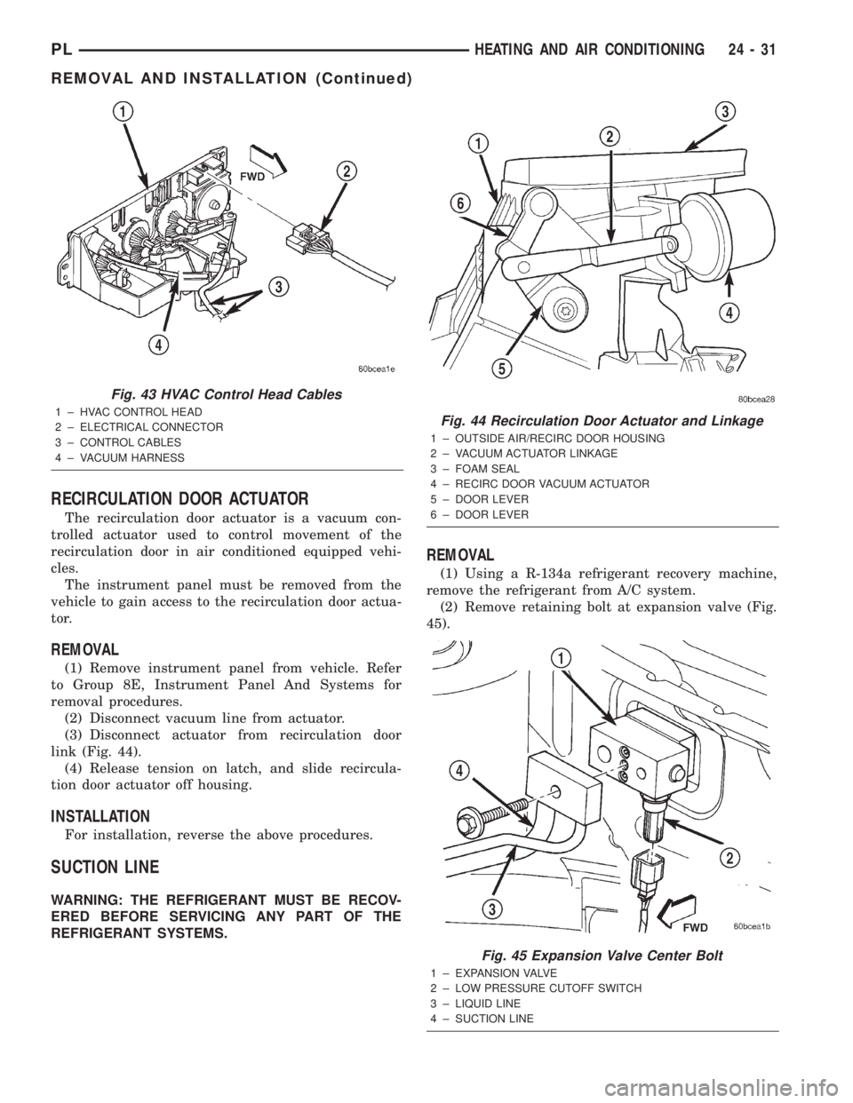
RECIRCULATION DOOR ACTUATOR
The recirculation door actuator is a vacuum con-
trolled actuator used to control movement of the
recirculation door in air conditioned equipped vehi-
cles.
The instrument panel must be removed from the
vehicle to gain access to the recirculation door actua-
tor.
REMOVAL
(1) Remove instrument panel from vehicle. Refer
to Group 8E, Instrument Panel And Systems for
removal procedures.
(2) Disconnect vacuum line from actuator.
(3) Disconnect actuator from recirculation door
link (Fig. 44).
(4) Release tension on latch, and slide recircula-
tion door actuator off housing.
INSTALLATION
For installation, reverse the above procedures.
SUCTION LINE
WARNING: THE REFRIGERANT MUST BE RECOV-
ERED BEFORE SERVICING ANY PART OF THE
REFRIGERANT SYSTEMS.
REMOVAL
(1) Using a R-134a refrigerant recovery machine,
remove the refrigerant from A/C system.
(2) Remove retaining bolt at expansion valve (Fig.
45).
Fig. 43 HVAC Control Head Cables
1 ± HVAC CONTROL HEAD
2 ± ELECTRICAL CONNECTOR
3 ± CONTROL CABLES
4 ± VACUUM HARNESSFig. 44 Recirculation Door Actuator and Linkage
1 ± OUTSIDE AIR/RECIRC DOOR HOUSING
2 ± VACUUM ACTUATOR LINKAGE
3 ± FOAM SEAL
4 ± RECIRC DOOR VACUUM ACTUATOR
5 ± DOOR LEVER
6 ± DOOR LEVER
Fig. 45 Expansion Valve Center Bolt
1 ± EXPANSION VALVE
2 ± LOW PRESSURE CUTOFF SWITCH
3 ± LIQUID LINE
4 ± SUCTION LINE
PLHEATING AND AIR CONDITIONING 24 - 31
REMOVAL AND INSTALLATION (Continued)
Page 1264 of 1285
(6) Remove expansion valve from evaporator, and
cap fittings.
(7) Remove rubber drain tube extension from con-
densation drain tube.
(8) Disconnect the vacuum harness at the power
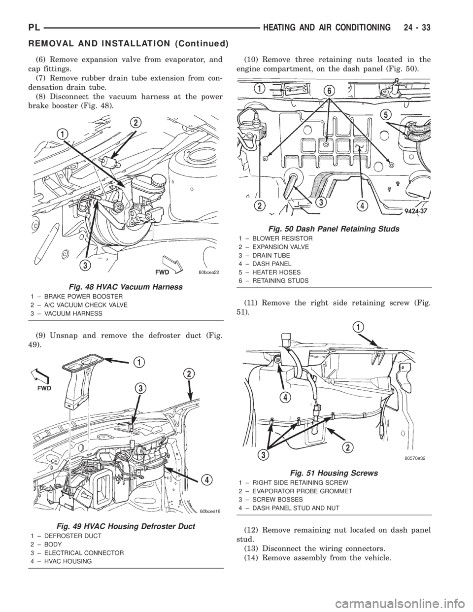
brake booster (Fig. 48).
(9) Unsnap and remove the defroster duct (Fig.
49).(10) Remove three retaining nuts located in the
engine compartment, on the dash panel (Fig. 50).
(11) Remove the right side retaining screw (Fig.
51).
(12) Remove remaining nut located on dash panel
stud.
(13) Disconnect the wiring connectors.
(14) Remove assembly from the vehicle.
Fig. 48 HVAC Vacuum Harness
1 ± BRAKE POWER BOOSTER
2 ± A/C VACUUM CHECK VALVE
3 ± VACUUM HARNESS
Fig. 49 HVAC Housing Defroster Duct
1 ± DEFROSTER DUCT
2 ± BODY
3 ± ELECTRICAL CONNECTOR
4 ± HVAC HOUSING
Fig. 50 Dash Panel Retaining Studs
1 ± BLOWER RESISTOR
2 ± EXPANSION VALVE
3 ± DRAIN TUBE
4 ± DASH PANEL
5 ± HEATER HOSES
6 ± RETAINING STUDS
Fig. 51 Housing Screws
1 ± RIGHT SIDE RETAINING SCREW
2 ± EVAPORATOR PROBE GROMMET
3 ± SCREW BOSSES
4 ± DASH PANEL STUD AND NUT
PLHEATING AND AIR CONDITIONING 24 - 33
REMOVAL AND INSTALLATION (Continued)
Page 1268 of 1285
HEATING AND AIR CONDITIONING
TABLE OF CONTENTS
page page
REMOVAL AND INSTALLATION
EVAPORATOR CORE ± R. H. D...............1
HEATER CORE ± R. H. D....................3SPECIFICATIONS
TORQUE SPECIFICATIONS..................6
REMOVAL AND INSTALLATION
EVAPORATOR CORE ± R. H. D.
REMOVAL
WARNING: ON VEHICLES EQUIPPED WITH AIR-
BAGS, REFER TO GROUP 8M ± PASSIVE
RESTRAINT SYSTEMS BEFORE ATTEMPTING ANY
STEERING WHEEL, STEERING COLUMN, OR
INSTRUMENT PANEL COMPONENT DIAGNOSIS OR
SERVICE. FAILURE TO TAKE THE PROPER PRE-
CAUTIONS COULD RESULT IN ACCIDENTAL AIR-
BAG DEPLOYMENT AND POSSIBLE PERSONAL
INJURY.
WARNING: DO NOT OPEN THE RADIATOR DRAIN-
COCK OR DISCONNECT COOLANT HOSES WHEN
THE COOLING SYSTEM IS HOT AND UNDER PRES-
SURE. SERIOUS BURNS FROM COOLANT CAN
OCCUR.
WARNING: READ ALL SAFETY PRECAUTIONS AND
WARNINGS BEFORE PROCEEDING WITH THIS
OPERATION.
(1) Disconnect the negative battery cable.
(2) Drain the cooling system. Refer to Group 7,
Cooling System for the procedure.
(3) Evacuate the refrigerant system.
(4) Remove the instrument panel. Refer to Group
8E, Instrument Panel and Systems for the procedure.
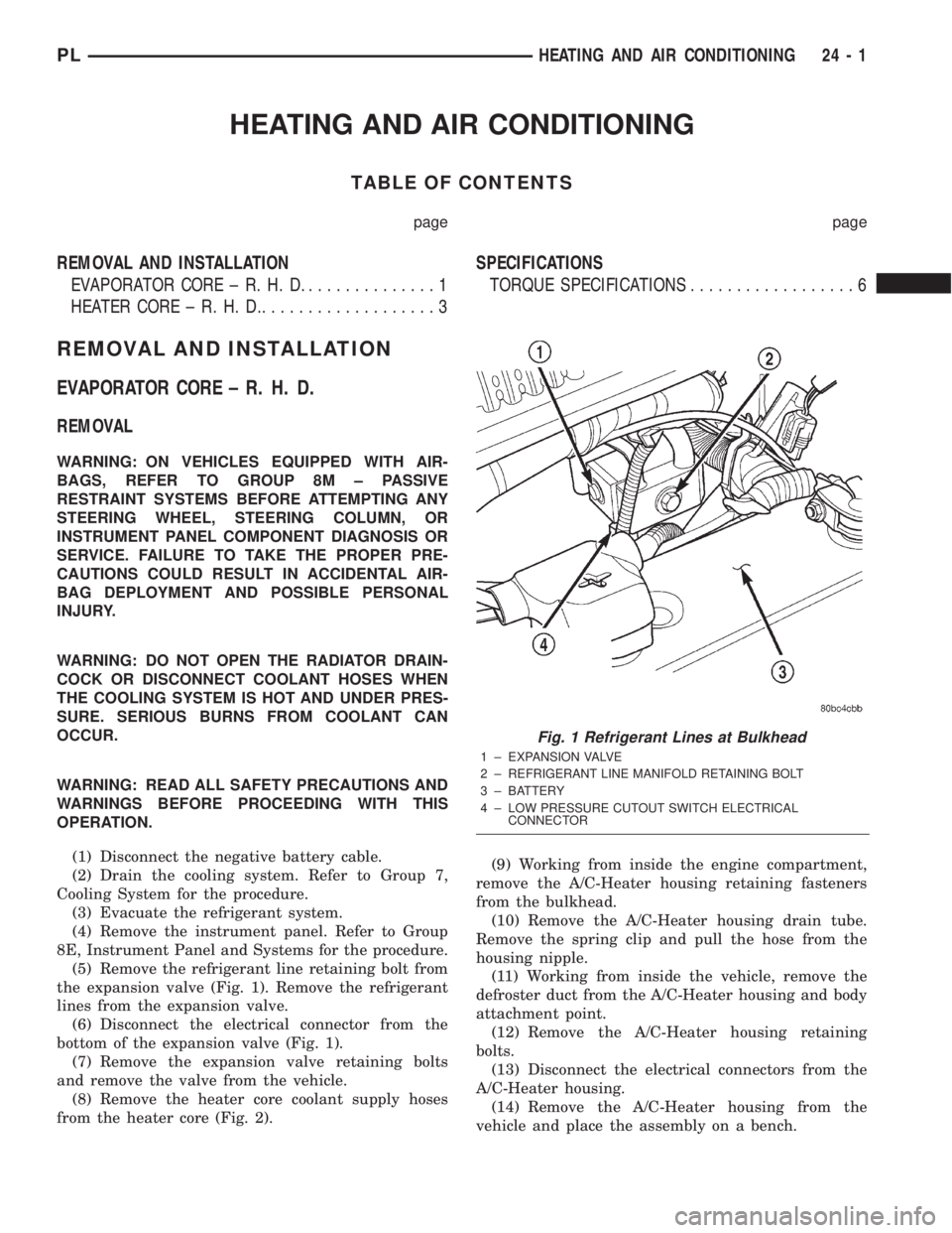
(5) Remove the refrigerant line retaining bolt from
the expansion valve (Fig. 1). Remove the refrigerant
lines from the expansion valve.
(6) Disconnect the electrical connector from the
bottom of the expansion valve (Fig. 1).
(7) Remove the expansion valve retaining bolts
and remove the valve from the vehicle.
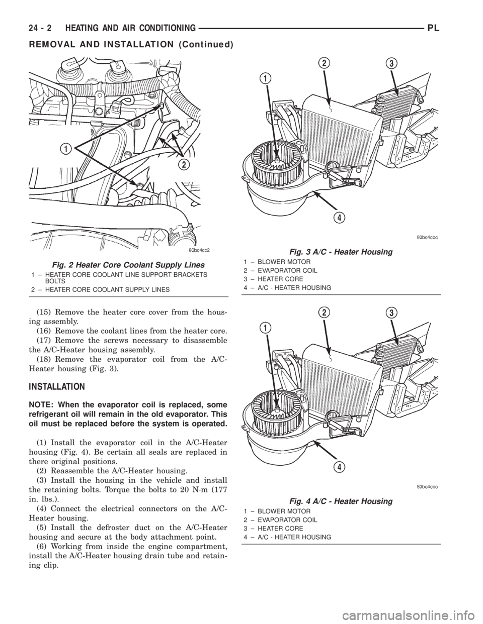
(8) Remove the heater core coolant supply hoses
from the heater core (Fig. 2).(9) Working from inside the engine compartment,
remove the A/C-Heater housing retaining fasteners
from the bulkhead.
(10) Remove the A/C-Heater housing drain tube.
Remove the spring clip and pull the hose from the
housing nipple.
(11) Working from inside the vehicle, remove the
defroster duct from the A/C-Heater housing and body
attachment point.
(12) Remove the A/C-Heater housing retaining
bolts.
(13) Disconnect the electrical connectors from the
A/C-Heater housing.
(14) Remove the A/C-Heater housing from the
vehicle and place the assembly on a bench.
Fig. 1 Refrigerant Lines at Bulkhead
1 ± EXPANSION VALVE
2 ± REFRIGERANT LINE MANIFOLD RETAINING BOLT
3 ± BATTERY
4 ± LOW PRESSURE CUTOUT SWITCH ELECTRICAL
CONNECTOR
PLHEATING AND AIR CONDITIONING 24 - 1
Page 1269 of 1285
(15) Remove the heater core cover from the hous-
ing assembly.
(16) Remove the coolant lines from the heater core.
(17) Remove the screws necessary to disassemble
the A/C-Heater housing assembly.
(18) Remove the evaporator coil from the A/C-
Heater housing (Fig. 3).
INSTALLATION
NOTE: When the evaporator coil is replaced, some
refrigerant oil will remain in the old evaporator. This
oil must be replaced before the system is operated.
(1) Install the evaporator coil in the A/C-Heater
housing (Fig. 4). Be certain all seals are replaced in
there original positions.
(2) Reassemble the A/C-Heater housing.
(3) Install the housing in the vehicle and install
the retaining bolts. Torque the bolts to 20 N´m (177
in. lbs.).
(4) Connect the electrical connectors on the A/C-
Heater housing.
(5) Install the defroster duct on the A/C-Heater
housing and secure at the body attachment point.
(6) Working from inside the engine compartment,
install the A/C-Heater housing drain tube and retain-
ing clip.
Fig. 2 Heater Core Coolant Supply Lines
1 ± HEATER CORE COOLANT LINE SUPPORT BRACKETS
BOLTS
2 ± HEATER CORE COOLANT SUPPLY LINES
Fig. 3 A/C - Heater Housing
1 ± BLOWER MOTOR
2 ± EVAPORATOR COIL
3 ± HEATER CORE
4 ± A/C - HEATER HOUSING
Fig. 4 A/C - Heater Housing
1 ± BLOWER MOTOR
2 ± EVAPORATOR COIL
3 ± HEATER CORE
4 ± A/C - HEATER HOUSING
24 - 2 HEATING AND AIR CONDITIONINGPL
REMOVAL AND INSTALLATION (Continued)