2000 DODGE NEON electrical
[x] Cancel search: electricalPage 760 of 1285
CYLINDER HEAD
REMOVAL
(1) Perform fuel system pressure release procedure
before attempting any repairs.Refer to Group 14,
Fuel System
(2) Disconnect negative battery cable.
(3) Remove power steering/air conditioning drive
belt. Refer to Group 7, Cooling System Accessory
Drive for procedure.
(4) Raise vehicle.
(5) Drain cooling system. Refer to Group 7, Cooling
System.
(6) Remove exhaust pipe from manifold.
(7) Remove right front wheel.
(8) Remove right side splash shield.
(9) Remove generator belt. Refer to Group 7, Cool-
ing System Accessory Drive Belts for procedure.
(10) Remove crankshaft damper. Refer to proce-
dure in this section.
(11) Remove lower torque strut.
(12) Lower vehicle and remove upper torque strut.
(13) Remove ground strap and power steering hose
support clip from engine mount bracket.
(14) Remove power steering pump assembly and
set aside.
(15) Support engine from beneath with a suitable
jack.
(16) Remove right side engine mount to bracket
through bolt.
(17) Remove the lower engine mount bracket bolt.
Raise engine slightly and remove the upper engine
mount bracket bolts.(18) Remove engine mount bracket. This procedure
may require additional raising/lowering of engine
until bracket will clear engine components.
(19) Remove front timing belt cover.
(20) Rotate engine until timing marks are aligned.
(21) Remove timing belt and tensioner. Refer to
procedures in this section.
(22) Remove camshaft sprocket. Refer to proce-
dures in this section.
(23) Remove rear timing belt cover.
(24) Disconnect fuel line at fuel rail.
(25) Remove coolant recovery container.
(26) Remove ground wire to cylinder head.
(27) Remove upper radiator hose.
(28) Remove intake manifold. Refer to procedure
in this section.
(29) Disconnect ignition coil electrical connector.
Remove coil pack and spark plug cables from engine.
(30) Remove Crankcase Closed Ventilation (CCV)
hose from cylinder head cover.
(31) Disconnect cam sensor and coolant tempera-
ture electrical connectors.
(32) Remove heater tube to cylinder head attach-
ing fasteners.
(33) Remove heater hose from thermostat housing
connector.
(34) Remove cylinder head cover.
(35) Remove cylinder head bolts.
(36) Remove cylinder head and gasket (Fig. 55).
PL2.0L SOHC ENGINE 9 - 37
REMOVAL AND INSTALLATION (Continued)
Page 762 of 1285
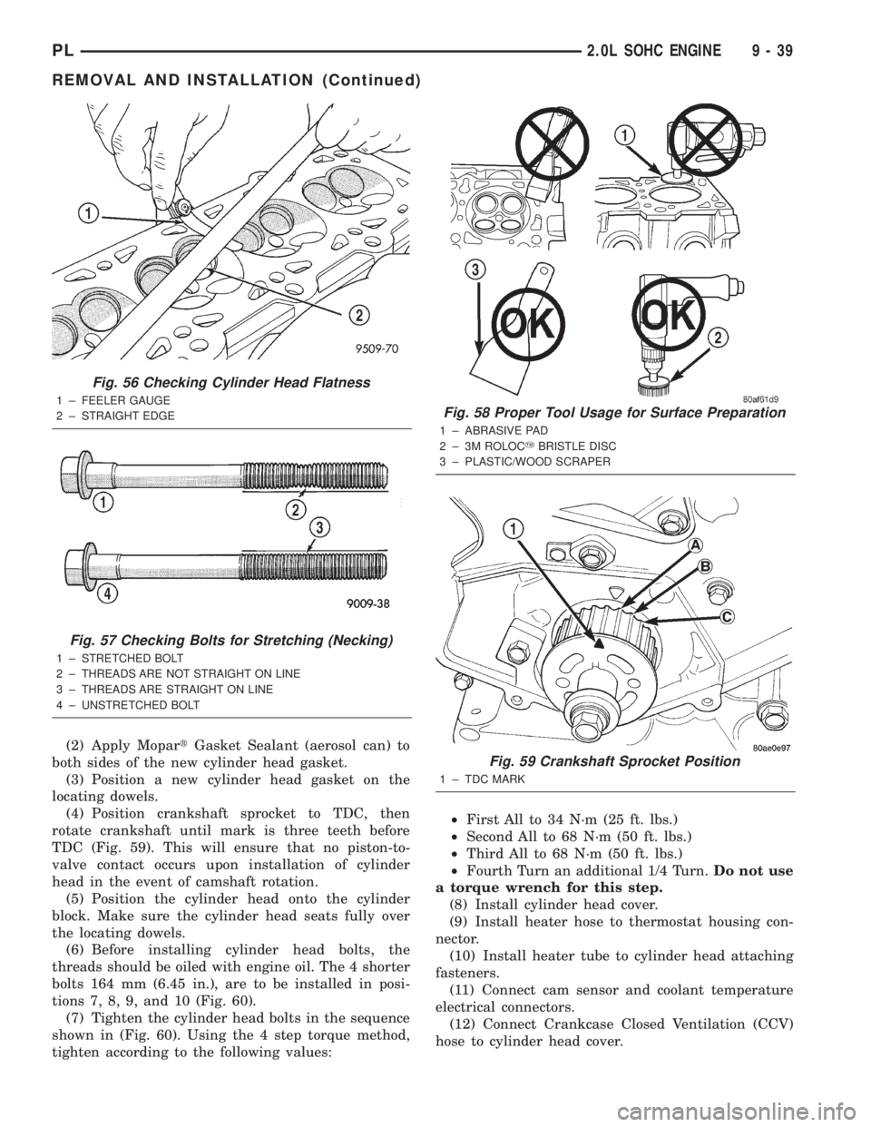
(2) Apply MopartGasket Sealant (aerosol can) to
both sides of the new cylinder head gasket.
(3) Position a new cylinder head gasket on the
locating dowels.
(4) Position crankshaft sprocket to TDC, then
rotate crankshaft until mark is three teeth before
TDC (Fig. 59). This will ensure that no piston-to-
valve contact occurs upon installation of cylinder
head in the event of camshaft rotation.
(5) Position the cylinder head onto the cylinder
block. Make sure the cylinder head seats fully over
the locating dowels.
(6) Before installing cylinder head bolts, the
threads should be oiled with engine oil. The 4 shorter
bolts 164 mm (6.45 in.), are to be installed in posi-
tions 7, 8, 9, and 10 (Fig. 60).
(7) Tighten the cylinder head bolts in the sequence
shown in (Fig. 60). Using the 4 step torque method,
tighten according to the following values:²First All to 34 N´m (25 ft. lbs.)
²Second All to 68 N´m (50 ft. lbs.)
²Third All to 68 N´m (50 ft. lbs.)
²Fourth Turn an additional 1/4 Turn.Do not use
a torque wrench for this step.
(8) Install cylinder head cover.
(9) Install heater hose to thermostat housing con-
nector.
(10) Install heater tube to cylinder head attaching
fasteners.
(11) Connect cam sensor and coolant temperature
electrical connectors.
(12) Connect Crankcase Closed Ventilation (CCV)
hose to cylinder head cover.
Fig. 56 Checking Cylinder Head Flatness
1 ± FEELER GAUGE
2 ± STRAIGHT EDGE
Fig. 57 Checking Bolts for Stretching (Necking)
1 ± STRETCHED BOLT
2 ± THREADS ARE NOT STRAIGHT ON LINE
3 ± THREADS ARE STRAIGHT ON LINE
4 ± UNSTRETCHED BOLT
Fig. 58 Proper Tool Usage for Surface Preparation
1 ± ABRASIVE PAD
2 ± 3M ROLOCYBRISTLE DISC
3 ± PLASTIC/WOOD SCRAPER
Fig. 59 Crankshaft Sprocket Position
1 ± TDC MARK
PL2.0L SOHC ENGINE 9 - 39
REMOVAL AND INSTALLATION (Continued)
Page 763 of 1285

(13) Install ignition coil and spark plug cables.
Connect coil electrical connector.
(14) Install intake manifold. Refer to procedure in
this section.
(15) Install upper radiator hose.
(16) Install ground wire to cylinder head.
(17) Install coolant recovery container.
(18) Connect fuel line to fuel rail.
(19) Install rear timing belt cover, camshaft
sprocket, and timing belt tensioner and timing belt.
Refer to procedures in this section.
(20) Install front timing belt cover.
(21) Install engine mount bracket.
(22) Position engine and install right side engine
mount to engine mount bracket bolt. Tighten bolt to
118 N´m (87 ft. lbs.). Remove jack from beneath
engine.
(23) Install power steering pump assembly.
(24) Install power steering hose support clip and
ground strap to engine mount bracket.
(25) Install upper torque strut.
(26) Raise vehicle.
(27) Install lower torque strut.
(28) Install crankshaft damper.
(29) Install accessory drive belts. Refer to Group 7,
Cooling System Accessory Drive Belt for procedure.
(30) Install right side splash shield and front
wheel.
(31) Install exhaust pipe to exhaust manifold
flange.
(32) Lower vehicle and fill cooling system. Refer to
Group 7, Cooling System for procedure.
(33) Connect negative cable to battery.
(34) Perform camshaft and crankshaft timing
relearn procedure as follows:
²Connect the DRB scan tool to the data link
(diagnostic) connector. This connector is located in
the passenger compartment; at the lower edge of
instrument panel; near the steering column.
²Turn the ignition switch on and access the ªmis-
cellaneousº screen.
²Select ªre-learn cam/crankº option and follow
directions on DRB screen.
CRANKSHAFT DAMPER
REMOVAL
(1) Remove accessory drive belts. Refer to Group 7,
Cooling System for procedure.
(2) Raise vehicle on a hoist and remove right inner
splash shield.
(3) Remove crankshaft damper bolt. Remove
damper using the large side of Special Tool 1026 and
insert 6827-A (Fig. 61).
INSTALLATION
(1) Install crankshaft damper using M12±1.75 x
150 mm bolt, washer, thrust bearing and nut from
Special Tool 6792 (Fig. 62).
Fig. 62 Crankshaft DamperÐInstallation
1 ± M12 Ð 1.753150 MM BOLT, WASHER AND THRUST
BEARING FROM SPECIAL TOOL 6792
Fig. 60 Cylinder Head Tightening Sequence
Fig. 61 Crankshaft DamperÐRemoval
1 ± SPECIAL TOOL 6827±A INSERT
2 ± SPECIAL TOOL 1026 THREE JAW PULLER
9 - 40 2.0L SOHC ENGINEPL
REMOVAL AND INSTALLATION (Continued)
Page 805 of 1285
(2) Install exhaust manifold support bracket (Fed-
eral and LEV only). Tighten M10 bolt to 54 N´m (40
ft. lbs.), M12 bolt to 95 N´m (70 ft. lbs.), and nut to
28 N´m (250 in. lbs.).
(3) Install bolt attaching manifold support bracket
to the heat shield (Federal and LEV only). Tighten
bolt to 28 N´m (250 in. lbs.).
(4) Assemble muffler and exhaust pipe to catalytic
converter. Install muffler and pipe support isolators
to the underbody.
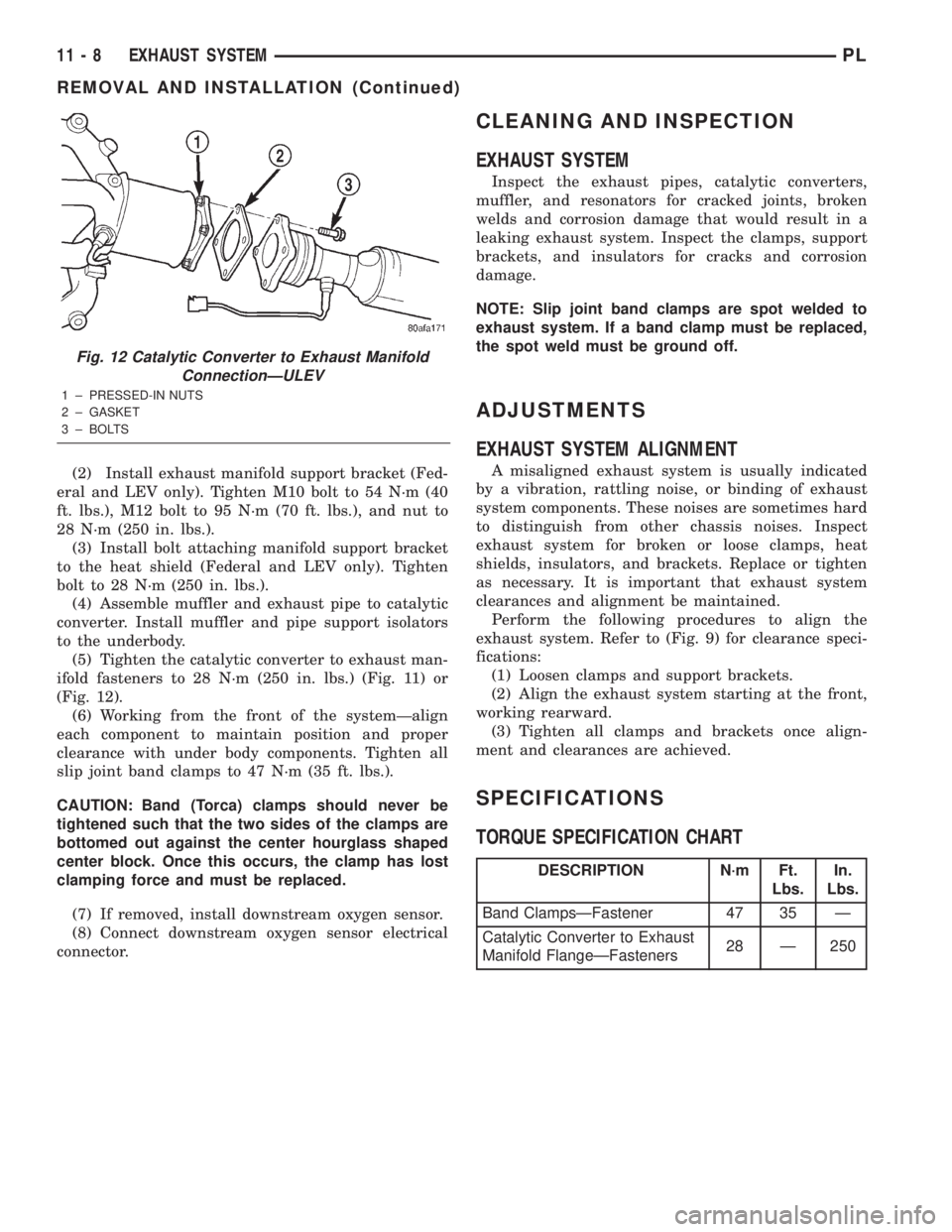
(5) Tighten the catalytic converter to exhaust man-
ifold fasteners to 28 N´m (250 in. lbs.) (Fig. 11) or
(Fig. 12).
(6) Working from the front of the systemÐalign
each component to maintain position and proper
clearance with under body components. Tighten all
slip joint band clamps to 47 N´m (35 ft. lbs.).
CAUTION: Band (Torca) clamps should never be
tightened such that the two sides of the clamps are
bottomed out against the center hourglass shaped
center block. Once this occurs, the clamp has lost
clamping force and must be replaced.
(7) If removed, install downstream oxygen sensor.
(8) Connect downstream oxygen sensor electrical
connector.
CLEANING AND INSPECTION
EXHAUST SYSTEM
Inspect the exhaust pipes, catalytic converters,
muffler, and resonators for cracked joints, broken
welds and corrosion damage that would result in a
leaking exhaust system. Inspect the clamps, support
brackets, and insulators for cracks and corrosion
damage.
NOTE: Slip joint band clamps are spot welded to
exhaust system. If a band clamp must be replaced,
the spot weld must be ground off.
ADJUSTMENTS
EXHAUST SYSTEM ALIGNMENT
A misaligned exhaust system is usually indicated
by a vibration, rattling noise, or binding of exhaust
system components. These noises are sometimes hard
to distinguish from other chassis noises. Inspect
exhaust system for broken or loose clamps, heat
shields, insulators, and brackets. Replace or tighten
as necessary. It is important that exhaust system
clearances and alignment be maintained.
Perform the following procedures to align the
exhaust system. Refer to (Fig. 9) for clearance speci-
fications:
(1) Loosen clamps and support brackets.
(2) Align the exhaust system starting at the front,
working rearward.
(3) Tighten all clamps and brackets once align-
ment and clearances are achieved.
SPECIFICATIONS
TORQUE SPECIFICATION CHART
Fig. 12 Catalytic Converter to Exhaust Manifold
ConnectionÐULEV
1 ± PRESSED-IN NUTS
2 ± GASKET
3 ± BOLTS
DESCRIPTION N´m Ft.
Lbs.In.
Lbs.
Band ClampsÐFastener 47 35 Ð
Catalytic Converter to Exhaust
Manifold FlangeÐFasteners28 Ð 250
11 - 8 EXHAUST SYSTEMPL
REMOVAL AND INSTALLATION (Continued)
Page 825 of 1285
The inlet strainer, fuel pressure regulator and fuel
level sensor are the only serviceable items. If the fuel
pump requires service, replace the fuel pump module.
ELECTRIC FUEL PUMP
DESCRIPTION
The electric fuel pump is located in and is part of
the fuel pump module. It is a positive displacement,
gerotor type, immersible pump with a permanent
magnet electric motor. The fuel pump module is sus-
pended in fuel in the fuel tank.
OPERATION
The pump draws fuel through a strainer and
pushes it through the motor to the outlet. The pump
contains a check valve. The valve, in the pump out-
let, maintains pump pressure during engine off con-
ditions. The fuel pump relay provides voltage to the
fuel pump. The fuel pump has a maximum dead-
headed pressure output of approximately 880 kPa
(130 psi). The regulator adjusts fuel system pressure
to approximately 338 kPa (49 psi).
FUEL GAUGE SENDING UNIT
DESCRIPTION
The fuel gauge sending unit (fuel level sensor) is
attached to the side of the fuel pump module. The
sending unit consists of a float, an arm, and a vari-
able resistor (track). The resistor track is used to
send electrical signals to the instrument cluster for
fuel gauge operation and are then transmitted to the
engine controller for OBDII emission requirements.
OPERATION
For fuel gauge operation:As fuel level
increases, the float and arm move up. This increases
the sending unit resistance, causing the fuel gauge to
read full. As fuel level decreases, the float and arm
move down. This decreases the sending unit resis-
tance causing the fuel gauge to read empty.
After this fuel level signal is sent to the instru-
ment cluster, the instrument cluster will transmit
the data across the J1850 bus circuit to the PCM.
For OBD II emission requirements:The voltage
signal is sent to the instrument cluster to indicate
fuel level. The cluster transmits the fuel level to the
PCM where it is used to prevent a false setting of
misfire and fuel system monitor trouble codes. This
occurs if the fuel level in the tank is less than
approximately 15 percent of its rated capacity.
FUEL FILTER/FUEL PRESSURE REGULATOR
DESCRIPTION
A combination fuel filter and fuel pressure regula-
tor is used on all gas powered engines. It is located
on the top of the fuel pump module. A separate frame
mounted fuel filter is not used.
OPERATION
Fuel Pressure Regulator Operation:The pres-
sure regulator is a mechanical device that is cali-
brated to maintain fuel system operating pressure of
approximately 338 kPa (49 psi) at the fuel injectors.
It contains a diaphragm, calibrated springs and a
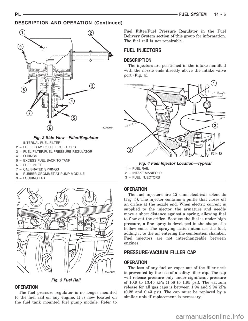
fuel return valve. The internal fuel filter (Fig. 2) is
also part of the assembly.
Fuel is supplied to the filter/regulator by the elec-
tric fuel pump through an opening tube at the bot-
tom of filter/regulator.
The fuel pump module contains a check valve to
maintain some fuel pressure when the engine is not
operating. This will help to start the engine.
If fuel pressure at the pressure regulator exceeds
approximately 49 psi, an internal diaphragm closes
and excess fuel pressure is routed back into the tank
through the pressure regulator. A separate fuel
return line is not used with any gas powered engine.
FUEL TANK
OPERATION
All models pass a full 360 degree rollover test
without fuel leakage. To accomplish this, fuel and
vapor flow controls are required for all fuel tank con-
nections.
All models are equipped with either one or two
rollover valves mounted into the top of the fuel tank
(or pump module).
An evaporation control system is connected to the
rollover valve(s) to reduce emissions of fuel vapors
into the atmosphere. When fuel evaporates from the
fuel tank, vapors pass through vent hoses or tubes to
a charcoal canister where they are temporarily held.
When the engine is running, the vapors are drawn
into the intake manifold. Certain models are also
equipped with a self-diagnosing system using a Leak
Detection Pump (LDP). Refer to the Emission Control
System for additional information.
FUEL RAIL
DESCRIPTION
The fuel rail supplies the necessary fuel to each
individual fuel injector and is mounted to the intake
manifold (Fig. 3).
14 - 4 FUEL SYSTEMPL
DESCRIPTION AND OPERATION (Continued)
Page 826 of 1285
OPERATION
The fuel pressure regulator is no longer mounted
to the fuel rail on any engine. It is now located on
the fuel tank mounted fuel pump module. Refer toFuel Filter/Fuel Pressure Regulator in the Fuel
Delivery System section of this group for information.
The fuel rail is not repairable.
FUEL INJECTORS
DESCRIPTION
The injectors are positioned in the intake manifold
with the nozzle ends directly above the intake valve
port (Fig. 4).
OPERATION
The fuel injectors are 12 ohm electrical solenoids
(Fig. 5). The injector contains a pintle that closes off
an orifice at the nozzle end. When electric current is
supplied to the injector, the armature and needle
move a short distance against a spring, allowing fuel
to flow out the orifice. Because the fuel is under high
pressure, a fine spray is developed in the shape of a
hollow cone. The spraying action atomizes the fuel,
adding it to the air entering the combustion chamber.
Fuel injectors are not interchangeable between
engines.
PRESSURE-VACUUM FILLER CAP
OPERATION
The loss of any fuel or vapor out of the filler neck
is prevented by the use of a safety filler cap. The cap
will release pressure only under significant pressure
of 10.9 to 13.45 kPa (1.58 to 1.95 psi). The vacuum
release for all gas caps is between 1.94 and 2.94 kPa
(0.28 and 0.43 psi). The cap must be replaced by a
similar unit if replacement is necessary.
Fig. 2 Side ViewÐFilter/Regulator
1 ± INTERNAL FUEL FILTER
2 ± FUEL FLOW TO FUEL INJECTORS
3 ± FUEL FILTER/FUEL PRESSURE REGULATOR
4 ± O-RINGS
5 ± EXCESS FUEL BACK TO TANK
6 ± FUEL INLET
7 ± CALIBRATED SPRINGS
8 ± RUBBER GROMMET AT PUMP MODULE
9 ± LOCKING TAB
Fig. 3 Fuel Rail
Fig. 4 Fuel Injector LocationÐTypical
1 ± FUEL RAIL
2 ± INTAKE MANIFOLD
3 ± FUEL INJECTORS
PLFUEL SYSTEM 14 - 5
DESCRIPTION AND OPERATION (Continued)
Page 829 of 1285
FUEL TUBES/LINES/HOSES AND CLAMPS
OPERATION
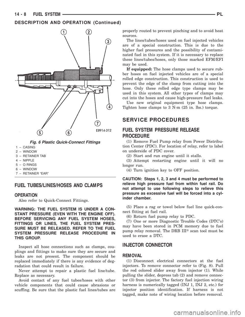
Also refer to Quick-Connect Fittings.
WARNING: THE FUEL SYSTEM IS UNDER A CON-
STANT PRESSURE (EVEN WITH THE ENGINE OFF).
BEFORE SERVICING ANY FUEL SYSTEM HOSES,
FITTINGS OR LINES, THE FUEL SYSTEM PRES-
SURE MUST BE RELEASED. REFER TO THE FUEL
SYSTEM PRESSURE RELEASE PROCEDURE IN
THIS GROUP.
Inspect all hose connections such as clamps, cou-
plings and fittings to make sure they are secure and
leaks are not present. The component should be
replaced immediately if there is any evidence of deg-
radation that could result in failure.
Never attempt to repair a plastic fuel line/tube.
Replace as necessary.
Avoid contact of any fuel tubes/hoses with other
vehicle components that could cause abrasions or
scuffing. Be sure that the plastic fuel lines/tubes areproperly routed to prevent pinching and to avoid heat
sources.
The lines/tubes/hoses used on fuel injected vehicles
are of a special construction. This is due to the
higher fuel pressures and the possibility of contami-
nated fuel in this system. If it is necessary to replace
these lines/tubes/hoses, only those marked EFM/EFI
may be used.
If equipped:The hose clamps used to secure rub-
ber hoses on fuel injected vehicles are of a special
rolled edge construction. This construction is used to
prevent the edge of the clamp from cutting into the
hose. Only these rolled edge type clamps may be
used in this system. All other types of clamps may
cut into the hoses and cause high-pressure fuel leaks.
Use new original equipment type hose clamps.
Tighten hose clamps to 3 N´m (25 in. lbs.) torque.
SERVICE PROCEDURES
FUEL SYSTEM PRESSURE RELEASE
PROCEDURE
(1) Remove Fuel Pump relay from Power Distribu-
tion Center (PDC). For location of relay, refer to label
on underside of PDC cover.
(2) Start and run engine until it stalls.
(3) Attempt restarting engine until it will no
longer run.
(4) Turn ignition key to OFF position.
CAUTION: Steps 1, 2, 3 and 4 must be performed to
relieve high pressure fuel from within fuel rail. Do
not attempt to use following steps to relieve this
pressure as excessive fuel will be forced into a cyl-
inder chamber.
(5) Place a rag or towel below fuel line quick-con-
nect fitting at fuel rail.
(6) Return fuel pump relay to PDC.
(7) One or more Diagnostic Trouble Codes (DTC's)
may have been stored in PCM memory due to fuel
pump relay removal. The DRB IIItscan tool must be
used to erase a DTC.
INJECTOR CONNECTOR
REMOVAL
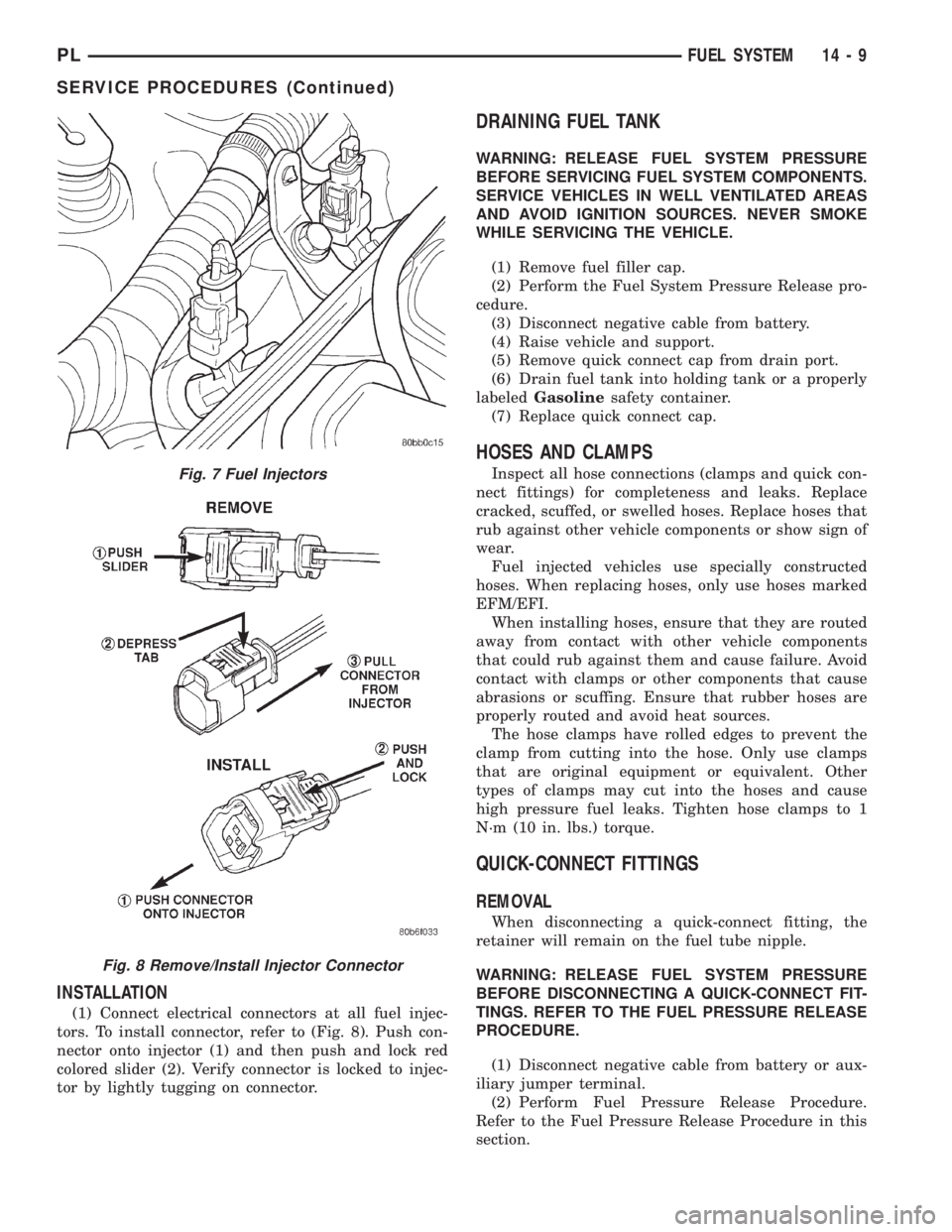
(1) Disconnect electrical connectors at the fuel
injectors. To remove connector refer to (Fig. 8). Pull
the red colored slider away from injector (1). While
pulling the slider, depress tab (2) and remove connec-
tor (3) from injector. The factory fuel injection wiring
harness is numerically tagged (INJ 1, INJ 2, etc.) for
injector position identification. If harness is not
tagged, make note of wiring location before removal.
Fig. 6 Plastic Quick-Connect Fittings
1 ± CASING
2 ± WINDOW
3 ± RETAINER TAB
4 ± NIPPLE
5 ± O RINGS
6 ± WINDOW
7 ± RETAINER ªEARº
14 - 8 FUEL SYSTEMPL
DESCRIPTION AND OPERATION (Continued)
Page 830 of 1285
INSTALLATION
(1) Connect electrical connectors at all fuel injec-
tors. To install connector, refer to (Fig. 8). Push con-
nector onto injector (1) and then push and lock red
colored slider (2). Verify connector is locked to injec-
tor by lightly tugging on connector.
DRAINING FUEL TANK
WARNING: RELEASE FUEL SYSTEM PRESSURE
BEFORE SERVICING FUEL SYSTEM COMPONENTS.
SERVICE VEHICLES IN WELL VENTILATED AREAS
AND AVOID IGNITION SOURCES. NEVER SMOKE
WHILE SERVICING THE VEHICLE.
(1) Remove fuel filler cap.
(2) Perform the Fuel System Pressure Release pro-
cedure.
(3) Disconnect negative cable from battery.
(4) Raise vehicle and support.
(5) Remove quick connect cap from drain port.
(6) Drain fuel tank into holding tank or a properly
labeledGasolinesafety container.
(7) Replace quick connect cap.
HOSES AND CLAMPS
Inspect all hose connections (clamps and quick con-
nect fittings) for completeness and leaks. Replace
cracked, scuffed, or swelled hoses. Replace hoses that
rub against other vehicle components or show sign of
wear.
Fuel injected vehicles use specially constructed
hoses. When replacing hoses, only use hoses marked
EFM/EFI.
When installing hoses, ensure that they are routed
away from contact with other vehicle components
that could rub against them and cause failure. Avoid
contact with clamps or other components that cause
abrasions or scuffing. Ensure that rubber hoses are
properly routed and avoid heat sources.
The hose clamps have rolled edges to prevent the
clamp from cutting into the hose. Only use clamps
that are original equipment or equivalent. Other
types of clamps may cut into the hoses and cause
high pressure fuel leaks. Tighten hose clamps to 1
N´m (10 in. lbs.) torque.
QUICK-CONNECT FITTINGS
REMOVAL
When disconnecting a quick-connect fitting, the
retainer will remain on the fuel tube nipple.
WARNING: RELEASE FUEL SYSTEM PRESSURE
BEFORE DISCONNECTING A QUICK-CONNECT FIT-
TINGS. REFER TO THE FUEL PRESSURE RELEASE
PROCEDURE.
(1) Disconnect negative cable from battery or aux-
iliary jumper terminal.
(2) Perform Fuel Pressure Release Procedure.
Refer to the Fuel Pressure Release Procedure in this
section.
Fig. 7 Fuel Injectors
Fig. 8 Remove/Install Injector Connector
PLFUEL SYSTEM 14 - 9
SERVICE PROCEDURES (Continued)