Page 3535 of 4592

W03543
1MZ±FE Engine :
Engine Wire Clamp
Fulcrum
Length
SST
W04221
5S±FE Engine :
1MZ±FE Engine :Fulcrum
Length
SST Pressure
Feed Tube
Fulcrum
LengthSST
± STEERINGPOWER STEERING VANE PUMP
SR±29
2124 Author�: Date�:
(c) 1MZ±FE Engine:
Using SST, torque the A bolt.
SST 09249±63010
Torque: 29 N´m (293 kgf´cm, 21 ft´lbf)
HINT:
�Use a torque wrench with a fulcrum length of 300 mm
(11.81 in.).
�Disconnect the clamp with engine wire.
(d) Torque the B bolt.
5S±FE and 1MZ±FE Engines:
Torque: 43 N´m (440 kgf´cm, 32 ft´lbf)
(e) Connect the connector to the oil pressure switch.
NOTICE:
Be careful for oil on the connector.
4. CONNECT PRESSURE FEED TUBE
(a) Using SST, connect the tube.
SST 09631±22020
5S±FE Engine:
Torque: 32 N´m (326 kgf´cm, 24 ft´lbf)
1MZ±FE Engine:
Torque: 20 N´m (203 kgf´cm, 15 ft´lbf)
HINT:
�Use a torque wrench with a fulcrum length of 300 mm
(11.81 in.).
�This torque value is effective in case that SST is parallel
to a torque wrench.
(b) 5S±FE Engine:
Install the clamp to the tube.
(c) 5S±FE Engine:
Install the 2 clamp plates and 2 holders to the tube.
(d) 5S±FE Engine:
Install the clamp plate set bolt.
(e) 5S±FE Engine:
Install the clamp plate set nut.
Torque: 10 N´m (100 kgf´cm, 7 ft´lbf)
(f) 1MZ±FE Engine:
Install the 2 clamp plates and 2 holders to the tube.
(g) 1MZ±FE Engine:
Tighten the bolt.
(h) 1MZ±FE Engine:
Install the 2 clamp plate set nuts.
Torque: 7.8 N´m (80 kgf´cm, 69 in.´lbf)
5. CONNECT RETURN HOSE
Page 3553 of 4592

W03102
SST SST Rack Guide
Spring Cap
Lock NutFulcrum
Length
R11667
Claw
R15545
Fulcrum Length
SST
R11668
Brass Bar
± STEERINGPOWER STEERING GEAR
SR±47
2142 Author�: Date�:
16. INSTALL RACK GUIDE SPRING CAP LOCK NUT
(a) Apply sealant to 2 or 3 threads of the nut.
Sealant:
Part No.08833±00080, THREE BOND 1344,
LOCTITE 242 or equivalent
(b) Using SST to hold the rack guide spring cap, and using
SST, torque the nut.
SST 09631±10021, 09922±10010
Torque: 50 N´m (513 kgf´cm, 37 ft´lbf)
NOTICE:
Use SST 09922±10010 in the direction shown in the illustra-
tion.
HINT:
Use a torque wrench with a fulcrum length of 345 mm (13.58
in.).
(c) Recheck the total preload.
Preload (turning):
0.8 ± 1.4 N´m (8 ± 14 kgf´cm, 6.9 ± 12.2 in.´lbf)
(d) Remove the RH and LH rack ends.
17. INSTALL RH AND LH CLAW WASHERS AND RACK
ENDS
(a) Install a new claw washer, and temporarily install the rack
end.
HINT:
Align the claws of the washer with the steering rack grooves.
(b) Using a spanner (24 mm) to hold the steering rack steady,
and using SST, torque the rack end.
SST 09922±10010
Torque: 60 N´m (615 kgf´cm, 45 ft´lbf)
NOTICE:
Use SST 09922±10010 in the direction shown in the illustra-
tion.
HINT:
Use a torque wrench with a fulcrum length of 345 mm (13.58
in.).
(c) Using a brass bar and hammer, stake the washer.
NOTICE:
Avoid any impact to the rack.
Page 3554 of 4592

or less
SST
W04231
Fulcrum
LengthSST SR±48
± STEERINGPOWER STEERING GEAR
2143 Author�: Date�:
18. INSTALL RH AND LH RACK BOOTS, CLAMPS AND
CLIPS
(a) Ensure that the ste")
R11669
W04223
2 mm
(0.79 in.)
or less
SST
W04231
Fulcrum
LengthSST SR±48
± STEERINGPOWER STEERING GEAR
2143 Author�: Date�:
18. INSTALL RH AND LH RACK BOOTS, CLAMPS AND
CLIPS
(a) Ensure that the steering rack hole is not clogged with
grease.
HINT:
If the hole is clogged, the pressure inside the boot will change
after it is assembled and the steering wheel is turned.
(b) Install the boot.
NOTICE:
Be careful not to damage or twist the boot.
(c) Using SST, tighten the clamp as shown in the illustration.
SST 09521±24010
19. INSTALL RH AND LH TIE ROD ENDS AND LOCK NUTS
(a) Screw the lock nut and tie rod end onto the rack end until
the matchmarks are aligned.
(b) After adjusting toe±in, torque the nut.
(See page SA±4)
Torque: 74 N´m (750 kgf´cm, 54 ft´lbf)
20. INSTALL 2 TURN PRESSURE TUBES
(a) Coat 2 new O±rings with power steering fluid and install
them to the tube.
(b) Using SST, install the tube.
SST 09633±00020
Torque: 10 N´m (102 kgf´cm, 7 ft´lbf)
HINT:
�Use a torque wrench with a fulcrum length of 250 mm
(9.84 in.).
�This torque value is effective in case that SST is parallel
to a torque wrench.
Page 3555 of 4592
 Install the gear assembly from the LH of the vehicle.
NOTICE")
SR06Y±01
W04224
SST
Fulcrum
Length
± STEERINGPOWER STEERING GEAR
SR±49
2144 Author�: Date�:
INSTALLATION
1. INSTALL PS GEAR ASSEMBLY
(a) Install the gear assembly from the LH of the vehicle.
NOTICE:
Do not damage the turn pressure tubes.
(b) Torque the 2 gear assembly set bolts and nuts.
Torque: 181 N´m (1,850 kgf´cm, 134 ft´lbf)
HINT:
Lift up the stabilizer bar and install the bolts.
2. INSTALL NO.1 FUEL TUBE PROTECTOR
Install the 2 bolts and nut.
3. CONNECT STABILIZER BAR
Torque the 4 bolts.
Torque: 19 N´m (195 kgf´cm, 14 ft´lbf)
4. CONNECT PRESSURE FEED AND RETURN TUBES
Using SST, connect the tube.
SST 09631±22020
Torque: 32 N´m (326 kgf´cm, 24 ft´lbf)
HINT:
�Use a torque wrench with a fulcrum length of 300 mm
(11.81 in.).
�This torque value is effective in case that SST is parallel
to a torque wrench.
5. CONNECT CLAMP PLATE
Torque the nut.
Torque: 10 N´m (100 kgf´cm, 7 ft´lbf)
6. CONNECT INTERMEDIATE SHAFT ASSEMBLY
(See page SR±16)
7. CONNECT RH AND LH TIE ROD ENDS
(See page SA±10)
8. POSITION FRONT WHEELS FACING STRAIGHT
AHEAD
HINT:
Do it with the front of the vehicle jacked up.
9. CENTER SPIRAL CABLE
(See page SR±16)
10. INSTALL STEERING WHEEL
(a) Install the wheel at straight±ahead position.
(b) Temporarily tighten the wheel set nut.
(c) Connect the connector.
11. BLEED POWER STEERING SYSTEM
(See page SR±4)
12. CHECK STEERING WHEEL CENTER POINT
Page 3562 of 4592
W03088
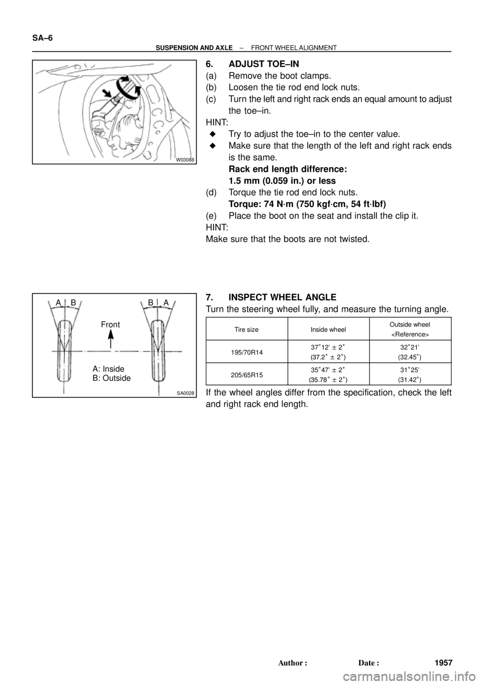
SA0028
A: Inside
B: Outside AB
Front BA SA±6
± SUSPENSION AND AXLEFRONT WHEEL ALIGNMENT
1957 Author�: Date�:
6. ADJUST TOE±IN
(a) Remove the boot clamps.
(b) Loosen the tie rod end lock nuts.
(c) Turn the left and right rack ends an equal amount to adjust
the toe±in.
HINT:
�Try to adjust the toe±in to the center value.
�Make sure that the length of the left and right rack ends
is the same.
Rack end length difference:
1.5 mm (0.059 in.) or less
(d) Torque the tie rod end lock nuts.
Torque: 74 N´m (750 kgf´cm, 54 ft´lbf)
(e) Place the boot on the seat and install the clip it.
HINT:
Make sure that the boots are not twisted.
7. INSPECT WHEEL ANGLE
Turn the steering wheel fully, and measure the turning angle.
Tire sizeInside wheelOutside wheel
195/70R1437°12' ± 2°
(37.2° ± 2°)32°21'
(32.45°)
205/65R1535°47' ± 2°
(35.78° ± 2°)31°25'
(31.42°)
If the wheel angles differ from the specification, check the left
and right rack end length.
Page 3563 of 4592

SA07A±01
SA3213
AB
C D
Front
W03090
± SUSPENSION AND AXLEREAR WHEEL ALIGNMENT
SA±7
1958 Author�: Date�:
REAR WHEEL ALIGNMENT
INSPECTION
1. MEASURE VEHICLE HEIGHT
Vehicle height: See page SA±4
NOTICE:
Before inspecting the wheel alignment, adjust the vehicle
height to specification.
2. INSTALL CAMBER ± CASTER ± KINGPIN GAUGE
ONTO VEHICLE OR POSITION VEHICLE ON WHEEL
ALIGNMENT TESTER
Follow the specific instructions on the equipment manufacturer.
3. INSPECT CAMBER
5S±FE1MZ±FE
Camber
Left±right error±0°42' ± 45'
(±0.7° ± 0.75°)
45' (0.75°) or less±0°45' ± 45'
(±0.75° ± 0.75°)
45' (0.75°) or less
HINT:
Camber in not adjustable, it measurement is not within the
specifications, inspect the suspension parts for damaged and/
or worn±out parts and replace them as necessary.
4. INSPECT TOE±IN
Toe±in
(Total)A + B: 0°24' ± 12' (0.4° ± 0.2°)
C ± D: 4 ± 2 mm (0.16 ± 0.08 in.)
If the toe±in is not within the specification, adjust it at the No.2
lower suspension arm.
5. ADJUST TOE±IN
(a) Measure the length of the left and right No.2 lower sus-
pension arms.
No.2 lower suspension arm length difference:
1 mm (0.04 in.) or less
If the left±right difference is larger than the specification, adjust
the length.
Page 3578 of 4592

1973 Author�: Date�:
4. TEMPORARILY INSTALL OUTBOARD AND INBOARD
JOINT BOOTS AND")
F01747
Inboard Joint BootOutboard Joint Boot
Vinyl tape
R00764
SA±22
± SUSPENSION AND AXLEFRONT DRIVE SHAFT (5S±FE)
1973 Author�: Date�:
4. TEMPORARILY INSTALL OUTBOARD AND INBOARD
JOINT BOOTS AND NEW BOOT CLAMPS
HINT:
�Before installing the boots, wrap the spline of the drive
shaft in vinyl tape to prevent the boots from being dam-
aged.
�Before installing the boots, place 3 new clamps to the
small boot ends and large end (wheel side) and then
install boots to drive shaft.
5. INSTALL TRIPOD
(a) Using a snap ring expander, install a new snap ring.
(b) Place the beveled side of the tripod axial spline toward the
outboard joint shaft.
(c) Align the matchmarks placed before removal.
(d) Using a brass bar and hammer, tap in the tripod to the out-
board joint shaft.
NOTICE:
Do not tap the roller.
(e) Using a snap ring expander, install a new snap ring.
6. INSTALL BOOT TO OUTBOARD JOINT SHAFT
Before assembling the boot, coat the outboard joint and boot
with grease in the boot kit.
Grease capacity: (Color = Black)
100 ± 120 g (3.5 ± 4.2 oz.)
7. INSTALL INBOARD JOINT SHAFT TO OUTBOARD
JOINT SHAFT
(a) Coat the inboard joint and boot with grease in the boot kit.
Grease capacity: (Color = Yellow ocher)
125 ± 155 g (4.4 ± 5.5 oz)
(b) Align the matchmarks placed before removal, and install
the inboard joint shaft to the outboard joint shaft.
(c) Install the boot to the inboard joint shaft.
8. ASSEMBLE BOOT CLAMPS TO BOTH BOOTS
(a) Make sure that the 2 boots are on the shaft groove.
(b) Make sure that the 2 boots are not stretched or contracted
when the drive shaft is at standard length.
Drive shaft standard length
LH609.2 ± 2.0 mm (23.984 ± 0.079 in.)
RH867.3 ± 2.0 mm (34.146 ± 0.079 in.)
Page 3586 of 4592

1981 Author�: Date�:
4. TEMPORARILY INSTALL OUTBOARD AND INBOARD
JOINT BO")
W03195
Inboard Joint BootOutboard Joint Boot
Vinyl Tape
W03196
R14973
SA±30
± SUSPENSION AND AXLEFRONT DRIVE SHAFT (1MZ±FE)
1981 Author�: Date�:
4. TEMPORARILY INSTALL OUTBOARD AND INBOARD
JOINT BOOTS AND NEW BOOT CLAMPS
HINT:
�Before installing the boots, wrap the spline of the drive
shaft in vinyl tape to prevent the boots from being dam-
aged.
�Before installing the boots, place 3 new clamps to the
small boot ends and large end (wheel side) and then
install boots to drive shaft.
5. INSTALL INBOARD JOINT SHAFT TO OUTBOARD
JOINT SHAFT
Align the matchmarks placed at removal, and using a snap ring
expander, put in the inboard joint shaft expanding the snap ring.
6. INSTALL BOOT TO OUTBOARD JOINT
Before assembling the boot, pack the outboard joint and boot
with grease in the boot kit.
Grease capacity: (Color = Black)
105 ± 125 g (3.7 ± 4.4 oz.)
7. INSTALL BOOT TO INBOARD JOINT SHAFT
(a) Pack the inboard joint and boot with grease in the boot kit.
Grease capacity: (Color = Gray)
Joint side: 142.5 ± 157.5 g (5.0 ± 5.6 oz.)
Boot side: 52.5 ± 57.5 g (2.1 ± 2.3 oz.)
(b) Install the boot to the inboard joint shaft.
8. ASSEMBLE BOOT CLAMPS TO BOTH BOOTS
(a) Make sure that the 2 boots are on the shaft groove.
(b) Make sure that the 2 boots are not stretched or contracted
when the drive shaft is at standard length.
Drive shaft standard length:
M/T LH601.5 ± 2.0 mm (23.681 ± 0.079 in.)
RH871.6 ± 2.0 mm (34.315 ± 0.079 in.)
A/T LH586.0 ± 2.0 mm (23.071 ± 0.079 in.)
RH881.6 ± 2.0 mm (34.709 ± 0.079 in.)
(c) Holding the clamp near the closing hooks, using pliers,
position the holes in the clamp's free end over the closing
hooks.
(d) Secure clamp by drawing the closing hooks together.