Page 3391 of 4592
SFI SYSTEM
SF±3
1502 Author�: Date�:
(b) When connecting the union bolt on th")
S05054
New Gasket
FI1654
Fulcrum Length
30 cm
SST
FI6372 FI6372
New O±Ring
Grommet
InjectorCORRECT
WRONG
± SFI (1MZ±FE)SFI SYSTEM
SF±3
1502 Author�: Date�:
(b) When connecting the union bolt on the high pressure pipe
union, observe these procedures:
(1) Always use 2 new gaskets.
(2) Tighten the union bolt by hand.
(3) Tighten the union bolt to the specified torque.
Torque: 32.5 N´m (330 kgf´cm, 24 ft´lbf)
(c) When connecting the flare nut on the high pressure pipe
union, observe these procedures:
(1) Apply a light coat of engine oil to the flare nut, and
tighten the flare nut by hand.
(2) Using SST, tighten the flare nut to specified torque.
SST 09631±22020
NOTICE:
Do not rotate the fuel pipe, when tightening the flare nut.
Torque: 28 N´m (285 kgf´cm, 21 ft´lbf) for using SST
HINT:
Use a torque wrench with a fulcrum length of 30 cm (11.81 in.).
(d) Observe these precautions when removing and installing
the injectors.
(1) Never reuse the O±ring.
(2) When placing a new O±ring on the injector, take
care not to damage it in any way.
(3) Coat a new O±ring with spindle oil or gasoline be-
fore installing±never use engine, gear or brake oil.
Page 3420 of 4592
SF07O±03
BO0919
Crack Leakage
Deformation
Z10162
SSTUse SST
28 N´m
(285 kgf´cm, 21 ft´lbf)
Fulcrum
Length
30 cm
(11.81 in.)
SST: 09631±22020
FU0041
PipeHose
Clip 2 ± 7 mm (0.08 ± 0.28 in.)
0 ± 3 mm (0 ± 0.12 in.)
SF±32
± SFI (1MZ±FE)FUEL TANK AND LINE
1531 Author�: Date�:
INSPECTION
INSPECT FUEL TANK AND LINE
(a) Check the fuel lines for cracks or leakage, and all connec-
tions for deformation.
(b) Check the fuel tank vapor vent system hoses and connec-
tions for looseness, sharp bends or damage.
(c) Check the fuel tank for deformation, cracks, fuel leakage
or tank band looseness.
(d) Check the filler neck for damage or fuel leakage.
(e) Hose and pipe connections are as shown in the illustra-
tion.
If a problem is found, repair or replace the parts as necessary.
Page 3475 of 4592
STARTER
ST±9
1716 Author�: Date�:
3. INSPECT FIELD COIL
(a)")
P10588
Ohmmeter
Continuity
P10589
Ohmmeter
No Continuity
Z10079
Brush Holder Side
Field Flame SideLength
Length
ST0019
± STARTING (5S±FE)STARTER
ST±9
1716 Author�: Date�:
3. INSPECT FIELD COIL
(a) Check the field coil for open circuit.
Using an ohmmeter, check that there is continuity be-
tween the lead wire and field coil brush lead.
If there is no continuity, replace the field frame.
(b) Check the field coil for ground.
Using an ohmmeter, check that there is no continuity be-
tween the field coil end and field frame.
If there is continuity, repair or replace the field frame.
4. INSPECT BRUSHES
Using vernier calipers, measure the brush length.
Standard length: 15.5 mm (0.610 in.)
Minimum length: 10.0 mm (0.394 in.)
If the length is less than minimum, replace the brush holder and
field frame.
5. INSPECT BRUSH SPRINGS
Check the brush spring load.
Take the pull scale reading the instant the brush spring
separates from the brush.
Standard spring installed load:
1.2 kW13.7 ± 19.6 N (1.4 ± 2.0 kgf, 3.0 ± 4.4 lbf)
1.4 kW17.6 ± 23.5 N (1.8 ± 2.4 kgf, 3.9 ± 5.3 lbf)
Minimum spring installed load:
1.2 kW9.8 N (1.0 kgf, 2.2 lbf)
1.4 kW11.8 N (1.2 kgf, 2.6 lbf)
If the installed load is less than minimum, replace the brush
springs.
Page 3495 of 4592
STARTER
ST±9
1736 Author�: Date�:
3. INSPECT FIELD COIL
(a)")
P10588
Ohmmeter
Continuity
P10589
Ohmmeter
No Continuity
Z10079
Brush Holder Side
Field Flame SideLength
Length
ST0019
± STARTING (1MZ±FE)STARTER
ST±9
1736 Author�: Date�:
3. INSPECT FIELD COIL
(a) Check the field coil for open circuit.
Using an ohmmeter, check that there is continuity be-
tween the lead wire and field coil brush lead.
If there is no continuity, replace the field frame.
(b) Check the field coil for ground.
Using an ohmmeter, check that there is no continuity be-
tween the field coil end and field frame.
If there is continuity, repair or replace the field frame.
4. INSPECT BRUSHES
Using vernier calipers, measure the brush length.
Standard length: 15.5 mm (0.610 in.)
Minimum length: 10.0 mm (0.394 in.)
If the length is less than minimum, replace the brush holder and
field frame.
5. INSPECT BRUSH SPRINGS
Check the brush spring load.
Take the pull scale reading the instant the brush spring
separates from the brush.
Standard spring installed load:
1.2 kW13.7 ± 19.6 N (1.4 ± 2.0 kgf, 3.0 ± 4.4 lbf)
1.4 kW17.6 ± 23.5 N (1.8 ± 2.4 kgf, 3.9 ± 5.3 lbf)
Minimum spring installed load:
1.2 kW9.8 N (1.0 kgf, 2.2 lbf)
1.4 kW11.8 N (1.2 kgf, 2.6 lbf)
If the installed load is less than minimum, replace the brush
springs.
Page 3529 of 4592

SR06Q±01
R15196
Caliper Gauge
Micrometer
Vane Pump Shaft
Bushing
Front Housing
N00372
Thickness
Height
Length
R10282
Feeler Gauge
± STEERINGPOWER STEERING VANE PUMP
SR±23
2118 Author�: Date�:
INSPECTION
NOTICE:
When using a vise, do not overtighten it.
1. CHECK OIL CLEARANCE BETWEEN VANE PUMP
SHAFT AND BUSHING
Using a micrometer and caliper gauge, measure the oil clear-
ance.
5S±FE and 1MZ±FE Engines:
Standard clearance:
0.03 ± 0.05 mm (0.0012 ± 0.0020 in.)
Maximum clearance: 0.07 mm (0.0028 in.)
If it is more than the maximum, replace the front housing and
vane pump shaft.
2. INSPECT VANE PUMP ROTOR AND VANE PLATES
(a) Using a micrometer, measure the height, thickness and
length of the plates.
5S±FE and 1MZ±FE Engines:
Minimum height: 8.6 mm (0.339 in.)
Minimum thickness: 1.397 mm (0.0550 in.)
Minimum length: 14.991 mm (0.5902 In.)
(b) Using a feeler gauge, measure the clearance between
the rotor groove and plate.
5S±FE and 1MZ±FE Engines:
Maximum clearance: 0.035 mm (0.0014 in.)
If it is more than the maximum, replace the plate and/or rotor
with one having the same mark stamped on the cam ring.
Page 3530 of 4592

R13897
Inscribed Mark
R11288
R07591
Compressed Air
R11563Inscribed Mark SR±24
± STEERINGPOWER STEERING VANE PUMP
2119 Author�: Date�:
5S±FE and 1MZ±FE Engines:
Inscribed mark: 1, 2, 3, 4 or None
HINT:
There are 5 vane lengths with the following rotor and cam ring
marks:
5S±FE and 1MZ±FE Engines:
Rotor and cam
ring markVane plate part
numberVane plate length
mm (in.)
None44345±2601014.999±15.001
(0.59051±0.59059)
144345±2602014.997±14.999
(0.59043±0.59051)
244345±2603014.995±14.997
(0.59035±0.59043)
344345±2604014.993±14.995
(0.59027±0.59035)
444345±2605014.991±14.993
(0.59020±0.59027)
3. INSPECT FLOW CONTROL VALVE
(a) Coat the valve with power steering fluid and check that it
falls smoothly into the valve hole by its own weight.
(b) Check the valve for leakage. Close one of the holes and
apply 392±490 kPa (4±5 kgf/cm
2, 57±71 psi) of com-
pressed air into the opposite side, and confirm that air
does not come out from the end holes.
If necessary, replace the valve with one having the same letter
as inscribed on the front housing.
5S±FE and 1MZ±FE Engines:
Inscribed mark: A, B, C, D, E or F
Page 3531 of 4592
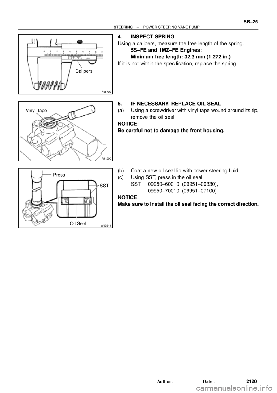
R08702
Calipers
R11290
Vinyl Tape
W03541
Press
SST
Oil Seal
± STEERINGPOWER STEERING VANE PUMP
SR±25
2120 Author�: Date�:
4. INSPECT SPRING
Using a calipers, measure the free length of the spring.
5S±FE and 1MZ±FE Engines:
Minimum free length: 32.3 mm (1.272 in.)
If it is not within the specification, replace the spring.
5. IF NECESSARY, REPLACE OIL SEAL
(a) Using a screwdriver with vinyl tape wound around its tip,
remove the oil seal.
NOTICE:
Be careful not to damage the front housing.
(b) Coat a new oil seal lip with power steering fluid.
(c) Using SST, press in the oil seal.
SST 09950±60010 (09951±00330),
09950±70010 (09951±07100)
NOTICE:
Make sure to install the oil seal facing the correct direction.
Page 3534 of 4592
SR06S±01
W03361
5S±FE Engine :
1MZ±FE Engine :Pressure Feed Tube
Stopper
Pressure
Feed
StopperTube
W03360
Example 5S±FE Engine :
A
B
W03542
5S±FE Engine :
SST
Fulcrum
Length SR±28
± STEERINGPOWER STEERING VANE PUMP
2123 Author�: Date�:
INSTALLATION
1. INSTALL PRESSURE FEED TUBE
(a) Torque the union bolt with a new gasket.
HINT:
Make sure the stopper of the tube is touching the front bracket,
as shown, then torque the union bolt.
5S±FE and 1MZ±FE Engines:
Torque: 52 N´m (525 kgf´cm, 38 ft´lbf)
(b) Install the oil pressure switch to the union bolt.
5S±FE and 1MZ±FE Engines:
Torque: 21 N´m (210 kgf´cm, 15 ft´lbf)
2. INSTALL PS VANE PUMP ASSEMBLY WITH PRESS-
ER FEED TUBE
Temporarily tighten the 2 (A and B) bolts.
3. INSTALL DRIVE BELT
(a) Adjust drive belt tension.
(See page SR±3)
(b) 5S±FE Engine:
Using SST, torque the A bolt.
SST 09249±63010
Torque: 29 N´m (293 kgf´cm, 21 ft´lbf)
HINT:
Use a torque wrench with a fulcrum length of 300 mm (11.81
in.).

Fulcrum
Length
30 cm
(11.81 in.)
SST: 09631±22020
FU0041
PipeHose
Clip 2 ± 7 mm (0.08 ± 0.28 in.)
0 ±")